
Hey, I am a 5th year Mechatronic Engineering student at the University of Glasgow, and this is my online portfolio.You can contact me at my emails - [email protected], and [email protected] for your time!
Don't wanna be here? Send us removal request.
Statistics
We looked inside some of the posts by gautamgupta-blog1 and here's what we found interesting.
Average Info
Notes Per Post
1
Likes Per Post
1
Reblog Per Post
0
Reply Per Post
0
Time Between Posts
2 months
Number of Posts By Type
Photo
8
Video
2
Last Seen Tumblr Blogs


Fun Fact
Tumblr has a 66 index score for customer satisfaction in the US.
Photo

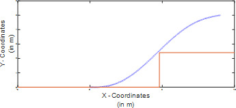
Although a bit low-res (my bad! these are from my report!), these images show what I have been working on recently. The bottom picture shows a smooth trajectory my program generates for an autonomous vehicle to park! The red line shows one of the boundaries of the parking space (the other boundary is at zero, so I did not plot that one), while the blue line shows the actual path the car would follow to go into the parking space in one motion. This path is made of a fifth order polynomial, which can be solved with simple algebra to generate an uber-smooth trajectory!
The other picture shows the velocity that the vehicle will follow on this path, and therefore reduce the effort of the controller.
0 notes
Video
tumblr
In this video, you can see a QR Code reader I made as part of my Team Design Project last year. Even though the results are appearing on my gigantic laptop, don’t be fooled! This program is running full 1080p HD video using the tiny Raspberry Pi you might be able to make out next to my laptop! This code was made as part of a Museum Guide Robot, who uses QR codes to confirm it’s position on the museum floor.
This program reads the QR code using ZBar, and then converts that QR code into lateral and longitudinal distance from the camera, and the facing angle as well, which are flashing on the laptop screen. The laptop is connected to the Pi using VNC Viewer, which enables me to debug the Pi wirelessly.
In addition to these, I also made a sound file player and a text file reader for the robot as well, but they are not as glamorous as this.
0 notes
Photo

This is the schematic of the sunsensor array I am currently designing for the UKSEDS Satellite Design Competition, and it is based on an Arduino Uno R3 microcontroller.
This design is cool because I am using 8-to-1 multiplexers to connect about 20 OPT101 sunsensors to the microcontroller, with a sensor on each corner of each face of the CubeSat. 3 sun sensors on every corner will be triggered by the same code sent to the control pins of the multiplexers.
0 notes
Photo


This is the cargo bike I created as part of my Mechanical Design Project in my 2nd year. I personally designed the disk brakes (both the disc and the calipers), and the front fork. I also helped on the frame and the cargo box.
This bike is designed to be sold en mass to delivery companies, who might be looking to switch to a greener mode of transportation for their delivery drivers. Therefore, disc brakes were provided to ensure complete control of the bike by the rider despite heavy loads creating greater inertia. The discs were designed to ensure good grip even in rainy conditions, and were designed to be made custom by us instead of buying from an external manufacturer in order to reduce prices. We were required to think about all aspects of the project, from researching the market viability for our bike to a rough estimate of costs. We also used techniques like House of Quality in order to determine the viability of different design considerations. We also had to track our progress using a Gantt chart, and comment upon our initial estimations for the project versus how much time it actually took in the end. Fun shit indeed!
0 notes
Photo


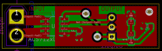
This is the LDR Array system I created based on an Arduino Nano for the UKSEDS Satellite Design Competition Entry by GU Orbit, and hey, we are in the finals right now!
This system runs on comparing the voltage drops across the LDRs with the voltage drops at absolute dark and absolute saturation light to determine where bright spots are in the room, so that the camera doesn’t need to do complete 360 degree rotations everytime. I will upload my soldered version of this PCB later!
0 notes
Photo

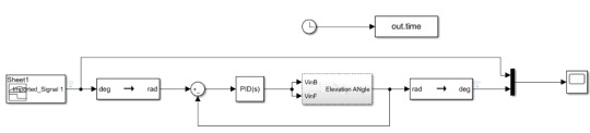

This is a control system I designed as a part of my Mechatronics Team Design Project 3 this past academic year. It is meant for a UAV rig having three degrees of freedom, with us controlling two (and by extension the third).
The first image shows the entirety of the mathematical model of the system made in Simulink by me. All the boxes contain different subsystems representing the different degrees of freedom in the model (namely, Elevation, Pitch, and Azimuth).
The other two pictures are the PID control systems we designed for this model jointly. The first one depicts the azimuthal controller, and the second one is the elevation controller. Tuning controllers is such a pain!
0 notes
Photo

This is a fancy render of the CubeSat body I designed using SolidWorks for GU Orbit’s entry into the UKSEDS Satellite Design Competition 2019-2020. We are in the finals this year, and hopefully will win it!
This design contains a mock up for where each subsystem is going to go, with some empty space for payload, some empty space for power storage, and some mock up circuit-boards. I wanted to make them according to PC-104 specifications but alas a CubeSat is too small for standardization sometimes. It also has deployable solar panels (shown in their deployed state right now) which will operate on a burn wire mechanism.
0 notes
Photo

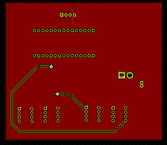
This the PCB I designed for the sun sensors and magnetorquer prototyping system for the Control Team in GU Orbit. The sun sensors (OPT101s, for anyone interested) will be used to locate the position of the sun relative to the satellite, in order to gauge how to best align the CubeSat to get maximum exposure to sun.
To turn the CubeSat in space, and also to detangle it and put it into the correct orbit after ejection from the spacecraft, we are employing Magnetorquers on our CubeSat, which are basically coils of wire on circuit board, which are present on all three axes (this is a massive simplification but oh well) that we charge up to align the satellite a certain way with respect to Earth’s magnetic field, much like how a compass works.
0 notes
Photo
This is a simple Hall Sensor PCB I designed as a part of the Embedded Systems team of GU Orbit. I designed this using KiCAD, which I am fairly proficient in now. I also soldered it up, but alas forgot to take any pictures, and it currently sits in my flat in Glasgow
0 notes
Video
tumblr
This is a Heartrate Sensor I made in 2nd Year, as part of my Electronic Design Project 2 module. We designed this to be used by sports professionals to treat injuries on the field, where a minimum of equipment is required. It is based on a Freedom KL-25Z micro-controller, and as you can see, it can show both the pulse and the BPM of the person. It also features an LED blinking in time with the person’s heartbeats, in order to give the first-aid responder a quick look at the condition of the injured person, and it also has an adjustable brightness using the touch pad on the KL-25Z.
1 note
·
View note