
Don't wanna be here? Send us removal request.
Statistics
We looked inside some of the posts by georgebeltphysicalcomputing and here's what we found interesting.
Average Info
Notes Per Post
0
Likes Per Post
0
Reblog Per Post
0
Reply Per Post
0
Time Between Posts
8 days
Number of Posts By Type
Text
11
Photo
1
Last Seen Tumblr Blogs


Fun Fact
The “We are the 99%” Tumblr blog became the slogan for the Occupy Wall Street movement.
Text
Anti-Coronavirus Hat (Or the Rootin’ Tootin’ Coronavirus Shootin’ Cowboy Hat): Final Entry
A video of the final product!
Youtube Link
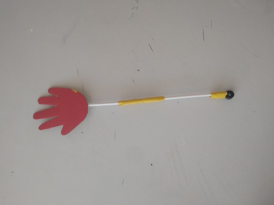
Here I am, at the end of the university year and the deadline of the anti-coronavirus hat which has caused me so much pain and strife. I have made some more adjustments to the code, added the second servo and the slappers which punish those who dare touch their face’s with their rona covered hands. The slappers themselves underwent two itterations, the first being made with 3 cottonbuds which was too long and flimsy. Mk2 was made out of just two cotton buds which slapped the face at a better position and flapped around a lot less.
Mk1:

Mk2:
The changes to the code have been to change the range of detection, in order to bring it in as it was far too wide to begin with, registering movement down to my waist. I have also edited the delays to make it snappier and moved the final delay, which allowed everything to catch up, into the if statement which controls movement of the servos. My thinking is that if its only there for things to catch up, things only need to catch up if they’ve moved. One big issue I hadn’t realised was that if you moved your hand under the hat while it was in its delay, it wouldn’t register and wouldn’t hit you. Now by essentially removing the delay, provided nothing has triggered it in the last loop, it should be a lot snappier at registering hands.
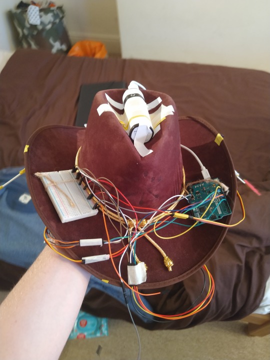
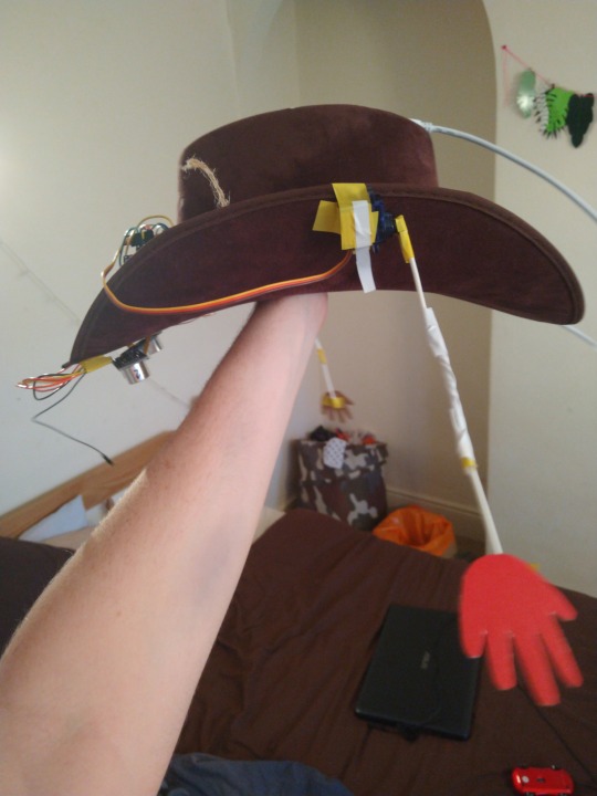
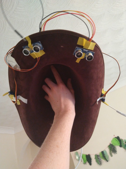
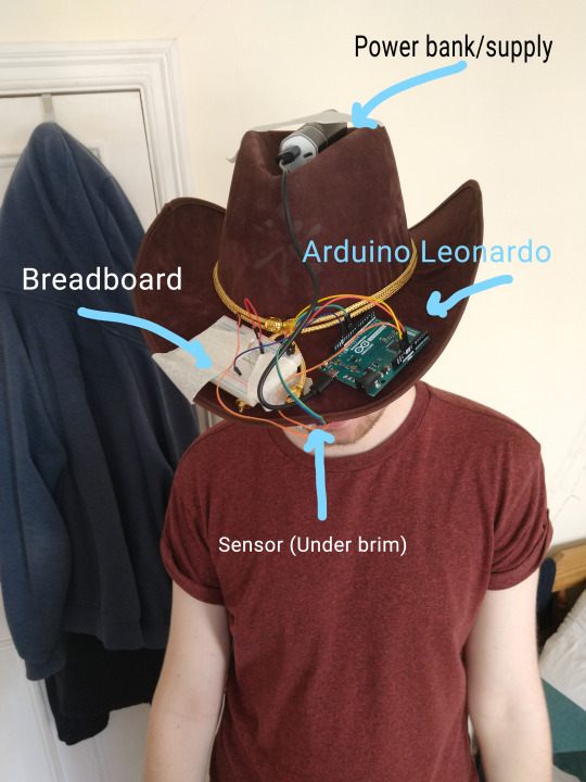
Here are a few photos of the final product. The wires are a bit of a mess, but I think it adds to a kind of cyberpunk aesthetic? Maybe? I dont know, but here it is:
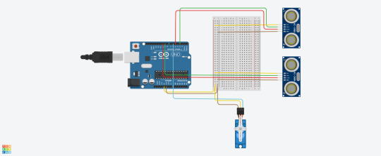
Here is a final circuit diagram:
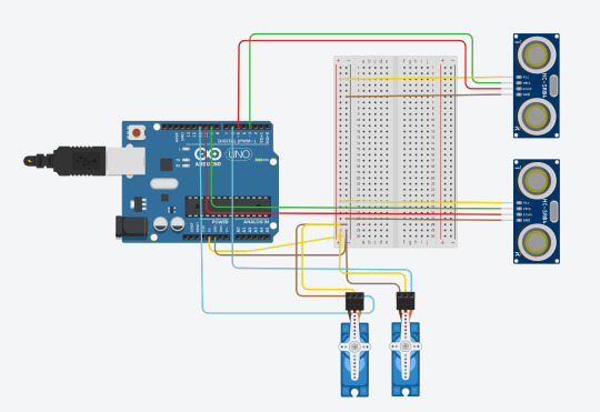
The circuit diagram looks a lot neater than the final product but the circuit is technically the same, I have just had to double up most of the wires so that they can reach across the entire thing. I have also added a ‘killswitch’ of sorts, which cuts off power to the breadboard that I couldn’t represent in the tinkercad diagram. This allows me to put the hat on without being harrased violently by the slappers which became a bit of a problem.
--------------------
Evaluation -
The good: The hat works most of the time. It detects a hand on a face and slaps the user accordingly. I think it looks quite cool, all things considered. It was interesting and fun to make, im really happy with the final product. When I started the project I had literally 0 experience with either Arduino or electronics so I am proud of how far I have come and how much I’ve learned. I would love to continue the project or start a new one, learning more and making cooler stuff.
The bad: It doesn’t work every time. It works most of the time, sure, but not every time. Sometimes it triggers for no reason, sometimes a hand wont trigger it. That is down to me not understanding how the code, or electronics, or parts work. It is also poorly designed in places. The way the sensors are placed means if you scratch your nose dead centre, it wont register. If you want to adjust your glasses, you get slapped. It is also frustratingly simple. The code at the end, is not much more complicated than the first few iterations of it. I gradually made it more complex to try and get it to work, before learning how arduino and electronics work and realising that I need to make it less complex to work.
The future: Of course the current situation allowed my hat to be created, but it also added quite a lot of limitations. Being unable to experiment with parts without having to buy them and send them back if they weren’t suitable, unlike how I would have been able too at uni, did prevent me from trying out some ideas I had for the project like adding some sort of defence against people coming too close to you, like a small spray of water or speaker. Or perhaps making the hat itself more complicated; maybe instead of slapping you it wipes you with antibacterial wipes? Maybe add a button to turn it on or off, as opposed to just pulling the wire which gives the thing power. To improve the hat itself, would require different parts. I think the fact the sensors use more of a ‘line’ than a cone of detection prevents it from working a lot more than it could, although im not sure if any such product exists. A casing or better setup for the hat would also probably make it work better. I was tempted to cut holes in the hat to make room for parts and wires, but was worried that if I needed to change things around more than a few times the hat would break. A specially designed hat, or maybe 3D printed platform would also help a lot with balancing the parts and making it neater.
--------------------
A list of parts used:
Sensors
Wires
Power bank
Servos
A link to the final code in all its glory(Github repo)
Thank you!
0 notes
Text
Anti-Coronavirus Hat: Some progress, some delays
I think the electronics are done, I can’t see anything that needs to change about them which is good, the only addition will be when I eventually add another servo for the other side of the hat.
The code, however, has been changed yet again although I haven’t added a huge amount, mostly just things that write to the console to that I can understand what is going on. I also changed the size of the area the hat detects from 150cm to 100cm to hopefully reduce some of the ‘false positives’ it recieves.
The changes to the code this time were mostly reshuffling as I realised I needed some sort of timer so that if you just brush your hand in front of your face, it wont hit you, and also hopefully reduce some of the ‘false positives’ it recieves from incorrect readings from the sensors. I initially looked into the idea of co-routines, hoping to use something similar to what I am familiar with from work with Unity. I found this arduino package, apparently made for this exact reason. However, the documentation wasn’t massively useful and I struggled to figure out how to use them properly. After about an hour I gave up and looked for alternative solutions using the built in delay function in Arduino.
The code functions, kind of, but I need to do more testing with it actually working with the hat.
The code now works like this (I will post the entirety of the code at the bottom of this post):
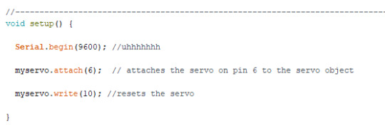
First the set-up. Serial.begin sets something up with the console but im not really sure. It seems important though so I’ve left it in. Next it attaches the servo to pin 6, then tells it to move to position 10, which resets it, for reasons explained in previous posts.
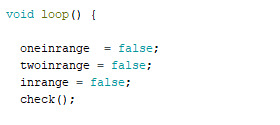
Next, into the loop function. Firstly, it sets these three booleans to false. This tells the hat nothing has been detected infront of the sensors. Then it enters the check function.
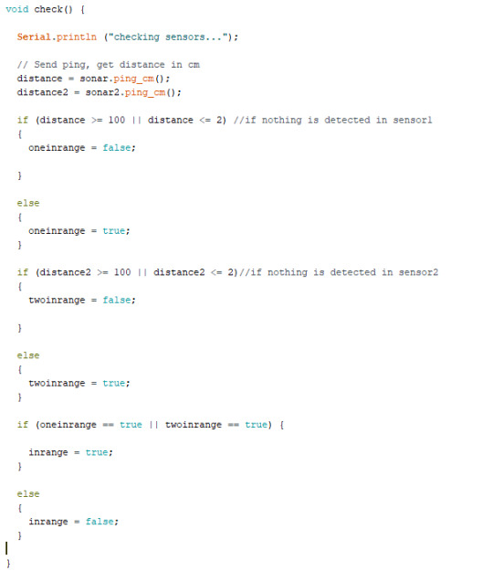
The check function gets the most recent readings from the sensors and puts them into the variables distance and distance2 for senors 1 and 2 respectively. The next two if and else statements check the readings to see if something has been detected within the range I have set (Between 100 and 2 cm) if something has been detected, the boolean representing that sensor is changed to positive. Finally, if either of the values have been changed to positive, the boolean inrange is set to true. This means the code now knows something, somewhere has been detected.
After this, the code exits the check function and enters this if statment. If nothing has been detected and inrange is still false, it skips the if statement, waits 0.2 seconds and starts from the top. If something has been detected and inrange is now true, it holds for a second, then runs the check function again. When that is completed, the values may have changed, or not, but if something has been detected still, in either of the sensors, inrange will still be true. As a result of this, the servo is told to move and it smacks the user. If after the second check, the sensors pick up nothing, the servos don’t move and it resets again.
Here is the code in the entirety, with the console stuff included:
// Include NewPing Library------- #include "NewPing.h" #include <Servo.h>
// Hook up sensor with Trigger to Arduino Pin 9, Echo to Arduino pin 10 #define TRIGGER_PIN 9 #define ECHO_PIN 10
// Hook up sensor2 with Trigger to Arduino Pin 3, Echo to Arduino pin 5 #define TRIGGER_PIN2 3 #define ECHO_PIN2 5
// Maximum distance for ping (in centimeters).-------- #define MAX_DISTANCE 400
// NewPing setup of pins and maximum distance ---------- NewPing sonar(TRIGGER_PIN, ECHO_PIN, MAX_DISTANCE); NewPing sonar2(TRIGGER_PIN2, ECHO_PIN2, MAX_DISTANCE); float duration, distance, distance2;
//SERVO STUFF--------------- Servo myservo; // create servo object to control a servo int pos = 200; //the position the servo will move too when triggered //BOOLEAN STUFF ------------------------------------------------------- bool inrange; bool oneinrange; bool twoinrange;
//----------------------------------------------------------------------------------------------------------- void setup() {
Serial.begin(9600); //uhhhhhhh
myservo.attach(6); // attaches the servo on pin 6 to the servo object
myservo.write(10); //resets the servo
}
//-----------------------------------------------------------------------------------------------------------
void loop() {
oneinrange = false; twoinrange = false; inrange = false; Serial.println("Check number 1"); check(); Serial.println("");
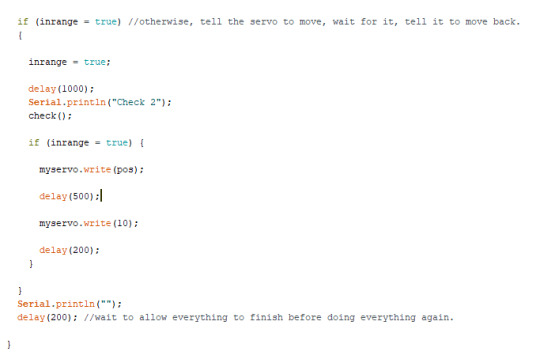
if (inrange = true) //otherwise, tell the servo to move, wait for it, tell it to move back. {
inrange = true;
delay(1000); Serial.println("Check 2"); check();
if (inrange = true) {
myservo.write(pos);
delay(500);
myservo.write(10);
delay(200); }
} Serial.println(""); delay(200); //wait to allow everything to finish before doing everything again.
}
//----------------------------------------------------------------------------------------------------------- void check() {
Serial.println ("checking sensors...");
// Send ping, get distance in cm distance = sonar.ping_cm(); distance2 = sonar2.ping_cm();
if (distance >= 100 || distance <= 2) //if nothing is detected in sensor1 { Serial.println("1 nothing detected"); Serial.print("Distance1 = "); Serial.println(distance); oneinrange = false;
}
else { Serial.println("1 detected"); Serial.print("Distance1 = "); Serial.println(distance); oneinrange = true; }
if (distance2 >= 100 || distance2 <= 2)//if nothing is detected in sensor2 { Serial.println("2 nothing detected"); Serial.print("Distance2 = "); Serial.println(distance2); twoinrange = false;
}
else { Serial.println("2 detected"); Serial.print("Distance2 = "); Serial.println(distance2); twoinrange = true; }
if (oneinrange == true || twoinrange == true) {
inrange = true; }
else { inrange = false; }
Serial.print("In range = "); Serial.println(inrange);
}
0 notes
Text
Anti-Coronavirus Hat: Progress!
Using both the new code for the servo, and fixing some issues with the old stuff, I think the logistics of the hat are working better than before!
First off: The cons. The ultrasonic sensors are dodgy at best, but they are very cheap. I have 4 of them, but I’m currently 2 down as those don’t work more than they work, which is better than the ones I am currently using which work more than they dont work. They do however return a crazy high value sometimes, and quite often return 0 when being moved. But they work well enough.
Now the pros: The code is much much better. I figured out a few issues with the movement of the servos and the delays. In some places the code wasn’t allowing the servo to complete its movements before telling it to move again, which has now been resolved so it worked a lot better. It also returns to a default position of 10 as when it returned to 1 it would sometimes try and move too far back and stutter. Now, as it moves back to 10, if it tries to move back a little further (for reasons I can’t understand) it has plenty of leeway. Also, with the new delays, the servo is able to move much further than before, which I believe will hopefully provide more of a slap than a tap.
Finally, I have decided not to use an average distance from both sensors to detect a hand. I thought it through and couldn’t really think of a reason why this was better than just triggering the servos if one of the sensors is triggered. Having an average just complicated the code and the electronics.
Here is a video of the sensors misbehaving even when they are both on a steady, flatish surface.
Here is a video of the hat working better than it ever has before, although granted not actually on the hat itself yet.
I think the hardest part now will be overcoming the sensor’s limitations. As the ultrasonic ‘beam’ is more of a straight line than a cone, I have to make sure they are positioned just right, so your dirty, ‘rona-ridden, hand always breaks the line when you touch your face. I am considering adding more sensors to help this, but I am running out of space on the arduino, let alone not having working sensors. We will have to see when I put it together again.
Here is the updated code with some comments!
// Include NewPing Library------- #include "NewPing.h" #include <Servo.h>
// Hook up sensor with Trigger to Arduino Pin 9, Echo to Arduino pin 10 #define TRIGGER_PIN 9 #define ECHO_PIN 10
// Hook up sensor2 with Trigger to Arduino Pin 3, Echo to Arduino pin 5 #define TRIGGER_PIN2 3 #define ECHO_PIN2 5
// Maximum distance for ping (in centimeters).-------- #define MAX_DISTANCE 400
// NewPing setup of pins and maximum distance ---------- NewPing sonar(TRIGGER_PIN, ECHO_PIN, MAX_DISTANCE); NewPing sonar2(TRIGGER_PIN2, ECHO_PIN2, MAX_DISTANCE); float duration, distance, distance2;
//SERVO STUFF--------------- Servo myservo; // create servo object to control a servo int pos = 200; //the position the servo will move too when triggered
void setup() {
Serial.begin(9600); //uhhhhhhh
myservo.attach(6); // attaches the servo on pin 6 to the servo object
myservo.write(10); //resets the servo
}
void loop() {
// Send ping, get distance in cm distance = sonar.ping_cm(); distance2 = sonar2.ping_cm();
//Send results to Serial Monitor Serial.print("Distance1 = "); Serial.println(distance); Serial.print("Distance2 = "); Serial.println(distance2);
if (distance >= 150 || distance <= 2) //if nothing is detected in sensor1 { Serial.println("1 out of range"); }
if (distance2 >= 150 || distance2 <= 2)//if nothing is detected in sensor1 { Serial.println("2 out of range"); }
else //otherwise, tell the servo to move, wait for it, tell it to move back. { Serial.println("in range");
myservo.write(pos);
delay(500);
myservo.write(10);
delay(200); }
delay(500); //wait to allow everything to finish before doing everything again.
}
Thank you!
0 notes
Text
Servo Problems
An issue I have struggled with since beginning this project was the servo seeming to have a mind of their own. They would occasionaly move more, or less than I thought I had told them too, they would trigger randomly, but due to how volatile the signals I was getting are, I couldn’t figure out what was going wrong.
I have isolated the servo entirely in the code, commenting out everything but this:
void loop() {
myservo.write(pos);
delay(1000);
myservo.write(-pos);
}
with pos being 80. This code, although simplified and isolated, is essentially what I am using to move my servos in the full project. Here is the video of this code in action
I then upped pos to 200 to see if that made any difference, but it still made small, janky movements making me think my code was the issue, not the amount I was telling the servo to move which was my first thought. As far as I could see, it should move, wait, then move back, but the video clearly shows it moving, then back and then waiting. I watched this video and it became clear. I believe the issue was that I was trying to go back too far perhaps?
Regardless I changed the code to this:
myservo.write(pos);
delay(1000);
myservo.write(0);
delay(1000);
And it works wonderfully! Here you can see DJ servo playing along to some music at the same tempo as its movements
Hopefully, with the code fixed I’ll be able to better implement it into my actual project!
0 notes
Text
Anti-Coronavirus hat: Sticking point
I’m struggling to make much more progress. I’ve eddited the code to go back to the idea of averaging out a value from both sensors. It works better now than before, but it still doesn’t seem to work on the hat much. It does’n’t help that testing is a nightmare because I need to attach and detatch everything each time I want to test it on the hat.
In regards to the power issue, I did some testing and can’t figure out what was going wrong as in my very rudimentary tests the power bank was constantly supplying the arduino with power... I think it might have been a dodgy connection, or a button was being pressed somewhere by accident. Regardless, I have a belly full of stew and Im tired so i’m giving up today. I’ll have another crack tomorrow
0 notes
Text
Anti-Coronavirus Hat: Further Progress
I am more or less happy with the theory behind the circuit so I stuck it all back on the hat with a little more thought and ran the first proper tests. As you can see through the video, I struggled to get the detection to work. The placement of the sensors will need a lot of work to function properly. Also, the hat is so heavily weighted towards the front it needs something heavy at the back to stop it falling off your head.
Other than those large, glaring issues, it did kind of work and I am confident I can get a fully functioning version working soon.
Here is the video:
https://www.youtube.com/watch?v=pw_5IHERMg0
Here is an (unfinished) circuit diagram:
I also removed the LED as it just confused things and wasn’t actually that useful for testing as well as making the code a lot better.
The only issue I see being unsolvable is the power. I think that the powerbank I bought knows its not ‘charging’ anything, maybe because the power useage of the arduino is too small? So it turns itself off after a few seconds and stops powering it... Not sure what to do there unfortunetly
0 notes
Text
Anti-Coronavirus Hat: Progress
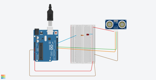
I have begun work on the hat, as evidenced by the attached pictures and progress is good. I have rigged up a simple circuit as a proof of concept. It simply keeps a light on while the sensor is not detecting anything, and turns it off if the detector detects something in its way (if you are touching your face)
It works, ish, however, not very well at this stage. I think I need to figure out the exact place to put the sensor to detect. It may also be a case of rigging up multiple sensors to the hat, potentially some to the sides to detect better. We will have to see.
For now it works and I hope to add the servos soon to get a good smack going, or some other device to stop you touching your face.
Here is the hat!
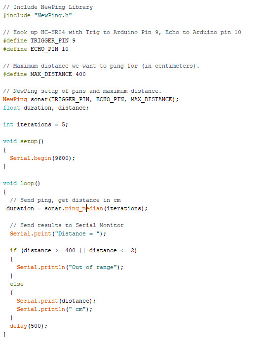
Here is the code!
// Include NewPing Library #include "NewPing.h"
// Hook up HC-SR04 with Trig to Arduino Pin 9, Echo to Arduino pin 10 #define TRIGGER_PIN 9 #define ECHO_PIN 10
// Maximum distance for ping (in centimeters). #define MAX_DISTANCE 400
// NewPing setup of pins and maximum distance. NewPing sonar(TRIGGER_PIN, ECHO_PIN, MAX_DISTANCE); float duration, distance;
//LED STUFF
const int ledPin = 13; //LED is in pin 13 int ledState; //what state is the LED in (on/HIGH or off/LOW)
void setup() { Serial.begin(9600); //uhhhhhhh pinMode(ledPin, OUTPUT); //set the LEDpin (13) to be the output }
void loop() { // Send ping, get distance in cm distance = sonar.ping_cm();
// Send results to Serial Monitor Serial.print("Distance = ");
if (distance >= 150 || distance <= 2) { Serial.println("Out of range"); //if its beyond my face and hasn't registered a block, it is out of range and sets the LED to on
if (ledState == LOW) { ledState = HIGH; }
} else //if you detect a dirty corona virus ridden hand near the sensor { Serial.print(distance); //print the distance Serial.println(" cm");
if (ledState == HIGH) { //set the LED to off ledState = LOW; } } digitalWrite(ledPin, ledState); //Actually set the LED to whatever state it has been set too depending on if it detects a hand or not delay(500); }
Here is a circuit diagram!
Here is a video of it in action! (without a hat)
https://youtu.be/Etip8XAyJUA
Thank you!
0 notes
Text
Anti-Coronavirus Hat: Preliminary Tests
Struggling for an idea for a project, I couldn’t get the idea of the hat that stops you from touching your face out of my head.
My attempts at an arduino, or more likely raspberry pi that uses AI and a camera to detect you touching your face were stopped when I realised not only how bad of an idea that is, but also that using machine learning AI is far out of my abilities for now. I instead thought of alternative ways to detect when you touched your face and decided to test ultra sonic sensors. I ordered 4 of these, as they seemed most suitable for my project; they also seemed very versitile so I could use them for something else if the hat doesn’t work.
They arrived in a nice bit of packaging and I quickly got to work researching them.


Its unfortuntely hard to see due to the quality of my phone camera, but the labels from left to right are Gnd(Ground), Echo(Detects the returning signal), Trig(Fires the signal to bounce back off a surface) and Vcc(Power input from the 5V pin).
They are very simple to set up and very simple to use. The company even provide information and a basic script to get it working. I would reccomend them highly, the only issue is that one of them didn’t work very well, as can be seen in the first video. The only other one I have tested works flawlessly however.
https://youtu.be/-Aqdhmb8INI
https://youtu.be/XXD55zpMaIo
The videos show the simple set up required to get started.
Using the time it takes to recieve the signal back, the newping library function:sonar.ping calculates the distance from the object using the equation Distance = Speed/time. The speed is simply the speed of sound as it is an ultrasonic sensor. Divide the result by two (as the distance would otherwise be calculated with the time it took to reach the object and get back) and you have the distance. In the code, sonar.ping_median takes the average of many readings, removing any invalid ones then prints the distance to the serial monitor.
----------------------
With a set up like this, I hope to be able to rig a simple system up that does something when the echo is detected, I think I’ll try a simple LED flash first and then figure out what would work best.
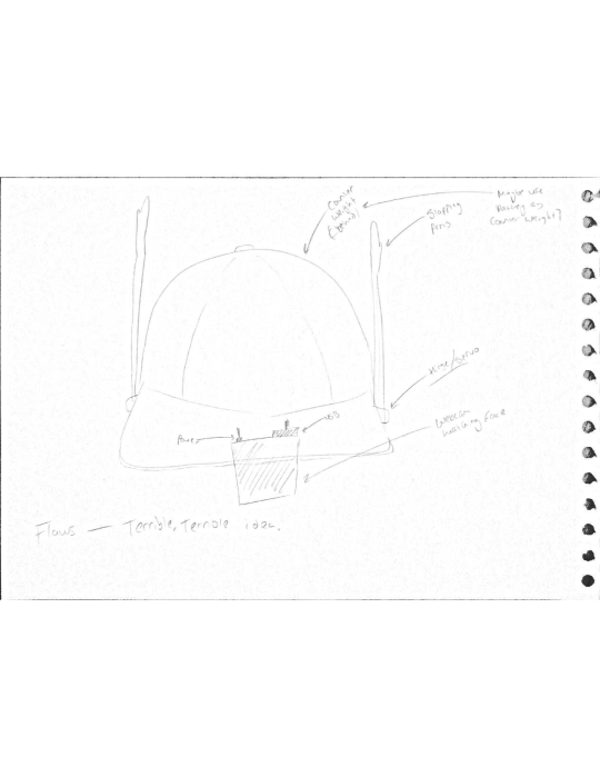
As for the hat. In my first designs I drew a baseball hat for no reason other than that is the hat that comes to mind when I think ‘hat’. Simple drawing and planning shows that this design of hat is not suitable for this, what hat might be though? What hat is large and sturdy enough to hold all the required components with somewhere to put sensors in front of your face? Luckily, I solved that problem in october of last year when I decided to dress as a cowboy for halloween.

With any luck this hat will work perfectly. I think I’ll put the power supply and arduino in the bowl in the top, tape or somehow stick the sensors to the brim and whatever it will be to stop the user touching their face to either side.
I have high hopes for this project now all the parts are here and I look foward to working on it.
0 notes
Text
Physical Computing - Experiments Portfolio 1
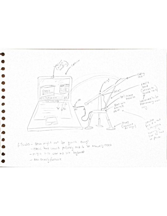
phoMy initial idea has mostly fallen through as the technology required is out of my depth. I wanted to create a device to watch the users face and recognise when they were about to touch thier face (against government advice) then slap the user to stop them from touching their face and hopefully pavlov them into never touching their face, therefore single handedly curing the coronavirus and going down in history as a hero for humanity.
Unfortunately, the technology required to recognise the users face and hands does exist, it is just very complex and not an area I have studied before.
I have attached a few inital sketches for ideas I had, one terrible idea for a hat mounted slapping system and a slightly less terrible desk mounted one.
0 notes
Photo

My infographic on the history of the Gameboy
My infographic is a brief look into the history of the Gameboy, created by Nintendo. It uses pixel art of the different types of Gameboy to show visual differences as well as to add colour and break up the text. The information mostly revolves around the technology inside them and the success of them as a product as well as well known games on that specific device. It is laid out in chronological order with the first Gameboy at the top in 1989 and the final one at the bottom in 2005.
___
References:
Nintendo Co., Ltd (2014) Consolidated Sales Transition by Region. Available at: https://web.archive.org/web/20140201192958/http://www.nintendo.co.jp/ir/library/historical_data/pdf/consolidated_sales_e1312.pdf (Accessed: 25/03/2020).
Buisness Wire (Jan 9, 1995) Color it loud with hot new Game Boys; Game Boy reflects players own style with five exciting new colors. Available at: https://web.archive.org/web/20131102052451/http://www.thefreelibrary.com/Color+it+loud+with+hot+new+Game+Boys%3B+Game+Boy+reflects+players+own...-a016001521 (Accessed: 25/03/2020).
Game Boy Light (no date) Available at: https://www.nintendo.co.jp/n02/dmg/hardware/light/index.html (Accessed: 25/03/2020).
Racketboy (2011) GAME BOY GAMES THAT PUSHED THE LIMITS OF GRAPHICS & SOUND. Available at: http://www.racketboy.com/retro/game-boy-games-that-pushed-the-limits-of-graphics-sound (Accessed: 25/03/2020).
GBA Technical Specifications (2006) Available at: https://web.archive.org/web/20060319151832/http://www.nintendo.com/techspecgba(Accessed: 26/03/2020).
Nintendo Co., Ltd (no date) Game Boy Advance SP Frequently Asked Questions. Available at: https://www.nintendo.com/consumer/systems/gameboyadvance_sp/faq.jsp (Accessed: 25/03/2020).
Cnet (2005) Nintendo Game Boy Micro specs. Available at: https://www.cnet.com/products/nintendo-game-boy-micro/specs/ (Accessed: 26/03/2020).
Cnet (2005) Nintendo Game Boy Advanced SP specs. Available at: https://www.cnet.com/products/nintendo-game-boy-advance-sp/specs/ (Accessed: 26/03/2020).
Nintendo GameBoy/GameBoy Pocket (no date) Available at: https://www.consoledatabase.com/consoleinfo/nintendogameboy/ (Accessed: 25/03/2020).
Technical data (no date) Available at:https://www.nintendo.co.uk/Support/Game-Boy-Pocket-Color/Product-information/Technical-data/Technical-data-619585.html (Accessed: 25/03/2020).
0 notes
Text
Physical Computing - Session 2
This week, we expanded upon last weeks teaching by introducing light-dependent resistors (LDRs) or photoresistors to our circuits.
These increase or decrease resistance through the circuit depending on how many light photons are hitting the detector. The more light, the less resistance. Of course, this can be used simply to increase or decrease resistance, the real usage comes in when a potential divider is used to measure the exact amount of resistance, feeding this back into the Arduino allows almost anything to be changed based on how much light is being shone onto the LDR.
A potential divider is a circuit or part of a circuit that, by using two resistors, one of which you know the resistance of, allows you to measure the resistance of the other resistor. If you place an ADC before and after the unknown resistor you can measure the voltage difference and therefore the resistance. The Arduino then takes this value and allows you to put it into code.
In my experiment, I used this value to increase or decrease the flashing speed of an LED depending on how much light was hitting the LDR. This can be seen in action in the video below
https://youtu.be/gQ-85DniNS4
The code is here:
---
int sensorPin = A0; // select the input pin for the LDR int ledPin = 13; // select the pin for the LED int sensorValue = 0; // variable to store the value coming from the sensor
void setup() { pinMode(ledPin, OUTPUT); //sets pin 13 as the output pin }
void loop() { // read the value from the sensor: sensorValue = analogRead(sensorPin); //read the value and put it into sensorvalue as an analog value // turn the ledPin on digitalWrite(ledPin, HIGH); // stop the program for <sensorValue> milliseconds *10 for clarity: delay(sensorValue*10); // turn the ledPin off: digitalWrite(ledPin, LOW); // stop the program for for <sensorValue> milliseconds * 10 for clarity: delay(sensorValue*10); }
---
I also attempted to use a potentiometer as another form of input, instead of the LDR but struggled to get it working. I hope to figure this out properly later!
0 notes
Text
My first foray into arduinos and physical computing
I have had an arduino for several years in a ‘build your own robot arm kit’ but never got around to making it as I didn’t know what to do with the arduino. At the very least I hope this module teaches me enough to finally getting around to making it.
Simply looking at the prebuilt example scripts taught me enough to get lights flashing simply. At first I had blue and red lights flash in sequence like the lights on a police car. This was fairly simple. I then tried to add a light that faded in and out which is where things got complicated. Firstly I was using DigitalWrite, when I needed to use AnalogWrite in order to have different power sent to the LED other than just ‘all’ and ‘none’ and then I had issues where to put the code.


The final version didn’t work 100% as the light only changes between the flashes of the red and blue, not independently, but I am really looking forward to learning more about arduinos.
0 notes