
Last Seen Blogs


Text
Theoretical Readings
1. Prototyping for Architects by Mark and Jane Burry
The Burry reading was very interesting in its discussion on the importance of prototypes. Creation of the prototype is a process of its own that generates a scaled version of what is to come. It first helps the architect discover things they might want to adjust from the design drawings and creates a sense of “workflow” that allows “room for further detail and development” (Burry, 74). Developing a prototype can be related to the Descartes reading which discusses geometrical significance. Lines are a major aspect of architecture as they generally make up the designs of buildings and floor plans. Descartes writes that, “making no distinction between the known and unknown lines, we must unravel the difficulty in any way that shows most naturally the relation between these lines” (Descartes, 6-7). In architecture, lines are an element of a whole and experimenting with the formation of lines (through thickness, length, orientation, etc.) is one of the early stages of producing anything, including a prototype. These ideas can also be related back to the Moe and Smith reading. The upbringing of different software in the field represents a much more efficient “approach to modelling” (Burry, 144) and architects need to be able to adapt to said changes.
2. Digital Fabrications: Architectural and Material techniques by Lisa Iwamoto
In Lisa Iwamoto’s Digital Fabrications: Architectural and Material Techniques (Folding), Iwamoto discusses the digital-fabrication process and its connection to folding. The concepts of folding and its ability to generate “stiffness and rigidity, [and] self-support” (Iwamoto, 61) can be connected to the first weeks exercise where a sheet of paper was folded to create a hyperbolic paraboloid. Iwamoto’s arguments are interesting because they strive to implore the idea that folding is a much greater concept than what it is given credit for. Furthermore, while folding has been a traditionally “craft-based practice”, often only used in terms of creating small scale forms, advancements in technology have opened a path for folding – allowing entrance to architectural forms on a grander scale. The method of folding or rather, unfolding, is now present in software that allows us to deconstruct a 3D object into 2D pieces so that it can be put together in the most efficient and sensible way possible. Folds as an “operational system” can create new spatial conditions but they can also function as a means of ornamentation or “conventional construction”. This is shown in the Walker Art Center Expansion example where the creases create a “crinkled façade” but also “eliminates unanticipated oil-canning” (64).
2 notes
·
View notes
Photo


Exercise 5, Part II: Solid to Surface
In part II of exercise 5, we were asked to use the vacuum form to create a molded surface from the milled forms we created prior, using recycled PETG. First, the milled volume was placed in the center of the vacuum form sheet bed, then it was lowered. The PETG sheet, cut to size, was then placed in the form and a heated. At first, the desired heat was evaluated through just looking at the temperature number, but we often found ourselves looking directly at the plastic to determine whether it was ready (the plastic would bubble when hot but it was important to keep it from getting too hot, as it could tear). When it was determined that the plastic was done heating, the bed with the milled form would push up into the plastic which was able to mold to the form due to its high plasticity while hot.
The images presented show how the plastic was able to capture the details of the milled forms (and how it may not have done so). When additional materials were added, such as a napkin or tinfoil, the details of that material were replicated in the vacuum form. This part of the exercise can again be related back to Deplazes discussion on plastic and how different materials have different “requirements they have to meet” (Deplazes, 331). There are, of course, limitations in the ways in which plastic can be used, as there are limitations to using any material. If the plastic was not hot enough, it was unable to fully capture the textures and shapes of the milled form. If it was too hot, it would tear. Furthermore, issues were encountered in the removal of the plastic from the form, as if there were any areas on the sides of the form that extruded out and back in, the plastic would mold around these parts making it very difficult to remove.
Team Members: Halima Matthews, Tatijana Stewart and Annette Chu
Sources: Deplazes, Andrea. Construction Architecture: Materials, Processes, Structures: A Handbook (4th Edition). Berlin: Birkhauser, 2005.
0 notes
Photo


Exercise 6: Robotic ToolPaths (Space Frames/Diamonds and Diagonals)
This week’s exercise involved using a robot arm to replicate a path that was created using Rhino and Grasshopper. A camera with extended exposure time would process the path of the LED light on the arm and was able to capture the image produced by the path. One of the focuses of each of our images produced was to explore depth through pulling points on the Grasshopper definition in various directions. Through doing this, the image would remain the same when you look at it straight on, but take on a completely different form when the view was from the side or the top. Tatijana’s curve depicts a face which is very apparent in the straight on photo where nothing was adjusted. In the following image, she plays with the zoom and angle of the camera lense in order to produce the sense of depth. It is more difficult to tell what the image is but when looking at the intended form and the form that produces depth, the connection can be made that they are the same form. Annette’s curve is less of a precise form but still depicts depth through the use of two colors. The yellow LED light slightly offsets the red, making it appear as a three-dimensional form. My form was supposed to take the shape of a house but the low amount of points on the grasshopper definition distorts the image. The LED light image might not show the depth as well, but by looking at the Rhino screenshots you can see the various forms that come out of pulling a few points in different directions.
In Deplazes’ discussion on space frames, he notes that they “consist of delicate linear members” (Deplazes, 136). In discussing “diamonds and diagonals” Deplazes notes that “horizontal loads can be accommodated with a single structure of linear members seemingly without any hierarchy, but equally because the network takes on an ornamental quality” (Deplazes, 137). These linear members are not dissimilar to the movements of the robot arm, which follow the paths of the curves created in rhino and grasshopper. It starts at one point and moves to the next and each movement is important to the final produced form, which gets rid of the hierarchy that Deplazes mentions and makes each point a vital point to the desired form. Furthermore, the ornamental aspect that Deplazes mentions shows in that the generated forms from the light paths create something arbitrarily unique and intriguing to the eye in a similar manner as many “space frames” do, like in Herzog and de Mueron’s Prada store in Tokyo.
Team Members: Halima Matthews, Tatijana Stewart and Annette Chu
Sources: Deplazes, Andrea. Construction Architecture: Materials, Processes, Structures: A Handbook (4th Edition). Berlin: Birkhauser, 2005.
0 notes
Photo
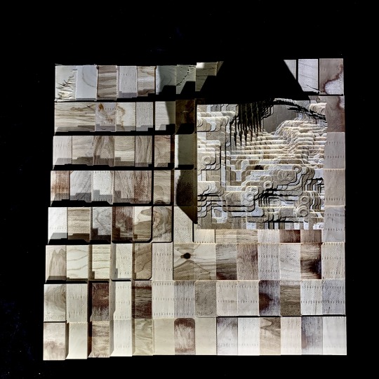


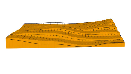
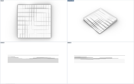
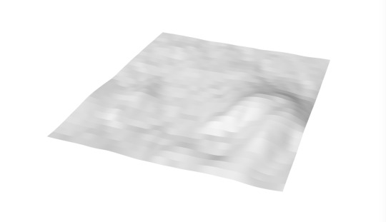


exercise 5. part 1 - surface to solid
In this exercise, topographical data points were downloaded from the NASA Shuttle Radar Topography Mission (SRTM) database and translated into a digital surface. Then, this surface was put into a grasshopper definition which extruded the surface from a given plane in order to generate a solid. This solid was milled on the CNC router through a materially reductive method, in which an instruction set consisting of coordinates (generated through RhinoCAM) informed the mill’s path to cut away material from the solid block of 20″x 20″x 3″ laminated wood. This study prompts attentiveness toward the implications of relative scale throughout all stages of design and fabrication processes, both how scale functions as a generator of unknown variability and as design tool.
selection of topography - scale of earth v. scale of the product, earth’s surface is actually very flat relative to size of sphere on which it sits. This flatness reads even at the scale of a single latitude-longitude swatch of extracted data points (NASA Shuttle Radar Topography Mission). In order to combat this scale and define an area in the lat-long that had appropriately variable elevation, the area extracted for the surface had to be reduced to 1:100 of the original area.
adjustment of parameters of gh determined solid - once the data points had been translated into a surface using the first grasshopper (gh) definition, the baked surface that came as a result was input into the new “chunky surface” definition in order to generate the solid. At this point, various adjustments to parameters within the gh definition such as min/max count, aspect ratio, or even a surface rebuild (not within the gh definition, but rather command within rhino onto the surface) all yielded variable conditions of the base unit, or the smallest flat element within the larger topography. Object 1 has many large, rectangular units as a result of a long series of arbitrary aesthetic adjustments, which equates to lower fidelity to the variability within the original surface and a more abstracted reading. Object 2 was not subjected to any parameter changes, and therefore exhibited much smaller and more square elementary units that were able to accommodate the true topography more accurately.
translation render-to-mill - in this final step, the implications of tool capabilities and limitations were made very apparent. On object 1, the size of the milled object, though it looks much less complex and of lower variability than object 2, took much longer to mill (3 hours opposed to 30 min) due to the fact that it was 2.5x the length and width of object 2. This is of practical consideration when constructing multi-step and piece models in which material efficiency/cost and time/labor costs are of relevance. In fact, it was due to time/labor constraints that the decision was made to mill object 2 at the smaller size. This resulted in some movement of the block during the milling process, as the shear forces were strong enough to begin to dislodge the form from its constraints (small blocks visible in fig. 8). Additionally, for object 1, the angle of approach of the end mill was set to 45 degrees for the finishing portion of the job (versus 30 degrees for object 2). This angle, accompanied by the low relative depth of each unit to those surrounding compared to its surface area might have been the cause for some of the shearing forces that delaminated some of the object’s top layers (visible in fig. 9, large flat space in bottom right corner of object 1). On the other hand, the large elementary units paired well with the .5 inch end-mill, in that the corner moments, though still rounded in actuality, look very angular at the scale of the unit whole. In contrast, on object 2, due to the fact that the elementary unit was about .5″x.5″, the reading of this corner bevel resulted in a much more jagged and organic looking result. The scalloping and sometimes fully circular moments on the final product inadvertantly begin to allude to the mountainous nature from which this solid was derived, all due to a matter of relative scales.
3 notes
·
View notes
Photo


Exercise 4, Part 2: Zund
The process of cutting and combining the forms that we designed using Rhino and Grasshopper exposed us to a series of conditions that we observed, and put into context the discussion of the importance of considering all of the elements that might go into creating a form. One thing that we discovered was the effect of the geometry of the tab shape in holding the object together. If the geometry does not allow for the tabs to latch to each other, the form is loose and the tabs continuously slip. If they are too tight, it might change the forms shape or simply be impossible to put together. The limitations of the material, plastic, as Deplazes notes, “has to be content with a neutral quality of substance, resistance…[it is] lost between the elasticity of rubber and the hardness of metal” (Deplazes, 150). This is to say that the difficulties encountered are not only the result of the geometry, but of the material itself. For the most part, plastic can be configured to a desired shape quite easily. However, there are always limitations always occur when trying to produce one goal and the thickness of the plastic limits its plasticity. In connection to the exercise, some of the designed forms would not hold or come together as planned because of the fact that the plastic could only bend so much. Furthermore, in terms of how the material affects appearance, the plastic used had another thin layer which, if removed, changed the opacity of the plastic, in turn, affecting the entire portrayal of the object.
Objects and images were produced by Halima Matthews and Tatijana Stewart.
Andrea Deplazes (ed.) “Plastic on the Threshold of Architecture” in Constructing Architecture: Materials, Processes, Structures: A Handbook. Berlin: Birkhauser, 2005.
0 notes
Photo


Exercise 4, Part I: Unrolling a Developable Surface
Exercise 4 uses Rhino and Grasshopper to create a 3D surface through a curve. First, a curve was generated and then revolved a certain amount of times through grasshopper to create a form. Following this, another curve was implemented to serve as the tabs on the form which when unfolded, created multiple surfaces that could be interconnected or disconnected with (general) ease. One of the important elements in successfully achieving this exercise was creating tab shapes that would work within the 3D surface shape limits. I encountered some of the issues that the exercise document mentioned might occur. For instance, my tabs were inside out and did not actually connect to the form’s curve at first. I found that with using the troubleshoot methods advised, such as switching the direction with the “Dir” command and shifting the curve away from the origin point (0,0), I was able to resolve these issues. It would also be difficult to create these 3D shapes from plastic without separating them into multiple sheets first. This speaks to the idea that Deplazes presents, which is to say, that plastic has its limitations despite its lack of form. Matti Suuronen’s “Futuro” is a great comparison that shows large panels of prefabricated plastic precisely pieced together, similar to the structure of the exercise (Deplazes, 159).
References:
Deplazes, Andrea. Construction Architecture: Materials, Processes, Structures: A Handbook. Berlin: Birkhauser, 2005.
1 note
·
View note
Text
Columbia Business School Construction Site Visit
The construction of Columbia’s business school can be connected to the Deplazes text through examining the material being used and the structural forms created. One thing that can be said about the building immediately, which Deplazes notes about building processes in general, is that “the building process has become more organized, and the construction itself now shows traces of the modularity of the formwork layout and large sheet steel prefabricated formwork panels” (Deplazes, 58). Just by looking at the facade of one of the buildings, the form starts to reveal itself through eliminated spaces of glass and the structural shape of the steel. From images that I took, it seems as though the beams throughout the building are bolted and the “end plates are welded to the beam” (Deplazes, 124) as shown in the image.

Looking up from the bottom, the structural frame appears to resemble a combination of trapezoidal profile metal sheets and reinforced concrete topping (a mixture of D2 and D3) (126). I am unsure whether or not the metal sheets are permanent or for supportive purposes during construction, but I assume that they are permanent frameworks because the flooring above them is concrete and below them are supportive beams, creating the “composite action between concrete slabs and steel beams” (Deplazes, 126).

Lastly, one of the takeaways that I really found interesting was the slab of material between the columns that run through the building and the columns on the roof. I forget what the material was exactly called, however its purpose was to prevent heat from escaping the entire building through those columns. It is amazing to me that something that seems so small and mundane has such an important effect on the insulation of a building.

References:
Deplazes, Andrea. Construction Architecture: Materials, Processes, Structures: A Handbook. Berlin: Birkhauser, 2005.
1 note
·
View note
Photo


Exercise 3: Responsive Surface (Flat) ( Part I: Surface responds to a Point, Part II: taking a line for a walk on your responsive surface)
Exercise 3 focused on the creation of a plane using a specifically arranged set of lines that were then subdivided into a series of units, then cut using a laser on chipboard. The variety in size of the cutouts on the plane creates an interesting pattern and creates a spatial relationship that was non-existent before the cutting. Deplazes writes, “It is only the openings in the walls that create a spatial reference with the outside world” (266). While an extreme version, the exercise result resembles the appearance of a plan with a series of spatial relationships (maybe a floor plan with many “rooms” or a façade with many “windows”). Deplazes also speaks on the manipulation of light in talking about open louvres that “can be rotated into position to reflect the sunlight” but also “permit a view of the surrounding countryside” (292). If held underneath a form of light and the position of the exercise piece is altered, the shadows that are created follow suit, with some extending further in one direction than the other. It is interesting to note the forms that can be reproduced through shining light on a plane with openings of various sizes and thicknesses.
References:
Deplazes, Andrea. Construction Architecture: Materials, Processes, Structures: A Handbook. Berlin: Birkhauser, 2005.
0 notes
Text


Exercise 2: (Parts I & II): Drawing w/ algorithms - Sol LeWitt tutorial
This exercise presented a way in which a simple geometric shape, such as a circle or a rectangle, can create a complex and intriguing design. The system of multiplying and layering used for the exercise can be compared to systems used in architecture. One way in which creating these designs can be evaluated is through Deplazes discussion on load-bearing compression structures. Barrel vaults are described as “nothing other than an arched shaped curved surface, or rather a succession of parallel arches” (253). After trimming the plane, the design can be deciphered as a series of arches going up, down, left and right, overlapping one another; a simple geometric form that when combined, allows for a sturdy structure. Furthermore, dome structures when cut in plan can be represented as a series of circles. Personally, using grasshopper was difficult as some of the results did not appear as expected, however, it is interesting to note the several different ways that manipulation of one element of the system affects the entire design. This shows the importance of experimentation in the design process and ways in which tools such as grasshopper have the ability to plan out structural systems, such as domes and vaults, through implementing and repeating precise, geometric forms.
References:
Deplazes, Andrea. Construction Architecture: Materials, Processes, Structures: A Handbook. Berlin: Birkhauser, 2005. --> Vaulted Loadbearing Structure in Solid Construction
0 notes
Photo


Exercise 1: Folding paper - Hyperbolic Paraboloid
Exercise 1 required folding a piece of paper a specific amount of times and in specific ways that when unfolded, created a hyperbolic parabaloid. The exercise can be related to Deplaze’s text, Constructing Architecture, in that it requires a “range of criteria” that do not seem to lead anywhere until the project is completely finished. The folding plates system discussed by Deplazes is very relevant to the exercise as well, as it makes up a majority of the steps. Deplazes describes a saw tooth roof system, a folding system, which he categorizes as a system for directing light and as a sculptural element. The final folds in the process of creating the hyperbolic parabaloid resemble the “sawtooth roof” that is found in Gigon & Guyer’s Lineer Museum in Appenzell (CH) (Deplaze, 221). When the paper is unravelled, it is able to hold its shape on its own, showing the stability effects of the folding plates system and the sawtooth roof. Additionally, the images shown slightly reflect/distribute light in the presentation of the shadow, but more effectively represent the sculptural elements through “an expressive silhouette” (Deplazes, 221). The steps required to fold a hyperbolic paraboloid only make it seem as though the paper is is straying further away from the intended form. However, once the steps are completed, the form becomes apparent.
Source: Deplazes, Andrea. Construction Architecture: Materials, Processes, Structures: A Handbook. Berlin: Birkhauser, 2005
1 note
·
View note