
Don't wanna be here? Send us removal request.
Statistics
We looked inside some of the posts by heavydutymachinerepairguide and here's what we found interesting.
Average Info
Notes Per Post
0
Likes Per Post
0
Reblog Per Post
0
Reply Per Post
0
Time Between Posts
2 days
Number of Posts By Type
Text
17
Last Seen Tumblr Blogs


Fun Fact
BuzzFeed published a report claiming that Tumblr was utilized as a distribution channel for Russian agents to influence American voting habits during the 2016 presidential election in Feb 2018.
Text
Perkins 2806F Engine Inlet and Exhaust Valve Springs - Remove and Install
This article introduces Perkins 2806F Engine Inlet and Exhaust Valve Springs - Remove and Install Removal Procedure Start By: a. Remove the electronic unit injectors. Refer to Disassembly and Assembly, "Electronic Unit Injector -Remove"for the correct procedure. NOTICE: Keep all parts clean from contaminants. Contaminants may cause rapid wear and shortened component life. Perkins EST Diagnostic Adapter- High Quality NOTICE: Note: Valve springs must be replaced in pairs for the inlet valves or the exhaust valves of each cylinder. If all valve springs require replacement the procedure can be carried out on two cylinders at the same time. The procedure can be carried out on the following pairs of cylinders. 1 with 6, 2 with 5 and 3 with 4. Ensure that all the valve springs are installed beforechanging from one pair of cylinders to another pair of cylinders Personal injury can result from being struck by parts propelled by a released spring force. Make sure to wear all necessary protective equipment. Follow the recommended procedure and use all recommended tooling to release the spring force. 2023A& 2022A Perkins EST Electronic Service Tool Diagnostic Software Full Provide Installation Service 2. Install Tooling (B) into the electronic unit injector sleeve. Secure Tooling (B) with unit injector clamp (1) (not shown). 3. Tighten the nut of Tooling (B) until valve keepers (3) are released from valve rotators (4). Note: Ensure that valve stem seals (7) are not damaged. 4. Remove valve keepers (3) from valve rotators (4). 5. Loosen the nut to release the pressure on Tooling (B). Remove unit injector clamp (1) (not shown). Carefully remove Tooling (B). 6. Remove valve rotators (4) from valves (2). 7. Remove outer valve springs (6) and inner valve springs (5). 8. Remove washers (8) from the valve guide. 9. If necessary, repeat Step 1 through Step 8 toremove remaining the inlet and the exhaust valve springs.
Perkins Engine ECM ECU Flash Files Collection Download
0 notes
Text
312D2 and 313D2 Excavator 3054C Engine System Pressure- -Release
This article mainly introduces 312D2 and 313D2 excavator 3054C engine System pressure- -release
Caterpillar 18 Digits Factory Password Calculator One-Time Calculate Service
Before repairing the hydraulic circuit, the hydraulic pressure in the hydraulic circuit must be released. The pressure of this hydraulic circuit shall be released before disconnecting or removing any hydraulic lines from the following hydraulic circuit.
Arm hydraulic loop
Bucket bar hydraulic loop
Bucket hydraulic loop
Turn the hydraulic circuit
Drive the hydraulic circuit
Attachment Hydraulic circuit (if provided)
Pilot hydraulic circuit
Reflow hydraulic circuit
Note: Refer to the Disassembly and Assembly manual for additional information on the specific hydraulic circuit components.
Hydraulic pressure release for the multiple hydraulic circuits
The pressure of rolling hot oil or hydraulic oil can cause harm to personnel.
After the engine stops, the hydraulic oil pressure will remain in the hydraulic system. Serious injury may occur without prior pressure release prior to repairs to the hydraulic system.
When removing the components or lines of the hydraulic system, ensure that all work tools are lowered to the ground
On, and the hydraulic oil temperature is already cold. Remove it only when the engine is stopped and the filler cap is cooled to freehand touch.
pay attention to
During inspection, maintenance, testing, adjustment and repair, the oil must be performed. Prepare a suitable container to collect fluid before opening any compartment or dismantling any stored parts.
For applicable tools and supplies for collecting and filling the fluid on Cat products, refer to special publications, NENG2500, "Agent Repair Tool Catalogue".
Dispose of all liquids in accordance with local regulations and requirements. Caterpillar ET 2024A & 2023C & 2019C Electronic Technician Diagnostic Software Download and Installation
Follow the following steps to release the hydraulic pressure from multiple hydraulic circuits of the main hydraulic system.
1. Park the machine on the horizontal ground.
2. Fully withdraw the bucket rod cylinder connecting rod. Adjust the bucket position so that the bucket is parallel to the ground. Lower the boom until the bucket falls horizontally on the ground. See the illustration 1.
3. Turn off the engine.
4. Turn the engine start switch to the on position, but not starting the engine.
5. Place the hydraulic start control lever in the unlock position.
6. Move only the joystick or pedal of the repaired hydraulic loop to the full position. This will then release only the high pressure in this hydraulic loop. This will also release any pressure that may exist in the pilot hydraulic circuit.
Note: If the repaired hydraulic circuit needs to start the operating switch, start the corresponding operating switch in the hydraulic circuit.
7. Place the hydraulic start control lever in the locked position.
8. Start the engine.
9. Place the hydraulic start control lever in the unlock position. In this step, do not move any joystick or pedal away from the neutral position. In this step, do not turn in any switches.
10. Move the hydraulic start control lever back to the locking position.
11. Turn off the engine.
12. Repeat steps 4 to step 11 respectively for other hydraulic circuits that require maintenance.
13. After releasing the hydraulic pressure in each target hydraulic loop, place the hydraulic start lever in the locked position.
14. Turn the engine start switch to the off position.
15. Slowly release the filler plug on the hydraulic tank to release the pressure. The fill port plug shall remain loose for at least 45 seconds. This releases the pressure that may be present in the return hydraulic circuit.
16. Tighten the fill port plug on the hydraulic tank to achieve the specified torque.
17. The pressure in the multiple hydraulic circuits requiring repair is now released, and the lines and components can be disconnected or removed from these hydraulic circuits.
0 notes
Text
This article mainly introduces how to perform brake exhaust operation on Isuzu vehicles
ISUZU IDSS MX2-T Diagnostic Adapter System Support G- IDSS/US-IDSS/E-IDSS (Included DHL Shipping)
Air in the brake hydraulic circuit will result in dangerous reduced braking efficiency.
The brake hydraulic circuit must be bled whenever the vehicle has been operated with the reservoir brake fluid level at an excessively low level or any time the brake pipes have been disconnected in the course of brake servicing.
The brake bleeding procedure requires the cooperative action of two men.
Brake Bleeding Procedure Bleed the brake hydraulic circuit in the following se- quence. LHD Left-hand rear wheel (vehicle equipped with ABS) → Right-hand rear wheel → DSPV or LSPV → (If so equipped) → Right-hand front wheel → Left-hand front wheel RHD Left-hand rear wheel (vehicle equipped with ABS) → Right-hand rear wheel → DSPV or LSPV (If so equipped) → Left-hand front wheel → Right-hand front wheel

1. Check to make sure that the service area is well ventilated. Apply the parking brake firmly. Start the engine and allow it to run until the vacuum pressure rises suf- ficiently.
Notice: Brake booster (master-vac) will be adversely effected if bleeding operation is performed without running engine. If the vehicle is equipped with ABS, be sure to remove the ABS fuse (60 A) from the fuse box before beginning the air bleeding procedure. If this is not done, air is not bled completely from ABS unit, so that ABS unit will be broken. (Be sure to install the ABS fuse (60 A) in speci- fied position when the air bleeding procedure is complet- ed.)
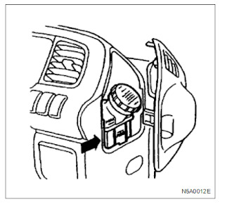
2. Fill the brake fluid reservoir (1) up to the “MAX” lev- el with clean brake fluid.
It may be necessary to replenish the brake fluid reservoir several times during the bleeding proce- dure to maintain the required level of brake fluid.

Notice: Pour the brake fluid carefully so as not to produce air bubbles. 3. Remove the right hand rear wheel cylinder (left hand rear wheel cylinder if ABS is equipped) bleed- er screw rubber cap and wipe it clean. 4. Connect one end of a vinyl tube (2) to the bleeder screw. 5. Insert the other end of the vinyl tube into a trans- parent container approximately 1/3 full of brake flu- id. 6. Depress the brake pedal (3) slowly 3 times and hold it depressed.

7. Loosen the bleeder screw (4) approximately 1/2 of a turn.
This will release the brake fluid with air bubbles into the transparent container (5).

9. Slowly release the brake pedal.
10. Replace the bleeder screw rubber cap.
Notice:
In order to bleed the air completely from the brake line, repeat the above procedures.
Bleeding of the brake fluid circuit should be performed for front wheel 10 times or more, for rear wheel 15 times or more.
11. Repeat Steps 3 through 10 for each bleeder screws as mentioned before.
12. After the air bleeding procedure is finished in all wheels, depress the brake pedal, and verify wheth-
04.2023 ISUZU E- IDSS Diagnostic Software Download and Installation Service
er there is no abnormality in operation of the brake system. 13. After the air bleeding procedure for individual wheel is completed, inspect the fluid level of the reservoir tank. If it is insufficient, replenish brake fluid. Do not overfill above “MAX” level. 14. Stop the engine.
0 notes
Text
Caterpillar 312D2 and 313D2 Excavator 3054C Engine Disassemble and Assemble
This Article Mainly Introduces Caterpillar 312D2 and 313D2 Excavator 3054C Engine Disassemble and Assemble
Caterpillar ET 2024A & 2023C & 2019C Electronic Technician Diagnostic Software Download and Installation
System pressure- -release
SMCS - 4000-553-PX; 4350-553-PX; 5050-553-PX; 6700-553-PX
Steps to release the pressure
Before repairing the hydraulic circuit, the hydraulic pressure in the hydraulic circuit must be released. The pressure of this hydraulic circuit shall be released before disconnecting or removing any hydraulic lines from the following hydraulic circuit.
Arm hydraulic loop
Bucket bar hydraulic loop
Bucket hydraulic loop
Turn the hydraulic circuit
Drive the hydraulic circuit
Attachment Hydraulic circuit (if provided)
Pilot hydraulic circuit
Reflow hydraulic circuit
Note: Refer to the Disassembly and Assembly manual for additional information on the specific hydraulic circuit components.
Hydraulic pressure release for the multiple hydraulic circuits
The pressure of rolling hot oil or hydraulic oil can cause harm to personnel.
After the engine stops, the hydraulic oil pressure will remain in the hydraulic system. Serious injury may occur without prior pressure release prior to repairs to the hydraulic system.
When removing the components or lines of the hydraulic system, ensure that all work tools are lowered to the ground
On, and the hydraulic oil temperature is already cold. Remove it only when the engine is stopped and the filler cap is cooled to freehand touch.
pay attention to
During inspection, maintenance, testing, adjustment and repair, the oil must be performed. Prepare a suitable container to collect fluid before opening any compartment or dismantling any stored parts.
For applicable tools and supplies for collecting and filling the fluid on Cat products, refer to special publications, NENG2500, "Agent Repair Tool Catalogue".
Dispose of all liquids in accordance with local regulations and requirements.
Follow the following steps to release the hydraulic pressure from multiple hydraulic circuits of the main hydraulic system.
1. Park the machine on the horizontal ground. Caterpillar 18 Digits Factory Password Calculator One-Time Calculate Service
2. Fully withdraw the bucket rod cylinder connecting rod. Adjust the bucket position so that the bucket is parallel to the ground. Lower the boom until the bucket falls horizontally on the ground. See the illustration 1. 3. Turn off the engine.
4. Turn the engine start switch to the on position, but not starting the engine.
5. Place the hydraulic start control lever in the unlock position.
6. Move only the joystick or pedal of the repaired hydraulic loop to the full position. This will then release only the high pressure in this hydraulic loop. This will also release any pressure that may exist in the pilot hydraulic circuit.
Note: If the repaired hydraulic circuit needs to start the operating switch, start the corresponding operating switch in the hydraulic circuit.
7. Place the hydraulic start control lever in the locked position.
8. Start the engine.
9. Place the hydraulic start control lever in the unlock position. In this step, do not move any joystick or pedal away from the neutral position. In this step, do not turn in any switches.
10. Move the hydraulic start control lever back to the locking position.
11. Turn off the engine.
12. Repeat steps 4 to step 11 respectively for other hydraulic circuits that require maintenance.
13. After releasing the hydraulic pressure in each target hydraulic loop, place the hydraulic start lever in the locked position.
14. Turn the engine start switch to the off position.
15. Slowly release the filler plug on the hydraulic tank to release the pressure. The fill port plug shall remain loose for at least 45 seconds. This releases the pressure that may be present in the return hydraulic circuit.
16. Tighten the fill port plug on the hydraulic tank to achieve the specified torque.
17. The pressure in the multiple hydraulic circuits requiring repair is now released, and the lines and components can be disconnected or removed from these hydraulic circuits.
CAT Caterpillar ET 3 Diagnostic Adapter 317-7485/478-0235 Diagnostic Tool-high quality
0 notes
Text
Doosan DA30 Dump Truck the ECU Wiring Tier2 -Removal
This article introduces doosan DA30 Dump Truck the ECU wiring Tier2 -Removal 2023.07 Doosan DMS-5 Data Monitoring System Diagnostic Software Drain the coolant from the engine as described in the work de scriptions for the cooling system. 2. Wash clean the rocker covers and the area around them. 3. Remove the inlet pipe between the turbocharger and the air cleaner. 4. Remove the air line to the compressor. The air line is located on the left-hand cable duct. 5. Unplug the connectors from the control unit. 6. Remove the rocker covers. On the 12-litre engine the crankcase ventilation must be removed before the rocker cover on cylinder 1 can be removed. Doosan Machine Engine Diagnostic Software Package 2024 One PC Installation
7.Disconnect the cables from the unit injectors. The screws cannot be removed, but they should be unscrewed as far as possible. 8.Mark the cables with the respective cylinder numbers. 9.Remove the cable duct to which the cables are attached. The unscrew the cable bushings in the lower rocker covers and remove the cables. 10.Remove the charge air sensor and its clamps. 11.On engines ftted with an electricallycontrolled fan, separate the connector on the fan ring, which is connected to the solenoid valve.Remove the cable clamps as well. 12.Remove the oil pressure sensor and its clamps. 13.Remove the coolant temperature air sensor and its clamps. Doosan Diagnostic Tool UVIM Support Doosan Excavators High Quality
0 notes
Text
Doosan DA30 Dump Truck engine assembly -Removal
七月 04, 2024
This article introduces doosan DA30 Dump Truck engine assembly -Removal
Doosan Diagnostic Tool UVIM Support Doosan Excavators High Quality
Place the dump truck on level ground and apply parking brake. Apply articulation lock. Turn off main switch in battery case. Raise the dump body and lock it with the safety support. Raise the tiltable cab and lock it with the safety support. Remove bonnet. Drain engine coolant. Look in OPERATION & MAINTENANCE MANUAL chapter 2 for instructions.
WARNING: Never turn off battery main switch when engine is running Never turn off battery mainSwitch when ignition is on Leave battery main switch on for atleast 3 minutes before engine has stopped
DANGER:lace wheel chocks to the front wheel
Take away the cab bolt, left and right hand side. M46 mm Bolt torque: 277Nm
Turn the direction valve on the pump in lifting up position. With the handle, pump and raise the cab
Left side: 1. Disassemble the cab pump unit from the air filter stand. 2. Remove the water hose from the pipe socket. 3. Remove the fuel hoses (3 pcs) and 4. Disassemble hydraulic hoses
Disasssemble the cable to the Air filter sensor and cable to the sensor for the cooling water expansion tank. The unit will have two sensors on T4i/stage 3B (black arrows). Doosan Machine Engine Diagnostic Software Package 2024 One PC Installation
Slack the transmission belt. Detach the Air Cond. compressor with the hoses on, from the engine. Check that all of the clamps are undone. Place the Air condition compressor on the left side while the en gine is dismounted.
Disconnect the hose from the termostat housing and the pipe between the air cooler and engine air inlet. Disconnect bracket for the air pipe and bracket between engine and fan bracket
Disconnect the outlet pipe bend from turbo, and the inlet water hose from the transmission cooler.
Disconnect the retur hose. (Engine - expansion tank) (Quick release coupling) (Front of the engine, view from the right hand side)
Disconnect the urea venting filter
Disconnect the cables between starter motor and the frame
Disassemble grounding cable attached to bracket underneath the engine starter. 2023.07 Doosan DMS-5 Data Monitoring System Diagnostic Software
Disconnect contact on the dynamo.
Remove the cover and disconnect the electrical contact from the engine ECU -S6 control unit Unwind wires from engine to frame
Front- Left and right hand side, disassemble screw on the engine mounting bracket. Assembly torque: 560 Nm (M20 10.9)
Remove clamps and dissasemble hoses connected to hydraulic block (red arrows) 1 2 Drive shaft Remove safety archer. Remove driveshaft between transmission and engine coupling, 1 Assembly torque: 114 Nm 2 Assembly torque: 141 Nm 3 Assembly torque: 141 Nm Disassemble front brake oil cooler hose from the brake cooler circulate pump.
0 notes
Text
JCB Backhoe Loader Power Sideshift - Wear Pad Renewal
This article mainly introduces JCB Backhoe Loader Power Sideshift - Wear Pad Renewal JCB Heavy Duty Truck Diagnostic Tool JCB Electronic Service Tool with JCB ServiceMaster42023.09 Inspection (1000 hours) When the wear pads are worn to 6 mm (0.23 in) or below they should be replaced. It is permissible to rotate the top wear pads 180° to prolong service life, provided the contact surface is more than 6 mm (0.23 in) thick.
Note: If rotating the wear pad the grease nipples will have to be swopped over. Dismantling 1 Park the machine on firm level ground, engage the parking brake and set the transmission to neutral. Lower the loader arms to the ground.
2 Set the carriage fully to end of travel A, shown in centre position for clarity.
3 Lower the bucket to take the weight off the kingpost.
4 Switch OFF the engine and remove the starter key, operate the control levers to vent residual hydraulic pressure.
5 Unlock top lock tab B and unscrew nut C.
6 Remove bolt D through the slot in the rail E.
7 Hydraulic clamp F and washer G should remain in position.
8 Remove plate J and wear pad H. Assembly 03.2024 JCB ServiceMaster4 v24.3.1 Diagnostic Software with SW Files 9 Fit wear pad H, plate J and bolt D.
10 Fit new lock tab B and fit nut C.
11 Set the hydraclamp clearance as described in Sideshift - Hydraclamp Clearance Setting.
12 Repeat procedure steps 5 to 11 for the bottom clamp. The only difference on the bottom clamps is the wear pad is on the opposite side of the rail from the top clamp so bolt K need not be completely removed. Note: If the wear pad is trapped between the rail and carriage, lower the bucket to relieve the load on the wear pad.
13 Lift the bucket and set the carriage to the opposite end of the travel, repeat the procedure for opposite side.
14 When all clamps have been assembled recheck the hydraclamp clearance of all clamps 2017 JCB Service Parts Pro+Service Repair Download
0 notes
Text
Disassembly of the Crankshaft of Caterpillar C3.4B Engine of Construction Machinery

3. Connect the tool (A) and the appropriate lifting equipment to the crankshaft (2). Lift the crankshaft out of the cylinder block. The crankshaft weighs approximately 35 kg (77 Ib). Note: Do not damage any finishing surface on the crankshaft. After removing the crankshaft from the engine, the crankshaft must be supported on the proper bench to avoid damage to the crankshaft timing. 4. Remove the main bearing bearing from the cylinder block. See Disassembly and Assembly, "Crankshaft Main Bearing-Removing and Installation" for the correct steps. Note: The main bearing shaft has a groove and one oil bore. 5. If necessary, remove the crankshaft timing tooth ring (1). For the correct steps, see Disassembly and Assembly, "Crankshaft timing tooth ring-Removing and installing." pay attention to
CAT Caterpillar ET 3 Diagnostic Adapter 317-7485/478-0235 Diagnostic Tool-high quality
0 notes
Text
how to perform brake exhaust operation on Isuzu vehicles
This article mainly introduces how to perform brake exhaust operation on Isuzu vehicles ISUZU IDSS MX2-T Diagnostic Adapter System Support G- IDSS/US-IDSS/E-IDSS (Included DHL Shipping)
Air in the brake hydraulic circuit will result in dangerous reduced braking efficiency.
The brake hydraulic circuit must be bled whenever the vehicle has been operated with the reservoir brake fluid level at an excessively low level or any time the brake pipes have been disconnected in the course of brake servicing.
The brake bleeding procedure requires the cooperative action of two men.
Brake Bleeding Procedure Bleed the brake hydraulic circuit in the following se- quence. LHD Left-hand rear wheel (vehicle equipped with ABS) → Right-hand rear wheel → DSPV or LSPV → (If so equipped) → Right-hand front wheel → Left-hand front wheel RHD Left-hand rear wheel (vehicle equipped with ABS) → Right-hand rear wheel → DSPV or LSPV (If so equipped) → Left-hand front wheel → Right-hand front wheel
1. Check to make sure that the service area is well ventilated. Apply the parking brake firmly. Start the engine and allow it to run until the vacuum pressure rises suf- ficiently.
Notice: Brake booster (master-vac) will be adversely effected if bleeding operation is performed without running engine. If the vehicle is equipped with ABS, be sure to remove the ABS fuse (60 A) from the fuse box before beginning the air bleeding procedure. If this is not done, air is not bled completely from ABS unit, so that ABS unit will be broken. (Be sure to install the ABS fuse (60 A) in speci- fied position when the air bleeding procedure is complet- ed.)
2. Fill the brake fluid reservoir (1) up to the “MAX” lev- el with clean brake fluid.
It may be necessary to replenish the brake fluid reservoir several times during the bleeding proce- dure to maintain the required level of brake fluid.
04.2024 ISUZU G- IDSS Truck Diagnostic Software Download & Installation
Notice: Pour the brake fluid carefully so as not to produce air bubbles. 3. Remove the right hand rear wheel cylinder (left hand rear wheel cylinder if ABS is equipped) bleed- er screw rubber cap and wipe it clean. 4. Connect one end of a vinyl tube (2) to the bleeder screw. 5. Insert the other end of the vinyl tube into a trans- parent container approximately 1/3 full of brake flu- id. 6. Depress the brake pedal (3) slowly 3 times and hold it depressed.
7. Loosen the bleeder screw (4) approximately 1/2 of a turn.
This will release the brake fluid with air bubbles into the transparent container (5).
8. When the brake fluid being released into the trans- parent container is completely free of air bubbles, retighten the bleeder screw (4).
9. Slowly release the brake pedal.
10. Replace the bleeder screw rubber cap.
Notice:
In order to bleed the air completely from the brake line, repeat the above procedures.
Bleeding of the brake fluid circuit should be performed for front wheel 10 times or more, for rear wheel 15 times or more.
11. Repeat Steps 3 through 10 for each bleeder screws as mentioned before.
12. After the air bleeding procedure is finished in all wheels, depress the brake pedal, and verify wheth-
04.2023 ISUZU E- IDSS Diagnostic Software Download and Installation Service
er there is no abnormality in operation of the brake system. 13. After the air bleeding procedure for individual wheel is completed, inspect the fluid level of the reservoir tank. If it is insufficient, replenish brake fluid. Do not overfill above “MAX” level. 14. Stop the engine.
0 notes
Text
Caterpillar 311F LRR- JFT Crawler Excavator Engine Crankshaft main bearing –Installation
Note: The lower bush of the main bearing is a common bush without oil holes. 6. Lubricate the crankshaft journal and main bearing underaxle bush with clean engine oil. Install the main bearing cap (5) into the cylinder block. Note: Make sure that the main bearing cap is oriented correctly. The positioning of the upper and lower tiles shall be on the same side of the engine. 7. Lubricate the threads of the bolts (4) with a clean engine oil. Lubricate the end bottom surface of the bolt (4) with a clean engine oil. 8. Install the bolts (4) into the main bearing cap (5). Tighten the bolts evenly to pull the cover (5) in place. Ensure that the bearing cap is seated properly, Note: Do not tap the main bearing cap in place, otherwise the bearing bush may be squeezed out. 9. Tighten the bolts (4) to an initial torque of 50 N-m (37 Ibft). 10. Tighten the bolts (4) to a torque of 80 N·m (591 bft). Use tool (B) to turn the bolts an additional 90 degrees clockwise to achieve the correct final torque. 11. Check the axial clearance of the crankshaft. Using the tool (C), measure the crankshaft axial clearance. See Skills for the correct information Surgical Specifications, "Crankshaft". 12. Remove the tool (C) Caterpillar 18 Digits Factory Password Calculator One-Time Calculate Service End By: a. Install the balancer, if necessary. For the correct steps, see Disassembly and Assembly, "Balancer-Install". b. Install oil pipe and engine oil pan. For the correct steps, see Disassembly and Assembly, "Engine Oil pan-Removing and Installation".
0 notes
Text
Caterpillar 311F LRR- JFT Crawler Excavator Engine Crankshaft main bearing – removal
this article mainly introduces Caterpillar 311F LRR- JFT Crawler Excavator Engine Crankshaft main bearing – removal
Caterpillar 18 Digits Factory Password Calculator One-Time Calculate Service
Removing steps
(1) The tool is used in the hole of the electric starting motor.
begin:
A . Remove the engine oil sump and the oil suction pipe. For the correct steps, see Disassembly and Assembly, "Engine Oil pan-Removing and Installation".
B . Balancer, remove, if necessary. For the correct steps, see Disassembly and Assembly, "Balancer-Remove".
pay attention to
This procedure must only be used for the removal and installation of the main bearing bearing bush while the crankshaft is in place.
Disassembly of each pair of main bearing tiles must be completed before removing the next pair of main bearing tiles
Steps and installation steps.
pay attention to
Keep all the parts clean without impurities.
Impurities can cause rapid wear and shorten component life.
1. Make sure that the correct position and orientation of the main bearing cover are indicated.
Caterpillar ET 2024A & 2023C & 2019C Electronic Technician Diagnostic Software Download and Installation
2. Remove the bolts (1) and remove the main bearing cover (2) from the cylinder block.
3. Remove the main bearing lower bearing bush (3) from the main bearing cap (2). Keep the main bearing bearing bush integrated with the main bearing cover.
Note: The lower bush of the main bearing is a common bush without oil holes.
CAT Caterpillar ET 3 Diagnostic Adapter 317-7485/478-0235 Diagnostic Tool-high quality
4. Use the appropriate tool to push the main bearing from opposite the convex tongue (5). Use tool (A) to rotate the crankshaft while push the bearing bush. Remove the main bearing upper bearing bush (5) from the cylinder block. Keep the shaft tiles integrated. The
thrust washer (4) is attached to the upper shaft tile of the no. 3 main bearing to record the orientation of the thrust washer for easy installation.
0 notes
Text
Yanmar Engine Starting Motor Disassembly Introduce
This article introduces Yanmar engine starting motor (4TNV94L 98 and 4TNV106 (T)) disassembly introduce For Yanmar Diesel Engine Agriculture Excavator Tractor Marine Generator Diagnostic tool
(1) Disassembling order 1) Nut M8 (Disconnect the connecting wire.) See the disassembly drawing. 2) Screw M4 (2) 3) Through bolt M5 (2) 4) Rear cover 5) Brush holder 6) Yoke assy. 7) Armature 8) Bolt M6 (2) 9) Magnetic switch 10) Dust cover 11) Shift lever 12) Screw M4 (3) 13) Bearing retainer 14) Gear case 15) Pinion stopper clip 16) Pinion stopper 17) Return spring 18) Pinion shaft 19) Clutch assy
(2) Disassembly procedure 1) Nut M8 Remove the magnetic switch nut M8 (12 mm), and disconnect the connecting wire.
2) Screw M4 (2)
03.202 SA Direct 2.43 OfflineDiagnostic Software (The latest version)
3) Through bolt M5 (2)
4) Rear cover Remove the M4 screw fastening the brush holder and remove through bolt M5 for rear cover removal.
5) Brush holder Pull the brush spring up with the brush spring puller. On the negative (-) side, bring the brush spring into contact with the side of the brush for lifting from the commutator surface. On the positive (+) side, extract the brush from the brush holder.
6) Yoke Assy.
7) Armature Remove the brush holder. The armature and yoke assy can now be removed.
8) Bolt M6 (2) 9) Magnetic switch Remove bolt M6 (10 mm), and the magnetic switch can be removed.
10) Dust cover
11) Shift lever Take the dust cover out from the gear case. The shift lever can be removed
12) Screw M4 (3)
13) Bearing retainer
14) Gear case Remove screw M4, and the bearing retainer and clutch assy can be removed.
15) Pinion stopper clip Remove the bearing retainer at the edge and the bearing, and shift the pinion stopper toward the inion. use a plain screwdriver and pry to remove the pinion stopper clip
16) Pinion stopper
17) Return spring
18) Pinion shaft
2018Y anmar Engine Diagnostic Service Tool Software 19) Clutch Assy Remove the pinion stopper clip. The pinion stopper, return spring, pinion shaft and bearing retainer can be removed. Disassembly is completed now
0 notes
Text
How to Strip Volvo Engine a Cylinder Head
This article introduces How to Strip Volvo Engine a Cylinder Head
VOLVO 88890300 Vocom Interface for VOLVO/Renault/UD/ Mack Truck Diagnose
1.
Remove the valves and valve springs. Press the springs together with a valve spring tensioner and remove the valve lock. Place the valves in order in a marked valve rack. Remove the valve stem seals
2.
Clean all parts. Observe special care with the
3.
Remove residual soot and impurities from the cylin
der head's sealing surfaces.
Note: Do not use use steel brush to clean the cylin
der head screw threads or under the screw heads.
channels for oil and refrigerant.
03.2024 VovoL PROSIS Offline R4 EPC+Service Repair Manual Installation
0 notes
Text
Volvo MD2010, MD2020, MD2030, MD2040 Engine Dismantling of Cylinder Head
This Article Mainly Introduces Volvo MD2010, MD2020, MD2030, MD2040 Engine Dismantling of Cylinder Head
VOLVO 88890300 Vocom Interface for VOLVO/Renault/UD/ Mack Truck Diagnose 1. Remove both battery leads. Close the fuel cocks. 2. Close the bottom valve and drain off the water in the sea and fresh water system. 3. Release the hose to the heat exchanger from the sea water pump. Release the exhaust pipe from the exhaust hook 4. Release the thick rubber hose under the heat ex- hanger. (Note: the hose is filled with refrigerant). Release the thin hose from the refrigerant pump. 5 . MD2010 , MD2020 : remove the drive belt for the al ternator/refrigerant pump. Remove the alternator and clamp. 6 Release the relay box from the heat exchanger housing and hang it up. 7 Release the electric cables to the oil pressure relay and to the refrigerant temperature relay and sensor (where ppropriate) 8. MD2040 : remove the cover at the front on the heat exchanger housing's right-hand side. Remove the spacer ring, thermostat and rubber seal. 9. changer. Remove the expansion tank complete with heat ex MD2010 , MD2020 : Remove the spring, thermostat and rubber seal from the heat exchanger housing. 10. MD2010, MD2020 , MD2030 : Remove the induction manifold. MD2040 :Remove the inlet pipe complete with air filter. 11. Release the delivery pipe at the injection pump and injectors. Lift off the delivery pipes together. Protect the connections from impurities. 12. Remove the nut at the top of respective injectors and lift off the fuel leak pipe . 03.2024 Vovol Techtool PTT 2.8.241+ACPI 0.7.1.0 High Level+Devtool 13. Unscrew the injectors. Use a long socket, 80 mm. MD2010 , MD2020 , MD2030 = 22 mm MD2040 = 27 mm. Remove the copper gaskets under the injectors. MD2030 : Remove the heat shields (3, Fig. 10). MD2010 , MD2020 , MD2030 : Remove the inserts (4) and the lower copper washers. 14. Release the electric cable to the glow plug. Re move the conductor rail and unscrew the glow plug. 15. MD2010 , MD2020, MD2030 : Remove the circula tion pump. MD2030 : Note. The pump must be released/re moved before the cylinder head is released. The pump can otherwise be broken. Remove the spring and thermostat. 16. Remove the oil pressure pipe between the cylinder block and cylinder head (rocker mechanism on MD2040). 17. Remove the valve cover (built together with the in l et pipe on MD2010 , MD2020 and MD2030 ). Vovol Penta EPC Offline 04.2023 Industrial Engines Download andInstallation 18. Release the nuts from the rockers' bearing brack ets. Remove the rocker mechanism (1, Fig. 13) and pull rods (2). Remove the valve caps (3, MD2040 ) from the valve stem. 19. Release the cylinder head screws in several sta ges. Note: Begin in the middle of the cylinder head and release the screws in a circle outwards. Lift off the cylinder head.
0 notes
Text
Caterpillar 311F LRR- JFT Crawler Excavator Engine Housing (front)-Remove
this article mainly introduces Caterpillar 311F LRR- JFT Crawler Excavator Engine Housing (front)-Remove
CAT Caterpillar ET 3 Diagnostic Adapter 317-7485/478-0235 Diagnostic Tool-high quality Installation steps
pay attention to
Keep all the parts clean without impurities.
Impurities can cause rapid wear and shorten the service life of the components.
1. Ensure that all parts are clean and free from wear or damage. If necessary, replace all worn or damaged parts.
2. For engines with any accessory drive, if a new front housing is being installed, the plug (7) in position (Y) will be removed to maintain the lubrication of the accessory drive.
3. If removed but no longer installing the accessory driver, the oil channel in position (Y) must be plugged. Follow Step 3.a to
3.c, to keep the engine oil circulating.
a. Apply the tool (C) to the screw plug (7).
b . Install the plug (7) into the front housing (1).
c. Screw the plug (7) to a torque of 15N-m (133 lb in) Caterpillar 18 Digits Factory Password Calculator One-Time Calculate Service
4. Thoroughly clean the sealing cushion surface of the front housing (1) and the cylinder block.
5. If necessary, install the positioning pin (6) (not shown) onto the cylinder block.
6. Install the tool (B) to the position on the cylinder block (X).
7. Apply a thin layer of 3mm tool (A) onto the front housing (1), as shown in Figure 3.
8. Install the front housing (1) on tool (B) and positioning pin (6) (not shown).
9. Apply the tool (C) to the thread of the bolt (5).
10. Install the bolts (5) where available in the front housing (1) and tighten by hand.
11. Remove the tool (B) from the cylinder block.
12. Install the remaining bolts (5). Tighten the bolts to 25 N·m (221 lb in) in the order shown in Figure 5.
13. Install the camshaft gear. For the correct steps, see Disassembly and Assembly, "Camshaft gear-installation".
14. Install the fuel injection pump. See Disassembly and Assembly, "Fuel Fuel Pump-Installation" for the correct steps.
15. Install the engine oil pan. For the correct steps, see Disassembly and Assembly, "Engine oil pan-Removing".
16. Install accessory drives if necessary. For the correct steps, see Disassembly and Assembly, "Accessory Drive-Removing and installing".
17. If necessary, follow steps 17.a to 17. For c, to install the engine oil filler port (2).
a. Install the new O-ring seal (4) (not shown) on the engine oil fill port (2).
b. Install the engine oil fill port (2) on the front housing (1).
c. Install the bolts (3) into the engine oil fill port (2). Tighten the bolts to a torque of 25N-m (2211b in).
18. Install the cover plate (8) onto the front housing, if necessary. Follow steps 18.a to Step 18. And c to install the cover plate.
a. Install the new O-ring seal (10) onto the cover plate (8). Apply the tool (D) onto the O-ring seal (10).
b. Install the cover plate (8) on the front housing.
c. Install the bolts (9) to the cover plate and tighten the bolts to a torque of 25N-m (2211b in).
19. Install the fan drive device, if necessary. For the correct steps, see Disassembly and Assembly, "Fan Drive Removing and Installation".
End By: Fill the coolant to the cooling system. Refer to the Operation and Maintenance Manual, "Cooling System Coolant-Fill" for the correct procedures. Caterpillar ET 2024A & 2023C & 2019C Electronic Technician Diagnostic Software Download and Installation
0 notes
Text
Caterpillar 311F LRR- JFT Crawler Excavator Engine Housing (front)Remove
this article mainly introduces Caterpillar 311F LRR- JFT Crawler Excavator Engine Housing (front)Remove
CAT Caterpillar ET 3 Diagnostic Adapter 317-7485/478-0235 Diagnostic Tool-high quality Removing steps
A . Remove the engine oil sump. For correct steps, see Disassembly and Assembly, " Engine Oil pan-Removing and Installation.
B . Remove the camshaft gear. See Disassembly and assembly, "Camshaft gear-Removing and installing" for the correct procedure. C . Remove the fuel injection pump. For the correct steps, refer to Disassembly and Assembly, "Fuel injection pump-Remove".
pay attention to
Keep all the parts clean without impurities.
Impurities can cause rapid wear and shorten the service life of the components.
pay attention to
When inspecting, maintaining, testing, adjusting and repairing products, be careful to ensure that the liquid is held in the container. Before opening any chamber or disassembling any part with stored storage.
Dispose of all liquids in accordance with local regulations and instructions.
1. Remove the fan drive device, if necessary. For the correct steps, see Disassembly and Assembly, "Fan Drive Removing and Installation". Caterpillar 18 Digits Factory Password Calculator One-Time Calculate Service
2. Remove the bolts (5) from the front housing (1).
Note: Record the position of bolts of different lengths for easy installation.
3. Remove the front housing (1) from the cylinder block and the positioning pin (6) (not shown).
4. Positioning pin (6) should be removed only if damage (not shown).
5. If necessary, follow steps 5.a to 5.c to remove the engine oil filler port
a. Remove the bolt (3) from the engine oil filler port (2).
b. Remove the engine oil fill port (2) from the front housing (1).
c. Remove the O-ring seal (4) (not shown).
6. If necessary, follow steps 6.a to 6c to remove the cover plate (8) from the front housing. a. Remove the bolt (9) from the cover plate (8). b. Remove the cover plate (8) from the front housing (1). c. Remove the O-ring seal (10) from the cover plate.
Caterpillar ET 2024A & 2023C & 2019C Electronic Technician Diagnostic Software Download and Installation
7. If necessary, remove the plug (7) from the position of the front shell (Y).
0 notes
Text
ISUZU TRUCK ENGINE (4JJ1 model) Disassembly of the Assembly
This article introduces ISUZU TRUCK ENGINE (4JJ1 model) Disassembly of the assembly
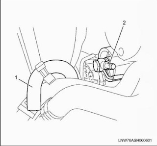
ISUZU IDSS MX2-T Diagnostic Adapter System Support G- IDSS/US-IDSS/E-IDSS (Included DHL Shipping) Precautions when installing or removing the engine Always apply chock blocks to the vehicle wheels. Select an engine hoist that is able to withstand the weight of the engine. Do not get under the engine while it is hoisted. Never put your hands where they can get easily caught. 1. Disconnect the battery cable negative terminal. 2. Drain the engine coolant. 3. Remove the starter. Refer to "Starter Motor"in Section 1E, Engine Electrical. 4. Remove the front exhaust pipe and exhaust brake. Refer to "Exhaust Pipe"and "Exhaust Brake"in Section 1G, Engine Exhaust. 5. Remove the transmission. Refer to "Smoother Transmission Assembly"in Section 5B, Automatic Transmission (Smoother) for details on the Smoother vehicles. Refer to "Transmission Assembly"in Section 5C, Manual Transmission, for details on M/T vehicles. 6. Remove the air intake pipe and hose. Remove the hose on the intercooler side. Remove the pipe from the turbocharger with the hose attached. 7. Remove the air duct and PCV hose. 8. Disconnect the boost sensor connector (1) and harness clip. 9. Disconnect the ECM connector and clip. 04.2024 ISUZU G- IDSS Truck Diagnostic Software Download & Installation
0 notes