
Don't wanna be here? Send us removal request.
Statistics
We looked inside some of the posts by ian--park and here's what we found interesting.
Average Info
Notes Per Post
1
Likes Per Post
1
Reblog Per Post
0
Reply Per Post
0
Time Between Posts
17 days
Number of Posts By Type
Text
2
Last Seen Tumblr Blogs


Fun Fact
Hackers stole 65M passwords from Tumblr in 2013.
Text
Example codes for Embedded Systems
Last time I introduced embedded systems with their actual usage in the real world and two major kinds of devices what consists embedded systems.
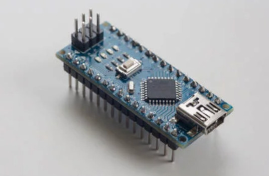
Here is today’s agenda. I’ll introduce two devices, one is a single board computer, Raspberry Pi and the other one is a microcontroller kit, MSP430. With those two devices and peripherals, I’ll demonstrate their various functionally to show what they can do.
Then, why am I choosing those two devices? Raspberry pi is one of the popular single board computer in the world and it is powerful enough to show many functionalities with general purpose operating system. In contrast, microcontroller itself is only a chip, so, I chose MSP430. It is a development kit with many integrated peripherals controlled by microcontroller. With this, it is available to see more visible and dynamic examples with microcontroller.
Here is the simple specification comparison between two devices.
At first, I’ll show simple programming logic MSP430 microcontroller with peripherals. Usually, microcontrollers have no OS, because microcontroller is just a programmable IC chip. So, each manufacturer provides each way to program it. This MSP430 kit is manufactured by Texas instruments and the company supports easy tool to programming it, Code composer studio, an IDE based on eclipse.
Then what kind of programming language is allowed? It also depends on the device, now this MSP430 supports C with libraries to handle its peripherals. So, I wrote sample scripts as C language with supported libraries.
The first example is displaying a word on attached LCD display. Here is the code.
<<Code>>
First declare a method to display word that will be defined late. and initialize resources from the manufacturer to handle peripherals. And use a method to show hello and while loop to hold the logic. Displayword method is pretty simple, it just procedure each character to call a function to show each character into the display.
When you execute this code, the display will show hello on the display.
#include <stdio.h>
#include <msp430.h>
#include <string.h>
#include "myGpio.h"
#include "myClocks.h"
#include "myLcd.h"
void DisplayWord(char word[6]); // Displays words (6 characters or less)
main() {
WDTCTL = WDTPW | WDTHOLD; // Stop WDT
initGPIO(); // Initialize Inputs and Outputs
initClocks(); // Initialize clocks
myLCD_init(); // Initialize LCD
DisplayWord("HELLO"); //Display word in double quotes on LCD
while(1);
}
void DisplayWord(char word[6]) {
unsigned int length;
unsigned int i;
char next_char;
length = strlen(word);
if (length <= 6) {
for (i=0;i<=length-1;i=i+1) {
next_char = word[i];
if (next_char) {
myLCD_showChar(next_char,i+1);
}
}
} else {
myLCD_showChar('E',1);
myLCD_showChar('R',2);
myLCD_showChar('R',3);
myLCD_showChar('O',4);
myLCD_showChar('R',5);
myLCD_showChar(' ',6);
}
}
Let’s try the way of communication, UART. UART means universal asynchronous receiver and transmitter. The purpose of UART is to transmit and receive serial data and this is the main way of communication for microcontrollers.
In UART communication, two UARTs communicate directly with each other. The transmitting UART converts parallel data from a controlling device like a CPU into serial form, transmits it in serial to the receiving UART, which then converts the serial data back into parallel data for the receiving device. Only two wires are needed to transmit data between two UARTs. In UART, data is transmitted by organized packets. In this example, I’ll wire to communicate between Raspberry pi and MSP430. Please check each pinout on official website.
Back to example, so I’m going to send a signal from the microcontroller using press a button. Then, raspberry pi receives the signal from the controller and show the result on a web page. Also, raspberry pi sends a signal to the microcontroller through a web page. Then the controller will display something different on its attached LCD screen with green led light.
Here is the code for microcontroller first.
#include <msp430.h>
#define ENABLE_PINS 0xFFFE // Required to use inputs and outputs
#define UART_CLK_SEL 0x0080 // Specifies accurate clock for UART peripheral
#define BR0_FOR_9600 0x34 // Value required to us 9600 baud
#define BR1_FOR_9600 0x00
#define CLK_MOD 0x4911 // Microcontroller will clean-up clock signal
#define ACLK 0x0100 // Timer_A ACLK source
#define UP 0x0010 // Timer_A UP mode
// Declare
void select_clock_signals(void); // Assigns microcontroller clock signals
void assign_pins_to_uart(void); // P4.2 for TX, P4.3 for RX
void use_9600_baud(void); // UART operates at 9600 bits/sec
void DisplayWord(char word[6]); // Display word in double quotes on LCD
main() {
WDTCTL = WDTPW | WDTHOLD; // Stop Watchdog
PM5CTL0 = ENABLE_PINS; // Enable pins
P1DIR = BIT0; // Make P1.0 an output for red LED
P1OUT = 0x00; // Red LED initially off
select_clock_signals();
assign_pins_to_uart();
use_9600_baud();
initGPIO(); // Initialize Inputs and Outputs
initClocks(); // Initialize clocks
myLCD_init(); // Initialize LCD
UCA0IE = UCRXIE; // Interrupt when TX stop bit complete
PM5CTL0 = ENABLE_PINS; // Enable pins
P9DIR = BIT7; // Green LED is on Port 9, bit 7 (P9.7)
P1DIR = BIT0; // Ensure P1.1 button is an input and P1.0 is an output
P1OUT = BIT1; // P1.1 button needs a pull-up resistor
P1REN = BIT1;
TA0CCR0 = 40000; // 40000 * 25us = 1000000us = 1second
TA0CTL = ACLK + UP; // Set ACLK, UP mode
TA0CCTL0 = CCIE; // Enable interrupt for Timer_0
_BIS_SR(GIE); // Activate interrupts previously enabled
while(1) { // Keep looping forever
while ((BIT1& P1IN) == 0) { // Is P1.1 button pushed?
P9OUT = BIT7; // Turn on the green LED (P9.7)
DisplayWord("CLICK"); // Display "CLICK" on the LCD
UCA0TXBUF = 'a'; // Send the UART message out pin P4.2
}
P9OUT = 0x00; // Turn off the green LED (P9.7)
}
}
// Timer0 interrupt service routine
#pragma vector=TIMER0_A0_VECTOR
__interrupt void Timer0_ISR(void) {
P1OUT = P1OUT ^ BIT0; // Toggle red LED on P1.0
}
// UART interrupt service routine
// This is the ISR for both the TX interrupt and the RX interrupt
#pragma vector=USCI_A0_VECTOR
__interrupt void UART_ISR(void) {
if (UCA0RXBUF) {
P1OUT ^= BIT0; // Turn on the red LED
DisplayWord(" "); // Display empty word on LCD
}
UCA0IFG = UCA0IFG & (~UCRXIFG); // Clear TX complete interrupt flag
}
// Select clock signals
void select_clock_signals(void) {
CSCTL0 = 0xA500; // Password to access clock calibration registers
CSCTL1 = 0x0046; // Specifies frequency of main clock
CSCTL2 = 0x0133; // Assigns additional clock signals
CSCTL3 = 0x0000; // Use clocks at intended frequency, do not slow them down
}
// Used to give UART control of appropriate pins
void assign_pins_to_uart(void) {
P4SEL1 = 0x00; // 0000 0000 (01 assigns P4.2 to UART Transmit)
P4SEL0 = BIT3 | BIT2; // 0000 1100 (01 assigns P4.3 to UART Receive)
}
// Specify UART baud rate
void use_9600_baud(void) {
UCA0CTLW0 = UCSWRST; // Put UART into software reset
UCA0CTLW0 = UCA0CTLW0 | UART_CLK_SEL; // Specifies clock source for UART
UCA0BR0 = BR0_FOR_9600; // Specifies bit rate (baud) of 9600
UCA0BR1 = BR1_FOR_9600;
UCA0MCTLW = CLK_MOD; // Cleans clock signal
UCA0CTLW0 = UCA0CTLW0 & (~UCSWRST); // Takes UART out of software reset
}
// Used to display a word up to 6 chars on the LCD
void DisplayWord(char word[6]) {
unsigned int length; // Used to store length of word
unsigned int i; // Used to step through word, 1 char at a time
char next_char; // The char in word presently displaying
length = strlen(word); // Get length of the desired word
if (length <= 6) { // If 6 or less chars
for (i=0;i<=length-1;i=i+1) { // Loop through each of char
next_char = word[i]; // Get char for the nth slot
if (next_char) { // If char exists (not null)
myLCD_showChar(next_char,i+1); // Show char on LCD
}
}
} else { // If word has more than 6 chars, display error message
myLCD_showChar('E',1);
myLCD_showChar('R',2);
myLCD_showChar('R',3);
myLCD_showChar('O',4);
myLCD_showChar('R',5);
myLCD_showChar(' ',6);
}
}
To use serial communication, define and declare resources first. Then set pins and timer for the red led to blink in idle. While the program is working, if I press the button, it will turn on the green led and display click word on LCD and send a signal to Raspberry pi.
Also, use a custom interrupt for the red led and interrupt when the signal arrived on this controller. If something arrives, turn on the red led and fill the LCD as whitespaces.
The other parts are setting registers to activate UART.
Now let’s see on the Raspberry pi side. I installed django framework to use python code on web server in Raspberry pi.
Here is the main function.
from django.shortcuts import render
from django.http import HttpResponse
import serial
ser = serial.Serial("/dev/ttyAMA0",9600,timeout=10)
def recv(request):
print("start")
print(ser.name)
line = ser.readline()
if len(line) == 0:
print("do something!")
return HttpResponse("No Signal")
else:
print("something happened!")
return HttpResponse("Signal Received")
def send(request):
ser.write(b'a')
return HttpResponse("Signal Sent")
def index(request):
return HttpResponse("Hello World!")
First, I changed raspberry pi’s configuration to use UART communication. So, in the python, unlike the controller, since everything is behind the scenes, it’s much easy to control. Just use a serial library with few parameters and that’s it for UART communication.
And recv is the function to do something when signal is arrived or not. If something arrives while this function is working, it will print something happened on console and show signal arrived on html page. If it is not, print do something and no signal will be shown on the page.
Next, send is the function for send a signal to microcontroller. If a user approach to this page, it will send ‘a’ through the wire. and then show a message. The last one is just index page to show the main page.
And next, I mapped those functions to each URL. So, each function will be executed and show the result when I visit to the mapped location.
Now, you can execute the webserver on the pi and push the script on the controller.
If everything works perfect, you can see hello world in the main page. Then, you can send a message to the controller and see the result on the controller. If the controller received signal, the display will show whitespaces. On the other hand, while the receiving function is working, if no signal found, it will show the No signal, and if it receives signal, then the page will show signal received.
0 notes
Text
The World of Embedded Systems
What is the Embedded System?
Embedded Systems, at a glance, it sounds difficult and something seriously industrious. So, it doesn’t look like familiar thing for a personal user. So am I. Before decide this topic, I had to read articles about this because I was not sure can I deal with it or not.
So, here is the point I decided to introduce this. It used to hot and trendy in tech area for few years ago and its market has been growing and having pretty good forecast and as well as this IoT market, traditional embedded systems already has big market.
Actually, the world of embedded systems is too wide and deep to handle for few blog posts. So, I’ll concentrate to introduce what kinds of things in that world, what can we do with them, and how can we deal with them.

What can we do with it?
Let me see, what is the embedded systems? Embedded system is a category of a computer system which is designed for specific purpose. This is the major difference between the general-purpose computer systems.
Most of embedded systems have combinate structure of an arithmetic processer with memory device and any kinds of input or output peripheral devices. Furthermore, depends on the functionality focus, numerous sub categories exist within.
So, what can we do with embedded systems? The answer is almost everything what we want to do. Embedded systems have many categories, this chart categorise embedded systems as two way, but there are many other theories to categorise embedded systems. But on this post, I am not going to explain those theories. So, I’ll just give some examples based on two simple categories, Big or small. Let’s find embedded systems around us.
Microscopic World!
At first, let’s try to find something small. In many schools, there is a small device attached in a wall on every classroom. I guess that is communicating with main server in somewhere to open or close doors. If my guess is right, it is a kind of embedded system.

In a vehicle, if your car was not manufactured before 1990s, it must be consisted by an embedded system to control the vehicle which is named electronic control unit. It receives data from car parts and control them for stability and better performance.

Additionally, this might unfamiliar example, in oil industry field, companies use devices for pipes to measure amount of oil from inside of pipes and a set of devices to perform it is an example of embedded systems.

Macroscopic World!
Do the examples are too microscopic? That’s true because most of embedded systems are designed to working quietly and working on behind the scenes. Now let’s find them working on the scene.
Nowadays nobody wants to wait in a bank to deposit their money, instead of that, people use ATM machine. Not only a bank, but also in a fast food restaurant, all the long wait queues are replaced by Kiosk machines and those Kiosk machines are a good example of visible embedded systems. Furthermore, a drone, a smart doorbell, GoPro cam - These are all a kind of embedded systems what we could see frequently in the real world.

What can we use for it?
We have seen some examples of embedded systems around us from small things to big things. Each system has different size and different requirements to fulfill their different purpose. Then, what kind of things are used to structure each embedded system? I’ll introduce two common things for embedded systems. Microcontroller and Single board computer.
Microcontroller

First, microcontroller. A microcontroller is a tiny computer circuit chip for automatically controlled products and devices. So, most of tiny embedded devices are working on this. Typically, it contains one or more CPUs along with memory and programmable input and output peripherals.
Each microcontroller is designed to respond each different demand, so it sticks with various technical specification. But the most remarkable point is, microcontrollers are designed for economical way and used widely. In 2012, the average price for 8-bit microcontroller was just 70 cents and worldwide sales of 8-bit microcontrollers were around 4 billion. So only 8-bit microcontrollers were sold nearly 4 billion in a year. And also, 4-bit, 16-bit and 32-bit microcontrollers are popular in market too.
Then, let’s see an example of microcontroller. There is a microcontroller has pretty luxurious specification. 16MHz processor with 16KB Flash memory and 512Byte ram and there is no operating system. Then how can we deal with it?
Each manufacturer provides its own way to handle, and programming languages can be varied depends on devices’ support, like if a device has more limited performance, programming language need to be operated in more low-level. So, assembly and C are popular programming languages for microcontrollers.
Then, is there any device for embedded systems what we can handle like a usual computer?
Single board computer
Let me introduce single board computers. A single-board computer is a complete computer built on a single circuit board, with processor, memory, input and output peripherals. Unlike a microcontroller, single board computers have way more powerful features, so they can be used for diversely. Raspberry Pi and Intel Edison are examples of single board computers.

A single board computer is a small stand-alone computer itself. Therefore, we can install operating system like Linux or Windows and can use any kind of programming languages. So, it’s commonly used in embedded systems which needs more performance, especially IoT stuffs.
What am I going to do?
On this post, I delivered a piece of information about the world of embedded systems. So, on the next post, I would like to demonstrate two types of embedded systems what I introduced here. First, I’ll show using a microcontroller with programming to execute simple task. And then, raspberry pi will be demonstrated with its add-on devices to show more powerful features!
1 note
·
View note