
Hello, I'm from Georgia Institute of Technology, a world-renown university for engineering and technology.
Don't wanna be here? Send us removal request.
Statistics
We looked inside some of the posts by igtengineer and here's what we found interesting.
Average Info
Notes Per Post
0
Likes Per Post
0
Reblog Per Post
0
Reply Per Post
0
Time Between Posts
24 days
Number of Posts By Type
Text
6
Last Seen Tumblr Blogs


Fun Fact
There were a total of 171.5 billion posts on Tumblr in 2019.
Text
TechNote -- np.newaxis replacement
None is an alias for NP.newaxis. It creates an axis with length 1. This can be useful for matrix multiplcation etc.
>>>> import numpy as NP >>>> a = NP.arange(1,5) >>>> print a [1 2 3 4] >>>> print a.shape (4,) >>>> print a[:,None].shape (4, 1) >>>> print a[:,None] [[1] [2] [3] [4]]
0 notes
Text
TechNote -- Tensor Upscale2D
Let’s say that we generate the following tensor: x = torch.randn(2, 2) --> [ [v0, v1] , [v3, v4] ] shape = x.shape And we invoke the following command: y = x.view(shape[0], 1, shape[1]) This results in the following tensor: [ [ [v0, v1] ] , [ [v2, v3] ] ] As you can see, we wrapped an additional dimension. and this “wrap” parameter( which is the “1” following shape[0] ) should follow the dimension that’s wrapped. Now we can duplicate the values into the new wrapping dimension with the following command: y.expand(-1, resize_factor, -1) If the resize_factor is two then the following tensor is returned: [ [ [v0, v1], [v0, v1] ] , [ [v2, v3] , [v2, v3] ] ]
0 notes
Text
Recent Research Focus on Image-to-Image Translation
The Multiscale discriminator structure that is composed of procedurally generated PatchGAN discriminators is used in SPADE to tune the quality of the output. PatchGAN discriminators are in essence ConvNets that reduce everything to the representation of patches. The paper doesn’t mention the presence of a multiscale discriminator, but this structure is used in several projects and can enhance performance. In addition, the output D channels in each individual PatchGAN discriminator is calculated based on the number of
The Base Network structure is the parent of all custom networks in the SPADE project. It provides the methods through which the weights in the networks are initialized. There are initializations through normal distribution, Xavier’s method and so on.
This project also utilizes the ResNet architecture, in which the network has identity connections that skip certain layers. This forces the network to learn the residual rather than the true distribution of the target function, which arguably results in better performance. Modularity is also viable through ResNet by multiplying their numbers to increase depth. The SPADE version of ResNet includes SPADE normalization layers(which can contain primary normalization layers such as instance normalization etc. which are followed by the convolutional layers that create the scaling & addition parameters) and convolution layers. The SPADE ResNet layers are piled together, and within them there are Nearest-Neighbor upsampling layers. The identity connections could be the input itself or a SPADE normalization layer followed by a ReLU layer and ConvNet layer.
SPADE simulates the loss of GAN through BCELoss. Since the two functions are very similiar, and that BCELoss has a negative sign that can convert gradient ascent in standard GAN to gradient descent, which is favored by pytorch. For the generator, all y are set to 0 and V is set to D(G(z)); for the discriminator, all y are set to 1 and V is set to D(x). Below is the original BCELoss function:

Each PatchGAN is composed of a Least-Square GAN, which solves the problem of vanishing gradients that’s prevalent in traditional loss functions. For instance

Which reveals a problem: when the generator and the discriminator distributions do not overlap, there’s no gradient for training. In addition, the entropy loss for GAN doesn’t penalize generated samples that lie on the correct side of the decision boundary but are far from the real distribution, since gradients vanish once they are on the correct side. This discourages the generator to train samples that match the correct data distribution.

Below is the equation of LSGAN:
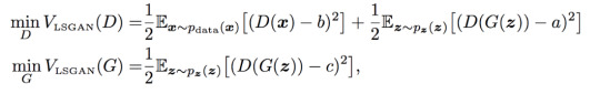
Which solves the problem of satiated gradients by comparing distribution values.
0 notes
Text
OpenGL, GLSL and Optifine -- A Peek into Minecraft’s Shader Facility 1
There is very little information about the creation of Minecraft shaders, and, unlike Minecraft mods, there is only a handful of shader developers(almost forming a oligopoly IMO).
Recently I’ve been digging into Optifine, the all-famous Minecraft plugin that adds advanced graphic control for gamers and developers alike. Its Github documentation, although very beginner-unfriendly as of now, provides enough information for me to get started with Minecraft shaders.
Before talking about Minecraft, we should first focus on OpenGL, since it forms the backbone of Minecraft’s graphics. OpenGL provides an interface for developers to operate on the rendering pipeline, in which a ton of GPU-level programs process small-scale data and form them into a bigger picture. Vertex data, after being specified in CPU-level programs, are fed into Vertex Shaders, which proceed its data to the Geometry Shader to form primitives. These primitives are then rasterized(as opposed to ray tracing) to correspond with the 2D pixels on the computer screen. Each pixel is assigned with a fragment shader that adds color data. In the end, the texture can be stored into a buffer that’s later rendered to the computer screen. Developers have total control over the fragment, geometry and vertex shaders, while the other parts of the pipeline is wrapped by OpenGL.
The shadowmap buffer is what it is: a storage of values that denote how far the closest geometry in a certain spot is from the light source(in this case, the light source can be the sun, the moon or torches).
GBuffer renders the raw data of objects and is separated to different intermediate framebuffers, a technique called deferred shading. Deferred shading allows Optifine to render to different intermediate framebuffers before putting them together. Among these, there is one for the terrain, one for fluid objects( such as water and ice), one for the sky and one for entities. Each GBuffer has its separate data as well: GNormal as object normals, GColor as raw colors, GDepth as the depth buffer used to test occlusion. Occasionally, developers use GBuffer’s lightmap data as well. Note: in development, we often set the values of these data, which are processed by the developers after being extracted from Optifine’s pipeline.
The composite shader is the second last stage of the programmable pipeline. There are about 10 composite shaders that’s rendered in full passes, unlike GBuffer. This is oftentimes the most heavily developed area within the pipeline, since, as full passes come by, developers have access to color data from GBuffer and can add a variety of effects here. Different composites can implement features such as lighting, shadows, reflections, clouds and so on.
The last files, final.vsh and final.fsh, wrap up everything and output the final texture buffer that’s used by the game to render. If this confuses you, remember that each vertex shader shall have a fragment shader that rasterizes vertex based data to and feeds them to pixels for rendering.
During development, I created the following file structure for a basic Optifine shader:
-- GLSLang Folder
------ GLSLang Binary
-- Shader Root Folder
------ gbuffer_terrain.vsh
------ gbuffer_terrain.fsh
------ composite.vsh
------ composite.fsh
------ final.vsh
------ final.fsh
------ Lib Folder
---------- framebuffer.glsl
Which should be self-explanatory after the introduction above. GLSLang a program from the Khronos group that compiles the shader files. Next, before going into the implementation details, I want to emphasize that Optifine requires the developer to re-implement the default stages within the pipeline. This seems to be tricky, but advanced shading is the process in which the developer adds customized and intermediate modifications to what Minecraft already has.
framebuffer.glsl in the Lib folder should provide helper methods, denote subordinate fragment data, modify GBuffer format to increase accuracy and resolution, and provide some useful helper methods.
The gl_FragData[] array contains attributes of a GBuffer texture and stores the information that used to render a GBuffer. Oftentimes, gl_FragData[0] denotes the raw color, gl_FragData[1] denotes the normal, and gl_FragData[2] denotes the depth field. I used several macros to better identify these components:
#define GCOLOR gl_FragData[0] #define GNORMAL gl_FragData[1] #define GDEPTH gl_FragData[2]
Usually, the indices don’t really matter as long as the referencing files follow the defined convention.
Next, we are going to convert the texture resolution to a higher standard:
int RGBA16 = 1 int gcolorFormat = RGBA16
1 is a placeholder that Optifine identifies as the RGBA16 format, which encodes more data into each texture than the default RGBA8 format.
Now we also have several samplers that come from Minecraft’s pre-defined CPU space, as shown below:
uniform sampler2D gcolor; uniform sampler2D gnormal; uniform sampler2D gdepth;
sampler2D is a variable that loads data from a texture unit, which is a position to which a texture object is bound to. Thus, the sub-components of a GBuffer texture can be sampled with:
texture2D(sampler2D sampler, vec2 P)
Which extracts a single pixel from the sampler variable. This allows us to implement the helper functions below, which are used after the GBuffer stage when the subcomponents are ready:
vec3 getAlbedo(vec4 tex_coord){ return texture2D(gcolor, tex_coord.st).rgb; }
vec3 getNormal(vec4 tex_coord){ return texture2D(gnormal, tex_coord.st).rgb; }
getAlbedo returns the current raw color of the pixel, while getNormal returns the normal. Oftentimes, in the composite stage, the normal has to be processed with the Normal Matrix:
normal = normalize(gl_NormalMatrix * normal);
So that the normal vectors are in the camera space, in which most processes take place.
Now let’s go to the first stage of the Optifine pipeline: GBuffer. I’ll only focus on GBuffer_terrain for now:
#version 120 varying vec4 texcoord; varying vec3 tintColor; varying vec3 normal;
void main(){
gl_Position = ftransform(); texcoord = gl_MultiTexCoord0; tintColor = gl_Color.rgb;
normal = normalize(gl_NormalMatrix * gl_Normal);
}
Above is the vertex shader for GBuffer_terrain. The varying keyword both receives and passes a variable. Texcoord is the texture coordinate in UV space; tintColor is the color add-on for an existing texture; normal is self-explanatory. The vertex shader gets information about its position in the world through ftransform() and stores its texture coordinate(through multi-texcoord that accesses information stored in a texture unit, which in this case is in location 0) that’s later interpolated to fragment shaders. In Minecraft this interpolation is quite straightforward since each vertex matches the corner of a textured cube. Tint color is used for tinting effects that does not need much processing for now, so we’ll deal with it in a standard pass.
Next comes the fragment shader for GBuffer_terrain:
#version 120
#include "/lib/framebuffer.glsl"
varying vec4 texcoord; varying vec3 tintColor; varying vec3 normal;
uniform sampler2D texture;
void main(){
vec4 blockColor = texture2D(texture, texcoord.st); blockColor.rgb *= tintColor;
GCOLOR_OUT = blockColor; GNORMAL_OUT = vec4(normal, 1.0);
}
Just a quick reminder about the usability of the GBuffer uniforms in framebuffer.glsl in GBuffer_terrain: they should be referenced in shaders of later stages(such as composite) after being passed to the pipeline, which is exactly what we are doing here.
The sampler texture contains block texture data and is modified by the tintColor(which doesn’t do practical stuff at this stage). Then the terrain texture is passed to GColor’s storage of raw color while the normal is passed to normal storage.
Now that we are done with the GBuffer, we can focus on the composite shader, in which GBuffer textures are processed as unified entities instead of separate G channels:
#version 120 varying vec4 texcoord; #include "/lib/framebuffer.glsl"
uniform int worldTime; uniform vec3 sunPosition; uniform vec3 moonPosition;
varying lightPosition;
void main(){
if(worldTime < night_start || worldTime > night_end){ lightPosition = normalize(sunPosition); }else{ lightPosition = normalize(moonPosition); }
}
In the next update, I’m going to talk about the processing of light within the composite shader.
0 notes
Text
A Theoretical Approach to Quadcopters -- 1
Since I love controllable aerial vehicles(like a lot of other people) and beautiful natural scenes at the same time, there’s nothing better than making a drone that can easily rise to the sky and capture photos. In this post, I’m going to report what I found during my research for the construction of Quadcopters and summarize everything that’s needed to build one. In the end of this series, I plan to construct a Quadcopter and test it in the wilderness(hopefully).
Quadcopters, just as what its name suggests, often consists of a frame that contains the electronics, four motors(and propellers) that provide thrust and movement, four Electronic Speed Controllers(aka ESCs) that correspond to each motor, several battery cells, a transmitter that receives commands from the ground, a controller for the ground pilot, and a central board that integrates the other components to create a complete system.
Now, let’s dissect these components one by one so that, in the end of this article, I myself will have a clear idea of my own research :)
Motors and Propellers
Motors are the primary components that drive the drone’s movements. Oftentimes, motors used for Quadcopters have the following properties:
Has a KV, also known as RPM/v, of about 1000.
Has a diameter and length of less than 40mm.
Requires 3 ~ 5S LIPO batteries.
Has a max thrust of about 1000G(should be two times the weight)
Is compatible with 15 ~ 20A ESCs
For the propellers, they can be about 10 ~ 30cm long, depending on the size of the Quadcopter. Oftentimes, if the copter is small and built for race, the pitch shall be small so that more torques are generated within a constant distance to gain acceleration. On the other hand, the pitch should be relatively long to support bulky equipments such as cameras and additional batteries(often mounted on H shaped copters).

After mounting the propellers on the motors, they shall be arranged so that the motors on the upper-left side and lower-right side rotates on the clockwise direction, while the others rotate on an anti-clockwise direction. Moving horizontally to the left would require the controller to decrease the speed of motors on the left side, for instance. Rotating on the yaw direction requires a single motor to decrease its speed. For instance, decreasing the speed of the upper or(exclusive! ) lower left motor turns the copter to the left in the yaw direction. Also note that everything in this pose will be on a four-motor frame :)
Electronic Speed Controller
Each ESC has three sets of wires: one for the motor, one for the batteries, and the last one for the control board. The motor set often has three identical wires, which are simple enough to save the description. The control set is the most complicated, with a PWM wire for modulating the speed of the motor with analog input signals, a VCC wire that connects to Arduino’s 5V port, and a GND wire that connects to Arduino’s ground. The last set of VCC and GND wires connect to the external power source. Oftentimes we stick one ESC to each arm within the frame. In addition, it is recommended to use a 15A ESC for each motor.

Transmitter and Controller
The controller, the fancy kind that every kind should have, has four pre-defined channels of control and two additional channels for custom maneuvers. For Quadcopters we’ll probably only focus on the throttle channel but the others are: Ailerons, Rudder and Elevator. The throttle channel should also have a trim channel that further restricts from its re-defined interval. In addition, the controller might have on-board RAMs used to save the configuration. The transmitter should be a module that receives signal from a pre-defined controller. I’ll talk a lot more about how they work and how these components are put together in the incoming posts.
0 notes
Text
L298N Set-up with Arduino Hardware --- Robotics
Completed the set-up of a L298N chip and its interface with an Arduino Uno board.
The layout is quite simple: ENA and ENB are both connected to two analog ports in Arduino. These ports receive Pulse-Width Modulated signal from the board and adjusts the electrical signals in OUT1 ~ 4 accordingly. If I’m ever going to control them with a joystick or potentiometer, I’ll have to map the input range of these additional peripherals to the standard of these PWM ports. By placing Arduino in between the potentiometer, connected to on-board ground and 5V output, I should be able to modulate the speed of the motors.
Now that the PWM ports are out of the way, I continued to work on ports that control the direction of motors.
Basically, each motor is assigned two IN ports whose pattern of currents controls the direction: IN1 ~ HIGH and IN2 ~ LOW can be forward while IN1 ~ LOW and IN2 ~ HIGH can be backward. The principle behind this is the H-bridge pattern within L298N: the upper portion of the “I” in the left side of “H” and the lower portion of the “I” on the right side of “H”, connected in the middle by the “-” portion of “H” create a pattern with, let’s say, a low voltage on the left side and a high voltage on the right(depending on the direction of the current). Reversing this pattern can cause the voltage to be high on the right side and low on the left side. This allows L298N to control the motor’s direction.
That’s where Arduino fits in, since it allows the board to output a certain pattern of electrical signals, controlled by the programmer. Thus, I used jump wires to connect four Arduino pins with the IN ports, from IN1 to IN4. I’m unable to find a way to force Uno to receive commands from the keyboard without modifying it. But a potential way to do so is to utilize HID libraries on Github to rewrite the board and forcefully insert a renewed binary(which, essentially, forces Uno to behave like Leopard and can possibly weak havoc). Thus, I’ll use a Bluetooth module instead and connect it to a custom virtual joystick on my cell phone.

Then comes the motors, the most essential part of this project. I plan to use at least two 6~9V TT DC motors for a functioning robot. In addition, most industry-level motors are 12V+, which means that external power source is necessary. Recall that Arduino Uno only supports a voltage of 5V-, and each pin can only support a maximum of 50MA with a total limit of 200MA for all pins. So what we often do is to attach a battery box’s power wire to the VCC terminal in L298N, while the ground wire connects to the GND terminal along with another wire that’s connected to Arduino’s GND pin.

Then comes the code. To summarize, I set every connected pin’s mode to OUTPUT, including IN1 ~ 4 and ENA/B, and then created a function that alters the pins’ values according to the intended direction of movement. I will probably publish the code once the whole project is done.
The next steps:
Connect the Bluetooth module to the circuit
Finish the custom app(aka the virtual joystick)
Finish the vessel’s main body with cardboard materials
Add support for app and Bluetooth in the code
Ground trial!
0 notes