
ll University of Hertfordshire, UK ll Environment Game Artist || 23 ||
Don't wanna be here? Send us removal request.
Statistics
We looked inside some of the posts by jian-wei-24 and here's what we found interesting.
Average Info
Notes Per Post
2
Likes Per Post
2
Reblog Per Post
0
Reply Per Post
0
Time Between Posts
4 days
Number of Posts By Type
Text
17
Last Seen Tumblr Blogs


Fun Fact
Tumblr was created by web developers David Karp and Marco Arment.
Text
Final Masters Project: Forefront (Production Workflow)

Figure 1: Dmitry Rusakovich's Tavern on the road. (Rusakovich, 2025)
Dmitry’s journey began with simple tutorials and grew into structured learning through a course. This reflects the value of starting with small steps and then seeking guidance when ready. In my own work on a colonial Malaya environment I also combine self study with targeted learning resources. I watch free and purchased tutorials on specific tools such as Blender, Substance 3D Designer or Unreal Engine and then apply those lessons directly to assets like kopitiam furniture or period tiling.


Figure 2: Dmitry's Reference board. (Levine, G and Rusakovich, D., 2025)[Left] Figure 3: My Reference board. [Right]
The practice of gathering rich references before modeling is central to both Dmitry’s tavern project and my own scene. He collected images for building shape and detail then revised the blockout to match the concept. I similarly research historical architecture through real life images and google maps, and Peranakan design motifs. I assemble a reference board with photos of actual shophouse facades, furniture, tile patterns and interior fixtures. Documenting how each reference influences my blockout and early simple models helps demonstrate a thoughtful approach to authenticity and creative direction.


Figure 4: Dmitry's modular wood and wall piece. (Levine, G and Rusakovich, D., 2025) [Left] Figure 5: My Modular pieces. [Right]
Modularity and logical division of assets featured in Dmitry’s work. He separated building modules and treated unique elements with care. In my environment I adopt the same idea. I design core modules such as wall segments or roof beams that reflect colonial and Peranakan styles and then craft unique props such as period furniture or decorative elements.

Figure 4: Dmitry's roof creation.
The roof creation stands out as a brilliant solution because it uses Unreal Engine’s Nanite to turn a simple base mesh into richly detailed geometry through displacement mapping. First the basic roof mesh is remeshed with enough triangles to capture the height map detail. Then a Texture 2D Map is applied as displacement so the tiles gain real geometry rather than relying on simple normal maps. This method produces fine tile shapes and edge variation without the need to sculpt every detail by hand. The subsequent use of simplify tools to remove softness and manual cleanup in Blender ensures the mesh remains both accurate and efficient. Adding a skirt of tiles along the edges further improves realism and structural coherence. This workflow cleverly combines procedural steps with manual refinement to achieve impressive detail while keeping performance in check, showcasing forward thinking in environment art. I plan to utilise this tip when I reach the part where I create the roof of the kopitiam (Coffee shop) shophouse.
Composition and lighting are essential in guiding the viewer’s focus. Dmitry positions the tavern off center and uses leading lines and framing elements to draw the eye. In my scene I will simplify neighbouring buildings so they have fewer details and naturally direct attention to the central kopitiam entrance. I will frame that entrance with period street lamps and foliage if time allows. I plan to use dynamic lighting in Unreal Engine with global illumination to create an evening mood. Only the kopitiam will be illuminated while adjacent buildings remain dark with their lights off. This deliberate use of light helps steer the viewer’s gaze toward the heart of the scene.
Finally Dmitry reflects on the importance of feedback and persistence when outcomes were uncertain. I also seek critique from peers and professionals to refine my historical environment. In my blogs I share how I responded to feedback on architectural accuracy or texture realism. By iterating based on input led to clearer and direct storytelling in my scene. Hence with an open mindset and willingness to revise are key to professional growth and to producing work that resonates as a cultural artifact.
References
Levine, G and Rusakovich, D. (2025) Storytelling in a 3D Scene: Creating an Old Tavern with ZBrush & UE5. [online] 80.LV. Available at: https://80.lv/articles/storytelling-in-a-3d-scene-creating-an-old-tavern-with-zbrush-ue5. [Accessed: 22 June 2025]
Rusakovich, D. (2025) Tavern on the road. [Online] ArtStation. Available at: https://www.artstation.com/artwork/lGEQ5o. [Accessed: 22 June 2025]
0 notes
Text
Final Masters Project: Modelling Progress (Cupboard).

Figure 1: Cupboard references.
Several references were studied to inform the design of the cupboard, drawing inspiration from Peranakan culture regardless of regional origin, alongside traditional Chinese-style cupboards. To enhance authenticity, elements from both were blended thoughtfully. However, certain traditional building techniques were deliberately set aside in favor of more Western-style features. For example, the classic wooden pivot pins used for cabinet doors were replaced with internal Western hinges, and excessive wood carvings were avoided. These design choices reflect the narrative context of the project, where the cupboard belongs to a moderately wealthy family, capturing a subtle cultural intersection and practical adaptation in colonial-era Malaya.

Figure 2: Base shape of the cabinet.
Using mirror modifier to speed up the modelling work, the base shape was create based on real world estimation and references. Several topology techniques was utilised to limit the edges from running along the model and creating unnecessary extra polygons.
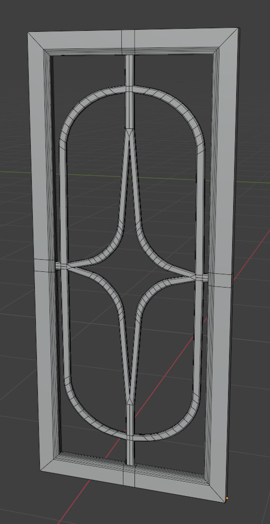
Figure 3: Cabinet's main doors.
The main door was created using vertex modelling by extruding individual vertices to define the desired shape and flow. Once one edge flow of the design was complete, it was duplicated and bridged with its counterpart to form a full face. The modelling focused on crafting just one corner of the ornate inner frame first. Afterward, the object's origin was moved to the centre, and a mirror modifier was applied to replicate the design across all four corners, ensuring symmetry and efficiency. To give the inner outline a classic vintage touch, a picture frame–like bevel was applied. Finally, a large flat plane was positioned within the frame to represent the glass panel.


Figure 4: Connection into the door frame. [Left] Figure 5: Keyhole on one of the frame. [Middle] Figure 6: Pull rings for the cabinet doors. [Right]
The inner ornate design was connected into the main frame for better texturing appearance later.
As this cabinet would store goods to be sold, a key-lock mechanism is required so no one unauthorised were to open the cabinet to steal the goods or thinker around with the goods.
A bat shape pull ring was implement as a visual cue of telling the viewer how to open these cabinet doors. The bat shape was used as it is one of the lucky shape in Chinese culture context.
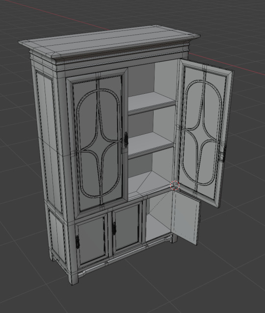
Figure 7: Final look of the cabinet.
Referring to figure 6, the cabinet is completed. All edges were bevelled slightly to prevent a sharp corner look.
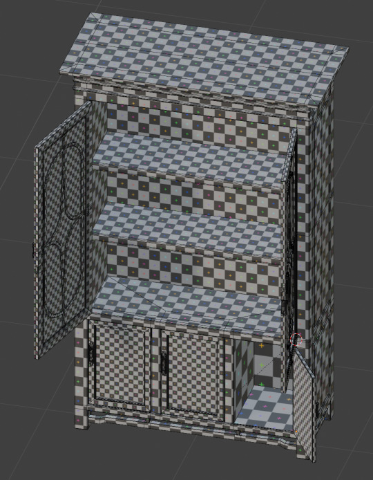

Figure 8-9: Cabinet's texel density in orthographic view.
The UV layout of the main cupboard was layout over 4K resolution checkers as I was unable to fit all the UV parts into the 2K resolution checker grid.

Figure 10: Lower Cabinet door uses the same UV space.
While each upper cabinet has its own UVs and the three cabinet below shares the same UVs.
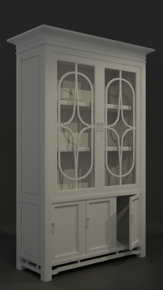

Figure 11: Final design rendered in Blender. [Left] Figure 12: Concept art of the cupboard. [Right]
Significant adjustments were necessary to maintain authenticity and historical accuracy. The original concept art depicted a cabinet that was overly long in length, which would be structurally impractical as it could potentially collapse under excessive weight without central support. Additionally, the inclusion of three layers of tall cabinet storage where the middle layer is big enough for multiple layers was found to be unrealistic after reviewing various reference materials (refer to Figure 1), as it would make the cabinet excessively tall and difficult to access efficiently in daily use. Lastly, the sliding glass door mechanism appears to be a more modern invention and was not commonly seen in the intended historical time period of the environment.
0 notes
Text
Final Masters Project: Forefront (Design Workflow)
Figure 1: Jake Lipelt's Wizard Tower. (Lipelt, 2025)
Reading the breakdown of the Wizard Tower project by Mr. Jake Lipelta, fellow material artist, offered an inspiring perspective on combining personal research, artistic direction, and procedural workflows. Their decision to focus on historical sources such as the works of Frank Frazetta and Jim Henson rather than recent popular media reflects a deeper commitment to originality and authenticity. This mirrors my own approach in developing a 3D environment based on colonial Malaya, where I draw heavily from cultural history, archival references, and traditional design rather than modern reinterpretations.
Like the artist, I prioritise building a strong narrative foundation through research before modeling. While they built their composition around magical fantasy themes, my environment tells the story of a unique cultural blend between Peranakan Chinese heritage and colonial British influence. Their use of personal sculpting and modified assets from museum collections is similar to how I study and adapt traditional furniture design to reflect a historically accurate and emotionally grounded setting.
youtube
Video 1: Demonstration of procedural texturing. (80lv, 2025)
Their procedural texturing method using controlled masks and layered noise to simulate wear and environmental storytelling also resonates with my own techniques. I would apply similar principles when weathering exterior walls, slightly damage furniture, and ensuring the visual logic of material flow aligns with the real-world function and decay of the objects. Their workflow in Substance 3D Designer and focus on the height map before detailing other channels has encouraged me to rethink how I construct my surface variation and texture logic. This article also further my interest in utilising Substance 3D Designer for my texturing process later down the production line.
Another key takeaway was the importance of relying on meaningful references and choosing educational resources that prioritise understanding over shortcuts. As a developing artist, I deeply resonate with the idea of avoiding surface-level, result-driven tutorials and instead seeking material that explains the underlying principles of the tools. This approach has significantly shaped how I learn and apply techniques, particularly within Substance tools and Unreal Engine. One of the steps I have already taken to grow in this direction is by sharing my work publicly to invite feedback from experienced professionals. Their insights have been invaluable in helping me identify areas for growth and refine my workflow with clarity and purpose.
Reference
Lipelt. J. (2025) Wizard Tower. [online] ArtStation. Available at: https://www.artstation.com/artwork/Gvdyd4. [Accessed: 19 June 2025].
Rutherford, A. and Lipelt. J. (2025) How To Texture A Large-Scale Scene Using The Layer System In Unreal Engine. [online]. 80.LV. Available at: https://80.lv/articles/how-to-texture-a-large-scale-scene-using-the-layer-system-in-unreal-engine. [Accessed: 19 June 2025].
80lv. (2025). Noise. [online] YouTube. Available at: https://www.youtube.com/watch?v=i0lgT-aC2rs. [Accessed: 19 June 2025].
0 notes
Text
Final Masters Project: Latest Progress Feedbacks
After receiving valuable feedback on my production practices from the Polycount community, I took some time to revise and improve the assets accordingly.
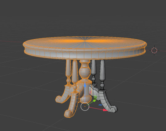
Figure 1: Table Asset.
To optimise UV space and reduce unnecessary texture usage, I separated and duplicated the back two legs of the table from the main model. This change allows for more UV space to be allocated to parts of the model that are actually visible to the viewer. Since players will mostly be looking at the table from the front or side at a time, the back legs' texture won't be noticeable to be similar with the front.
Another reason would be that the audience viewing the environment would not be able to crouch down to notice the similarity of textures or the bottom part of the table. The reason being is that crouching interactive feature is not planned.
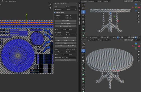
Figure 2: Table UV Layout.
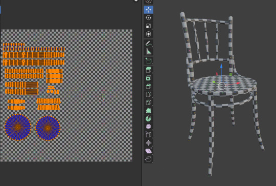
Figure 3: Chair UV Layout.
The top surface and rim of the table now have higher resolution to ensure texture clarity where it matters most. Viewers will naturally focus on the table’s surface first, especially in a dark, nighttime environment where lighting is limited. In contrast, areas underneath the table have lower texel density, as they are less likely to be seen.

Figure 4: Texel Density between the chair and table.
I also made sure that the texel density of the table and chair match closely, maintaining visual consistency between the assets. Since the UV layout for the chair had some extra space on the right, I’ve planned for a second chair model to share the same UV space. This approach helps keep texture use efficient while supporting asset reuse.
I am truly grateful to Noren from the Polycount community for providing such valuable and thoughtful feedback. For a long time, I hesitated to share my work publicly because I feared receiving criticism that might discourage me or affect my motivation. However, I have come to understand that staying within my comfort zone only limits my growth and keeps me from reaching my potential. Taking this step has been challenging, but I am glad I made the decision to put my work out there. Noren's feedback has already deepened my understanding of the technical side of this field and reminded me how constructive critique can lead to real improvement.
0 notes
Text
Final Masters Project: Forefront (Decal Mesh)

Figure 1: Decal trimsheet + decal mesh workflow. (Hu, 2025)
I was aware of decals usage in Unreal Engine to create quick and optimised details to assets and environment. However, I was not aware about the usage of Decal mesh until I came across Jolyn Hu's ELEGY OF THE CLAN: Ghost Of Tsushima Inspired Art on ArtStation. She successfully projected highly detailed normal and material maps onto low-poly mesh models, effectively creating the illusion of complex surface detail without sacrificing performance. Additionally, her use of edge decals blended seamlessly with the trimsheet, demonstrating a great understanding of texture integration. It was truly a remarkable execution of optimisation and visual quality.
youtube
Video 1: EVERYTHING You Need To Get Started Texturing Large Game Assets. (Tiedie, 2023)
This method was also briefly discuss in Tiedie's guide to texturing game assets where he talks about decal mesh.
I did some research about this interesting way to optimise game assets. Essentially, decal meshes, or mesh decals, are an effective technique for adding detail without excessive geometry from sculpting. Instead of embedding detail directly into the base mesh or relying solely on shader effects, decal meshes allow artists to overlay small textured meshes onto surfaces. This approach is particularly useful for adding items like dirt, stickers, or edge wear, which would otherwise require complex geometry or large textures. Since Mesh decals are imported as decals for static meshes, they can benefit from instancing, geometry batching, and selective optimisation.
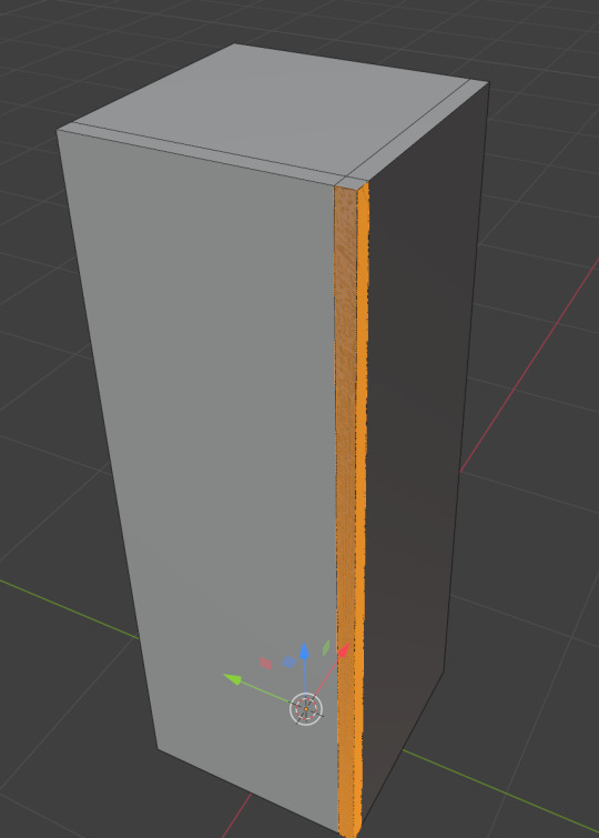

Figure 2: Subdividing selected corner. [Left] Figure 3: Sculpted corner. [Right]
After watching several YouTube tutorials, I consolidated the knowledge I had gathered and conducted a brief test to better understand the workflow. For this experiment, I duplicated and separated a corner section of an existing model, then performed a quick sculpting pass in Blender. The process was kept minimal since it was intended only as a testing exercise.

Figure 4: Final appearance.
Following the sculpting process, I exported both the low poly and high poly versions of the corner mesh into Substance Painter. Using the baking workflow, the detailed information from the high poly version was successfully projected onto the low poly model. Once the baked textures were exported, I imported the low poly mesh, which consists of only three polygons, into Unreal Engine. A decal material was applied using only the normal map to achieve the intended visual effect, as shown in Figure 4.
This decal mesh exercise and research helped me grasp how to efficiently add high-detail visuals to game assets without burdening the game performance. Overall, this hands-on approach has boosted my confidence in creating stunning game environments by using this optimising technique effectively.
References
Abdellatif, T. (2022) Creating Immersive Game Worlds with Unreal Engine. [online] The Rookies. Available at: https://discover.therookies.co/2022/01/26/creating-immersive-game-worlds-with-unreal-engine/?utm_source=chatgpt.com. [Accessed: 15 June 2025].
FastTrack Tutorials. (2021) Creating Edge Damages for 3D Assets using Decals. [online] YouTube. Available at: https://youtu.be/5-pDKn1jVgk?si=EJp88lF50ceBpNXN. [Accessed: 15 June 2025].
Haggerty, M. (2019) [Tutorial] Enhancing your Scenes with Natural Looking Mesh Decals and Skirts. [online] Medium. Available at: https://medium.com/gametextures/tutorial-enhancing-your-scenes-with-natural-looking-mesh-decals-and-skirts-bc5afe389689. [Accessed: 15 June 2025].
Hu, J. (2025). ELEGY OF THE CLAN: Ghost Of Tsushima Inspired Art. [online] ArtStation. Available at: https://www.artstation.com/artwork/1NkrRX. [Accessed: 15 June 2025].
The DiNusty Empire. (2020). Setting Up Mesh Decals. [online] YouTube. Available at: https://www.youtube.com/watch?v=Aihha0sAOJI&t=282s. [Accessed: 15 June 2025].
Tiedie. (2023). EVERYTHING You Need To Get Started Texturing Large Game Assets. [online] YouTube. Available at: https://youtu.be/QcqJckp_q3M. [Accessed: 15 June 2025].
0 notes
Text
Final Masters Project: Modelling Progress (Kopitiam Chair).

Figure 1: Kopitiam chair references.
Several references were analyzed to identify the common design characteristics of traditional kopitiam (coffee shop) chairs, as subtle variations exist between different models. Through visual analysis, key consistent features were observed: a circular support ring beneath the seat, diagonal side supports connecting the backrest and seat, and three vertical cylindrical bars forming the backrest structure. These elements were noted as essential in accurately modelling the chair.

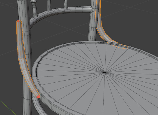
Figure 2-3: Usage of curves.
The chair’s leg flow were initially shaped using vertices, which were then converted into curves to facilitate the generation of a clean cylindrical shell using its settings. This method allowed for better control over the form and ensured consistent thickness along the curve. The lower portion of each leg was tapered to create a more realistic and refined silhouette, reflecting how chair legs tend to narrow near the ground.
The same curve-based approach was applied to model the circular support ring beneath the seat and the diagonal side supports connecting the backrest to the seat.
To maintain symmetry and optimise workflow efficiency, a Mirror Modifier was applied to replicate one half of the chair's legs, reducing modelling time while ensuring structural consistency.
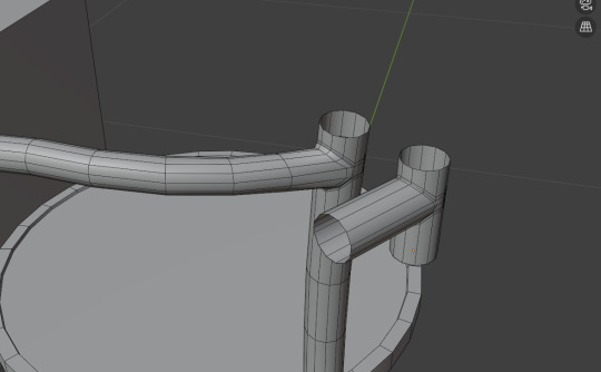
Figure 4: Joining of backrest to one of the chair support.
I initially had difficulty merging the horizontal backrest support with the long chair legs into a single mesh while preserving clean topology for correct ambient occlusion baking. After several experiments, I modelled this section by combining two cylinders with matching vertex counts then rotated one cylinder to form a “T” intersection and then joined them by bridging edges and merging vertices, creating a cohesive tube-like junction. I added supporting edge loops around this connection to maintain a smooth flow of quads and prevent shading artifacts. This approach ensured that the combined geometry would bake ambient occlusion correctly and allow for clear edge detail during the texturing stage.

Figure 5: Chair model and brief human model.
The chair model is displayed alongside a reference brief figure representing an average adult height to verify correct scale and ergonomics. The first edge loop is the waist, then the shoulder and lastly the head at the top. This comparison ensures that seat height, backrest dimensions, and overall proportions align with realistic human use. The chair is also model based on online dimensions of the reference chair.
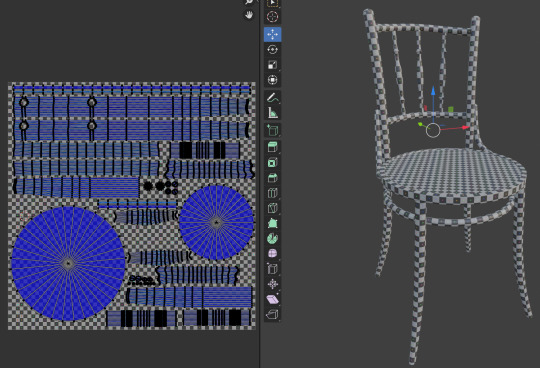
Figure 6: Chair UV unwrapped.
Similar to the table, increased the UV space for areas most likely to be seen so the textures stay sharp, while keeping the texel density even across the entire model to avoid mismatched detail.
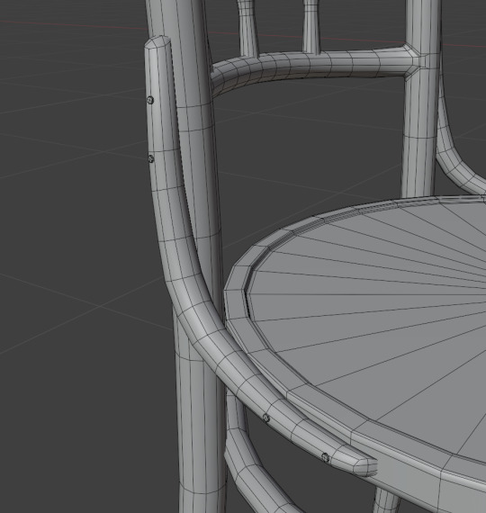
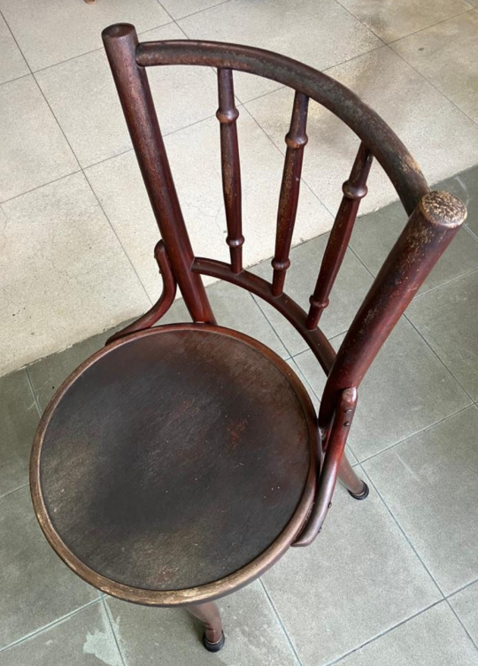
Figure 7: Nails. [Left] Figure 8: Real World Refence. [Right]
Several small cylindrical nail models were added along the sides of the chair to visually indicate how the wooden components are secured together, based on real-world picture evidence.

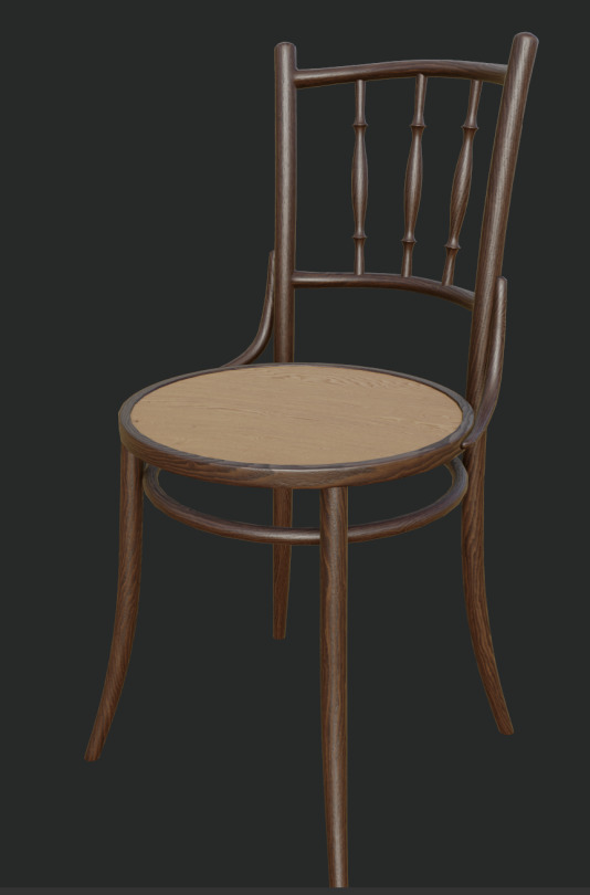
Figure 9: Middle and high poly model. [Left] Figure 10: Temporary texturing test. [Right]
Two levels of poly model was created for baking texture purposes where high poly details are baked onto the lower poly model. Figure 8 shows a temporary texture test applied to the model. This lets me check that the UVs and basic material settings work correctly such as the flow of wood grains.
0 notes
Text
Final Masters Project: Modelling Progress (Marble-top kopitiam table).


Figure 1: Outline Sketched. [Left] Figure 2: Vertex Modelling. [Right]
After researching and examining various table references, I decided to adopt a more understated design with no wood carving. This choice reflects the context of the kopitiam's owner, who is moderately wealthy. It is likely that most of the owner's budget would have been allocated to more prominent and visible elements, such as the exterior façade and the decorative wall divider at the rear of the room, rather than smaller furnishings like the tables.
Using vertex modelling technique on the roughly sketched outline of the table's leg design to create the shape of the table's leg.

Figure 3: Brief table design.
To efficiently visualise and construct the table, I used an empty object as a reference for one of the full leg supports. By applying an Array Modifier and setting the offset type to 'Object Offset' using the empty, I was able to duplicate the leg support around the remaining three sides by rotating the empty to achieve the desired positioning. This non-destructive approach not only streamlined the modelling process but also allowed for rapid visualisation and adjustments to the leg placement during the early design phase.

Figure 4: Table top adjustment.

Figure 5: Table leg redesign.
Based on feedback received from Mr. Neil and Mr. Eden during the review of the WIP screenshot, several adjustments were made to enhance the table model. They noted that the table top appeared too blocky despite the use of a Shade Smooth modifier. To address this, the table top geometry was further subdivided to create a smoother and more natural circular form. Additionally, Mr. Eden advised revisiting the table's topology to remove unnecessary edge loops and to soften the sharpness of the leg profile. In response and referring to figure 5 as an example, the several parts of the table's geometry was refined with cleaner edge flow and a more polished silhouette, enhancing both its realism and visual appeal.


Figure 6: Final Appearance. [Left] Figure 7: Underneath Table Reference. [Right]
The table leg support beams, along with the central support core beneath the tabletop, were modeled using simple edge loop insertions, extrusion, and beveling techniques applied to a base cylinder mesh. Following further research into historical references, it became apparent that additional horizontal wooden support beams were typically present beneath similar tables to reinforce the tabletop structure. As a result, these elements were incorporated into the design to enhance structural accuracy, as shown in Figure 7.

Figure 8: UV Unwrap Table.
Upon modelling completion, the table model was UV unwrapped with careful consideration to texel density. UV islands occupying the most visible or surface-heavy areas were scaled slightly larger to maintain texture clarity, while ensuring the overall texel density remained consistent and proportional.

Figure 9: Middle poly and high poly.
The tabletop was not further subdivided, as it already featured sufficient edge density to appear smooth, particularly for a mid-poly asset. A corresponding high-poly version was created specifically for baking purposes, allowing finer surface details to be transferred onto the mid-poly model.
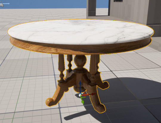
Figure 10: Table imported into UE5 and textured.
UV islands were strategically arranged and rotated to follow the natural wood grain direction, in alignment with real-life references. This is demonstrated in Figure 10, where a temporary baked texture has been applied to preview the wood flow and material coherence.
A lot of time was utilised in creating and re-adjusting this specific model. However, I have familiarised myself with this workflow process and have been able to create models faster compared to before.
0 notes
Text
Final Masters Project: Latest Progress Feedbacks

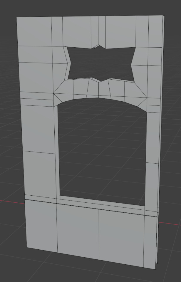
Figure 1: Window Wall before feedback. [Left] Figure 2: Window Wall after feedback. [Right]
During my weekly tutorial with Mr Wayne, I seek advice on the topology of the window wall as I was unsure about the edges all ending in a single vertex.
Following Mr Wayne’s advice, I added edge loops to convert triangles into quads. The new edges run along elongated faces to prevent texture stretching and uneven resolution. Although this approach slightly increases the polygon count, it eliminates potential errors. I also avoided overloading any single vertex with too many connections because, as Mr Wayne noted, some software may struggle with complex vertex configurations and produce unwanted artifacts.
He also gave advice on 3D exporting file format on which one is better. He informed that newer Alembic and USD are better in carrying all the necessary details across software.
Mr Wayne also recommended importing each completed model into Unreal Engine for an early functionality check before moving on to the next asset. This approach assist myself to catch and correct minor issues immediately, so I would avoid having to return to the modelling software later that would interrupt my workflow.

Figure 3: Additional edges to the window wall.
During Friday’s class, Mr Eden and Mr Neil both agreed that Figure 1 was preferable. They explained that on a flat surface it is not essential to maintain quads everywhere, since textures will remain accurate when the geometry does not protrude. Mr Neil suggested adding extra edges to the top left and right corners of the main window area, as shown in Figure 3. This adjustment corrects the irregular quad shape visible in Figure 2.

Figure 4: Additional edges to the main window.
Both Mr Eden and Mr Neil advised adding more edge loops along the upper section of the main window to achieve a smoother curve. They also recommended using a more generous polygon distribution and avoiding overly large faces, which can make the geometry look blocky.
I have learned a wealth of valuable insights relevant to my award field from these three exceptionally knowledgeable professionals. Their diverse perspectives and practical advice have already begun to shape my modelling approach and project planning. I look forward to sharing my work with them and receiving further guidance on technique and presentation. Their ongoing mentorship will deepen my understanding and sharpen my skills, helping me grow into a more confident and capable practitioner in this discipline.
0 notes
Text
Final Masters Project: Modelling Progress (Window Wall & Doorway Wall)

Figure 1: Very simple human model.
A 3D human dimension reference model standing 1.65 metres tall was created to guide the scale of all new assets. The inward-shrinking midpoint marks the human waist, the upper edge represents the shoulders and a small cube extrusion on top indicates the head. This reference helps confirm that all models fit an average person’s proportions for the period.
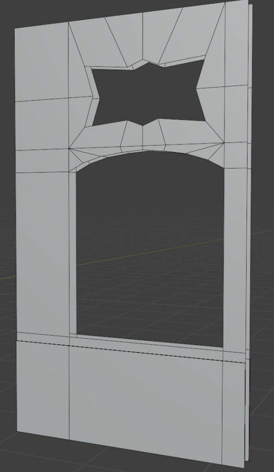
Figure 2: Window wall model.
The lower wall section was extruded to allow for Peranakan tile textures. A larger opening was cut for the main window and its grill, while a smaller, bat-shaped hole above serves as ventilation.
I decided not the extrude out the windows and ventilation holes directly from the main wall to reduce the polycount as there will no longer need to have extra edge loops on the window wall model to ensure that all edges will form a quad. Which might produce a lot of unnecessary quads throughout the window wall model.

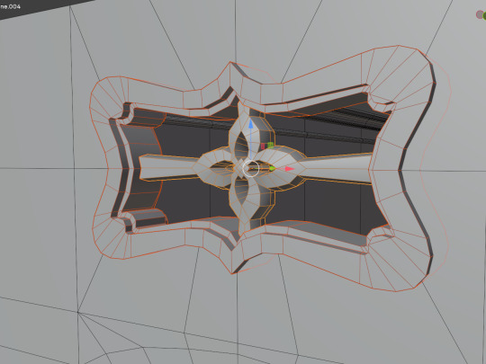
Figure 3: Main window and its grill. [Left] Figure 4: Window wall's ventilation. [Right]
To keep polygon counts low, I chose not to extrude the window and ventilation shapes directly from the main window wall. Instead the window frame was modelled separately with outward-extruded edges that support clean quad topology.
The window grill consists of a single thin cylinder that is arrayed across the opening to show how the finished assembly will look. Once modelling is complete only one grill piece will be exported to Unreal Engine and then duplicated in the scene. This approach frees up more texture space for other elements and lets me rotate each bar slightly to give each one a unique appearance.

Figure 5: Main Window's UV Unwrapped.
Additional edges were added within the frame to guide realistic wood grain alignment during UV unwrapping, as seen in figure 5.
The ventilation grille shown in figure 4 was created by tracing concept art from Anushka Ghosh (2025) using vertex-by-vertex modelling. Its outline was extruded to add depth and inner vertices were adjusted to soften sharp corners and introduce smooth, decorative shapes.
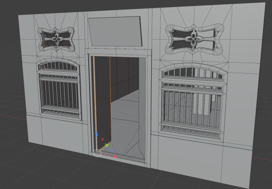
Figure 6: Doorway Wall and its doorway wooden plaque model.
The doorway wall is still a temporary blockout model because I spent too much time perfecting the exterior walls instead of focusing on interior furniture. Progress on this section will pause so that I can prioritise completing the furniture models.
0 notes
Text
Final Masters Project: Modelling Progress (Interior Wall and Floor).

Figure 1: Interior wall and floor.

Figure 2: Dimension estimation based on real life images.
During preproduction I reviewed academic papers on shophouses and examined online photographs of historic Malaya Shophouse examples (Some examples can be seen in figure 2). From these sources I estimated the dimensions of the entrance room that visitors see when they enter the kopitiam shophouse. Finding accurate blueprints proved difficult because many of these buildings have been altered for modern use and no longer reflect their original form. In addition most reliable reference books and archival sources with precise measurements are available only in Malaysia and can be prohibitively expensive to obtain. Once I return home I intend to acquire these publications and refer to their data to make any much needed corrections to my models.

Figure 3: Duplicated modular pieces.
The entrance room is estimated at 7 metres wide, 9 metres long and 4 metres high. Walls and floors were modelled as modular units that can be duplicated six times to cover this area accurately.

Figure 4: Evidence of tiled walls for Kopitiam.
The lower portion of the walls was extruded slightly to facilitate the application of the kopitiam’s iconic tiled wall texture.
Also while researching for image reference, I realised that there were existence of crown moulding for the interior. Based on figure 2 and some quick research, The type of crown moulding utilised that seems rather close to the image references would be Classical Colonial.


Figure 5: Vertex modelling by tracing the classical colonial crown moulding shape. [Left] Figure 6: Final look of the classical colonial wall crown moulding. [Right]
Vertex modelling method was utilised to trace the classical colonial crown moulding shape then extrude to achieve the look in figure 6.
0 notes
Text
Final Masters Project: Blender's Live Unwrap & UV Stretch Overlay.
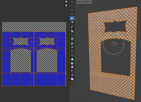
Figure 1: Usage of Live Unwrap feature.
Blender’s Live Unwrap feature makes UV mapping more interactive and intuitive. It can be enable in the UV editor or 3D View tool settings. Once active, you simply pin key vertices and adjust them, and Blender recalculates unwrapped regions in real time. This removes the need to manually unwrap multiple times as seams are added or moved, saving time and effort. I have always used the method of marking edge seams then unwrapping it, then finding a mistake then I have do the whole process again, which waste a lot of time. However, with this feature, I am able to quickly correct the issue and save valuable production time.

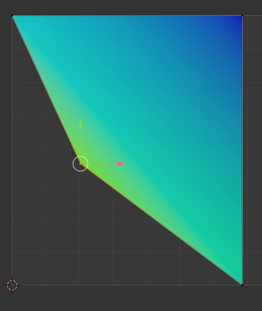
Figure 2: When not stretch, colour remains solid blue. [Left] Figure 3: When stretched, colour notifies user. [Right]
The UV Stretch overlay works hand in hand with Live Unwrap. When enabled in the UV editor overlays menu under Display Stretch, it shows a heat map of distortion. Areas coloured green indicate little stretch while hotter colours such as yellow or orange reveal potential problematic distortion, whether in surface area or angles.
Together with Live Unwrap and the UV Stretch overlay offer a streamlined workflow for clean and accurate UV layouts. Real-time recalculation lets you iterate quickly and catch errors early. The visual overlay highlights distortion that could affect texture fidelity. This features helps in texture baking or 3D painting to go more smoothly. Beginners and seasoned users alike can benefit from this practical and efficient UV toolkit.
As useful as the features appears to be, I encountered a frustrating issue when using Live Unwrap in Blender. After marking seams and adjusting UVs in the UV Editor, I would often realise I missed a seam or accidentally marked one while Live Unwrap was still active. Blender would then immediately re-unwrap the entire mesh, erasing all my previous adjustments. This forced me to redo the manual tweaking I had already completed, which was time-consuming and redundant.
Fortunately, there is a workaround that I have thought about and it has helped streamline my workflow. I now mark all the required seams first, then disable Live Unwrap. Once the initial seams are locked in place, I re-enable Live Unwrap only when I need it. This prevents automatic re-unwrapping during detailed UV adjustments and saves me from overwriting my previous work. Other artists also mentioned that keeping it off when not needed during seam work helps preserve pinned UVs and prevents unexpected resets (Lampel, 2021).
References
Kaspar, J. and Thommes, S. (2024) A UV Unwrapping Guide. Blender Studio. Available at: https://studio.blender.org/blog/a-uv-unwrapping-guide/?utm_source=chatgpt.com. [Accessed: 1 June 2025]
Lampel, J. (2021) Ultimate Blender UV Unwrapping Guide: 26 Key Tips for Subdivision Surfaces. CGCookies.com. Available at: https://cgcookie.com/posts/essential-blender-tips-for-uv-unwrapping-subdivision-surfaces. [Accessed: 1 June 2025]
Smeaf. (2022) I made 100+ UV Maps to learn this ONE Lesson.. YouTube. Available at: https://youtu.be/kZaa8MJyGBs?si=a5iMb0CwrLrPLHVP. [Accessed: 1 June 2025]
1 note
·
View note
Text
Final Masters Project: Scaling Down & Blockout

Figure 1: Old block out.
With the limited time allocated for this semester and additional responsibilities coming up, such as planning where to live after my Master's etc, I took the opportunity to review my earlier blockout from the pre-production phase. I realised that I had been too ambitious with the deliverables, originally planning to develop four major areas using only custom-made assets. These areas were colour coded, with blue representing the kopitiam (coffee shop) interior, green for the front-facing exterior, yellow for the surrounding area, and red for the distant buildings meant to cover the empty space in the environment.
To keep the project manageable and well-polished, I decided to focus only on the blue and green areas. The yellow and red areas are now considered stretch goals and will only be developed if time allows.


Figure 2: Kopitiam shophouse exterior. (Anushka, 2025) [Left] Figure 3: Kopitiam shophouse interior. (Anushka & Ong, 2025) [Right]
As a refresher, Figures 2 and 3 show the concept art created for this environment. While reviewing them, I noticed a few minor inaccuracies in the details. Rather than redrawing the concept art, these will be corrected directly in the 3D models during the production stage.

Figure 2: Exterior camera view of exterior blockout.

Figure 3: Interior camera view of interior blockout.
Blockout models of the exterior were created in Blender and then imported into Unreal Engine. Several placeholder blocks were also placed inside the shophouse to represent the intended space allocation for interior furniture.
This process helped to visualise how the environment would appear in Unreal Engine and allowed for the placement of fixed cameras to document the project's progress as it develops from the ground up and through the many development stages.
0 notes
Text
Final Masters Project: Documentation.
For the documentation process of this final Master's project, Notion, a project management application, was used to visually track productivity and briefly log progress. The modelling tasks were categorised into three main parts: the kopitiam (coffee shop) shophouse interior, the shophouse façade exterior, and the stretch goal of the surrounding area. Other important non-production or overview tasks are also included, on the right side of figure 1, such as symposiums, submission and presentation dates, overview of each area production status, lighting, post-processing, assembling the environment etc.

Figure 1: Notion Screenshot. (Access here)
As the interior features the most distinctive large-scale models and will be viewed up close by the audience, these elements were prioritised and scheduled for modelling first, categorised as high priority. Medium-sized props fall under medium priority, while smaller props are considered low priority. Currently, the interior includes 12 high-priority, 9 medium-priority, and 7 low-priority models. The exterior comprises 7 high-priority, 4 medium-priority, and 1 low-priority model.

Figure 2: Example of brief development logs. (Access here)
The development log follows a structured process which are key points and development decisions are briefly recorded in Notion, accompanied by screenshots for visual tracking and self-evaluation. This allows for smooth evaluation and logging throughout production. More formal and reflective blog posts are then published on Tumblr as part of the official development documentation. Additional platforms such as Polycount and 3DHit are also used to share progress and gather feedback from industry professionals.
Notion was chosen for this project due to its proven effectiveness during my Bachelor's Degree final year project in Video Game Development. The same method was employed successfully to manage asset creation for three major locations within the game environment, contributing to the project's overall success. Additionally, Notion’s ability to create shareable published pages allows lecturers, peers, or industry professionals to easily access my development progress, which supports both transparency and constructive feedback throughout the process.
0 notes
Text
Final Masters Project: Planning Folder.
During the week before our final semester where we would need to develop our final Degree Masters Project, we were instructed to work on a planning folder which consists of the following information:
Project concept.
Deliverables of this project.
Target audience.
How will audience access / view the project.
Project planning and time management (Gantt Chart).
Solution if any ethics, legal or contractual issues if they were to occur.
Risk assessment.
How will the project documentation be documented.
Learning outcomes matrix.
Personal learning outline.
Personal career goal.
All of the information above can be access through the link here.
However, as a short summary:
This project will bring a colonial-era Malaya to life in Unreal Engine 5, with a detailed kopitiam (coffee shop) shop house interior and matching exterior façades. I will document my progress through Tumblr development blogs and a Notion board, and gather feedback via simple online surveys, emails to industry professionals, and threads on 3DHit and Polycount. The main deliverables are the UE5 environment file, a promotional video, and if time allows, a PDF art book of key visuals will be produced. My target audience are Malaysians of Chinese heritage, Malaysians, and other Southeast Asians who may feel disconnected from their family history. The environment will tell their story through visuals rather than text. A clear Gantt chart guides my schedule, with stretch-goal tasks deprioritised if core modelling takes longer than planned. All free or third-party assets will be fully credited, and any feedback or cultural concerns will be addressed promptly and respectfully. This work will showcase my environment-art skills and support my goal of joining a top UK game studio.
0 notes
Text
F.M.P Pre-production: (Final Master Project Gantt Chart Planning)

Figure 1: Final Master Project Gantt Chart Planning.
I began my final master’s project's pre-production phase on the 17th February 2025 with a fifty days that was dedicated to planning, concept research, experimenting, and gathering resources. Although I had only counted weekdays for tasks, when I include the weekends this phase actually spanned seventy calendar days and wrapped up on 28th April 2025. Immediately afterward, I would deliver my pitch presentation on one of the three workdays from 28 April to 1 May and officially conclude the preproduction stage.
On 21st May 2025, A formal review of my proposed project and complete a project outcomes agreement with my university. I had set aside five workdays but the process took seven calendar days and concluded on 28th May 2025, as per instructed in the assignment question page in Canva. The very next day I would launched into document work, drafting my report, gathering feedback and refining both text and visuals. I estimated fifty seven workdays for this yet including weekends the task stretched until 18 August for a total of eighty one days on the calendar. It would not be continuous but whenever there is progress, there will be documentation in the blogs. It will be updated in this Tumblr blog page.
Starting on 29th May 2025 I would begin the production phase which is modelling. I planned for thirty-one workdays but it will take forty-three calendar days and hopefully finished on 11th July 2025. Within that timeframe I would work on the first floor for six days, built the interior furniture over sixteen days, shape the rest of the building shell in thirteen days and add surrounding shophouses in the remaining eight days.
On 11th July 2025 I would move into texturing tasks of the production phase. I had reserved fifteen workdays for painting and detailing yet including weekends it lasted until 1st August 2025 with a total of twenty one days. During that stretch, I will be texturing the interior in eight days, the exterior in six days and polished all remaining details in seven days. That same evening I would also be assembling the full scene in Unreal Engine 5. Environment building reserved six days and lighting and post processing will take another five days wrapping up by 12th August 2025.
In the second week of August, the recording of my promotional video will take place. I expect three workdays but with breaks, it took five days from 7th to 12th August 2025. I then will prepare my presentation slides in a single day on 15th August. 16th to 17th August will be the days for any last minute changes or finishing up the last few documentation blogs. Finally, I will then deliver my FMP presentation on either one of the arranged time slot on one of the set four days between 18th to 21st August.
Hopefully everything will go according to the above planned Gantt chart. With determination, passion and self-discipline, I believe I am able to carry out great results
0 notes
Text
F.M.P Pre-production: (Forefront [Giovanna Barcelos] )
Figure 1: Giovanna Barcelos's Corners of Croatia - Demo Reel 2024. (Giovanna Barcelos, 2024)
For today's forefront research, I went with Giovanna Barcelos’s breakdown of her Corners of Croatia environment and was impressed by how deliberate her process felt at every stage. She began by immersing herself in the streets of Dubrovnik and Split through maps and photos, using PureRef to keep her references organised.
Figure 2: Giovanna Barcelos's grey box. (Barcelos and McKenzie, 2024)
That solid base let her grey box the scene in Unreal Engine with simple blocks, ensuring scale and layout were sound before any detailed work began. As evident by her grey boxing, Investing time in gathering diverse images and testing proportions can save countless hours later on.
Once her blockout was locked in, Giovanna turned to modular design. She made a concise list of every window, door and street element she would need, then built a small kit of reusable pieces. By varying scale and rotation she filled out a large townscape without remodeling each asset from scratch. In my final masters project I intend to break shophouse details into a similar kit of modules so I can populate streets quickly while still keeping each corner feeling fresh. Two to four of the buildings next to the main highlight building will be of the similar style while the other buildings will be and older and smaller style. By creating two unique sets of modular kits like Giovanna did, I should be able to populate the area quickly.

Figure 3: Giovanna Barcelos's brief explanation on how she employed Flood Fills in her materials. (Barcelos and McKenzie, 2024)
Her next key step was creating tile-able materials in Substance Designer. She leaned heavily on flood fills and branching nodes to generate rich height and normal data, which she then used for cobblestone floors, stucco walls and carved trim. Seeing how a handful of masks can give a flat plane the look of layered brick and wear taught me the power of procedural texturing. For my environment, specifically the outside 5-foot walk way and public road, I plan to implement the flood fills method and her node network to introduce organic variation without painting or texturing every tile by hand.
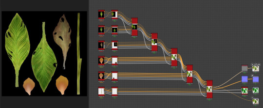
Figure 4: Giovanna Barcelos's foliage atlas in substance designer. (Barcelos and McKenzie, 2024)
Giovanna’s process for creating foliage atlas and models began with blocking out plant placement using simple Quixel Megascans placeholders to plan variation and density. For plants like hostas, ivy and hydrangeas she sculpted high poly leaves and baked their normals, occlusion and curvature onto low poly planes in Substance Painter. For more complex patterns such as canna lily veins she turned to Substance Designer, using procedural nodes and sliders to generate multiple leaf variations in a single atlas. Smaller plants were hand‐assembled in Maya with simple plane kits, while fuller vegetations like ivy were shaped in SpeedTree and then baked back into atlas textures. By combining these atlas maps with lightweight geometry she achieved a rich sense of organic depth without overloading the scene. I planned to create small foliage growing on some of the older nearby buildings. Hence, this section of the article is the most useful part for me as other places on the internet are not straightforward or not in the art style I plan to recreate.
Reference
Barcelos, G. and McKenzie, T. (2024). Learn How to Make A Realistic Modular Environment in Unreal Engine 5. [online] ArtStation. Available at: https://80.lv/articles/learn-how-to-make-a-realistic-modular-environment-in-unreal-engine-5/. [Accessed: 24 March 2024].
0 notes
Text
F.M.P Pre-production: (Forefront [Jessica Canales] )

Figure 1: Jessica Canales's The Mabuse Lab - UE5. (Jessica Canales, 2025)
For the next forefront research, I choose Jessica Canales’s breakdown of her Mabuse Lab project, and I am impressed by how she balanced technical rigor with storytelling in one large scale hard surface scene. She managed to fill her environment with sixty six props, twenty eight modular pieces, organic creatures, decals and complex shaders, all within a sixteen week time frame. Seeing her combine modular workflows with trim sheets to add fine detail without exploding her asset count was a real eye opener.
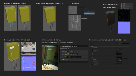
Figure 2: Jessica Canales's hard-surface assets pipeline. (Levine and Jessica Canales, 2025)
Her use of a mid poly workflow to develop her hard-surface assets, showed me how I can avoid a heavy high to low poly process while still capturing crisp edges and surface detail. I love how she merged face weighted normals with RGB masking and material layering to drive wear and tear effects in Unreal Engine's material layering system. I have not heard of this process before and will definitely adopt this into my development pipeline. That approach is something I plan to adopt for my interior furniture and some of the exterior parts that is more exposed to the elements, so I can quickly iterate on different levels of weathering and damage, without the need to return to substance painter to do changes there and re-import into unreal engine.

Figure 3: Jessica Canales's usage of decals. (Levine and Canales, 2025)
Her storytelling through decals, such as papers on the floor, water leak stains, and handwritten notes, gave her lab a sense of history and urgency. I want to bring a similar level of narrative detail to my kopitiam (coffee shop) environment, perhaps by placing leftover coffee cups, valuable belongings left behind, property or business documents, or family photos in key areas to hint at stories left untold or forgotten.
Jessica’s work has given me a clear roadmap for integrating modular design, advanced texturing, narrative details and cinematic lighting into my final master's project. There are several new process or Unreal Engine features that I have not heard of and I look forward to trying them out.
Reference
Levine, G. and Canales, J. (2025). How To Create A Detailed Large-Scale Scene With Rich Props & Assets In Unreal Engine. [online] 80.lv. Available at: https://80.lv/articles/how-to-create-a-detailed-large-scale-scene-with-rich-props-assets-in-unreal-engine/ [Accessed: 28 April 2025].
1 note
·
View note