
This blog is about my spare time projects or stuff that matters to me such as electronics, reverse engineering, computer science, embedded devices, security or digital forensics. It is not affiliated to my employer in any way. Posts may be either in...
Don't wanna be here? Send us removal request.
Statistics
We looked inside some of the posts by jmichelp and here's what we found interesting.
Average Info
Notes Per Post
2
Likes Per Post
1
Reblog Per Post
1
Reply Per Post
0
Time Between Posts
2 months
Number of Posts By Type
Text
11
Note
5
Link
1
Last Seen Tumblr Blogs


Fun Fact
The KCSC sent more than 20K requests to delete posts related to prostitution and porn to Tumblr from January to June 2017.
Text
About my “lab”
Welcome to my electronic lab! Over the last few years or so many people asked me about my personal lab, so today I am giving you a virtual tour of it.
We will go over what gear I use and how I set everything up so I can do my experiment efficiently. Along the way I will answer the questions that has been asked about my setup in my various posts. In particular, I will provide a rationale of why I choose one type of hardware versus another. The quantity of hardware described in this post might seems overwhelming but keep in mind here that it took me years to build this lab. I merely add a new piece here and there based of my needs and opportunity.
Disclaimer: I don’t claim my setup is the best but it works for my use-cases: tinkering with electronic, doing security research and repairing various pieces of equipment. If you have suggestions on how to improve it, let me know.
Overall setup
All my equipment is installed on a big and stable desk that I bought from IKEA (BEKANT model). As extra storage room, I used an extra thick shelf from IKEA as well (LACK model). Sadly the brackets (IKEA Ekby Töre model) used to fix the shelf to the desk without drilling are discontinued which prevents me from adding an additional shelf. If you know a place where I can find a similar product let me know.
All units are connected to an Intel NUC Swift Canyon barebone either via Ethernet or via USB when Ethernet is not supported. The NUC has 32GB of RAM and a 512GB SSD. This small PC allows me to handle the firmware upgrades, capturing screenshots of the different gears at once, handle the software defined radio (SDR) through its front USB3 port, dump NAND flash memories, etc. And the form factor is just great, leaving most of the space free. The 23” LCD screen is mounted on a Ergotron articulated arm. Again, the rationale here is just to keep the workspace clean.
To avoid damaging the wood of the desk, I put an ESD mat from Vermason. It provides a good protection and also has a standard ESD stud on each corner. I’m using that have a standard ESD wristband and the soldering station is also connected to it. I never felt that ESD protection was mandatory but considering that the mat was the most expensive piece in having the ESD setup done, I thought it was worth buying the few cables required to connect the mat to the ground through a 1M resistor and have the soldering iron properly connected too.
Finally, to provide power to everything on the desk, I am using a huge outlet (thanks to the very efficient form factor of the Swiss power plugs compared to the big fatty European one that I had to use when I was living in France) that provides me not less than 16 plugs!
Soldering, desoldering, and accessories
Of course we couldn’t talk about an electronic lab without starting with soldering and desoldering equipment. No matter what you’re doing, it’s really mandatory to have a soldering iron where you can control the temperature. Otherwise it’s like being a butcher who only uses an axe to cut the meat. I used noname stations for a while but at the end it always ended up the same way: something breaks or you want to change the tip of the iron but the model is discontinued and you cannot find spare parts anymore. So I decided to stay with a known brand and I bought a JBC soldering station. Be careful, it is super expensive. Really! But it is also amazingly good. It heats up almost instantly, I can have up to 4 different irons connected to the control station, I can change the tip of the iron in 2 seconds without burning my fingers. It’s just fantastic and modular but I also acknowledge that not everyone can afford it and may prefer cheaper alternatives such as Weller or Hakko which are very good too. I use a DME-2A control station with 3 tools (and stands):
a T245 iron for general purpose soldering (through hole component, drag soldering SMD, etc.) with tips/cartridges C245-102 (2mm bevel tip), C245-759 (2.4mm chisel) and C245-931 (2.7mm spoon)
a T210 iron for precision soldering with the cartridge C210-019 (0.2mm chisel)
a PA120 micro-tweezers iron with C120-002 (0.2mm tip) which is pretty convenient for soldering or reworking SMD components, especially the small form factors such as 0402 or smaller.
For desoldering, nothing beat a hot air gun. Classically hot air guns are provided in the shape of a big chunky control station with an embedded air pump. I used to have such station but it was big, heavy, the cable transporting the hot air was warm, the air flow was somehow disappointing (ok, it was a noname station so it was definitely not a high end one), and at some point the air pump died. Finally, after seeing a review from Dave Jones (EEVblog), I opted out for the tiny cheap Atten 858D+ station and honestly it just works perfectly well for me. Even if it breaks at some point, it’s nothing but a radial fan in the gun and a heating element in the nozzle. It’s just super easy to service.
One need to protect his lungs because even if we have two, the second one is not there for high availability. So it’s important to have a fume extractor. Nothing fancy here. I just bought an extra filter from the beginning. If you think a fume extractor is not necessary, I encourage you to watch the video from Louis Rossmann on Youtube.
Finally, you will also need some accessories such as a tip cleaner, tweezers, soldering wick, flux, solder, and side cutters. I haven’t put links everywhere because there’s nothing too critical except the diameter of the solder: just be aware that to do very fine pitch soldering, you need to have a very fine diameter solder. Soldering 0.5mm (or less) pitch components is not going to work well with a 2mm diameter solder.
Another accessory that I added recently to my setup is a PCB holder. After having spent quite some time looking on the Internet, I opted for PCBite and it’s really really good. Sturdy, durable, comfortable to use. I even think about buying a second set.
Inspection
As soon as you start soldering SMD, you may want to have a closer look at what you did to ensure that all the solder joint are done correctly. And for that, nothing beats a real optical microscope. You may think that a USB microscope may do the job or that a magnification glass/lamp could be enough. I tried them and they will never provide the same kind of feedback. Using a USB microscope that will show you things on a remote screen is a bit awkward because you’re moving your hands but you’re not looking at them. Maybe it’s just a matter of habit but I didn’t like it. And with the magnification glass, I was lacking the feeling of depth: having both eyes looking through it, it couldn’t reliably tell which hand was on top of the other. So, since the beginning I was using a binocular microscope. But then, with the blog or for publications, I wanted to take pictures of what I was seeing through it. Also on my previous microscope the working distance was pretty small and soldering without having the iron touch the microscope and burn it sometimes implied some uncomfortable positions for my hands. So I recently upgraded that microscope for an AmScope trinocular SM-8TZ-144S-10M. Again, the rationale behind the choice of the articulated arm is that I can push the microscope away when I don’t need it, freeing some space. The trinocular setup allows me to mount a proper Bresser 1080p HD camera on it. I replaced the 10MP camera that was provided because the videos were not as smooth and I would like to be able to shoot some movies of my work in the future. The only disappointment here is that the microscope is not simul-focal. This means that I have to choose between the camera and the left eyepiece; I can’t have both of them at the same time. If I had to rethink that choice, I would definitely go for a simul-focal model. The camera is connected through HDMI (the USB2 output could not sustain full HD resolution at 30fps) to a Magewell XI100DUSB-HDMI capture dongle that sends the feed to the NUC.
Measuring
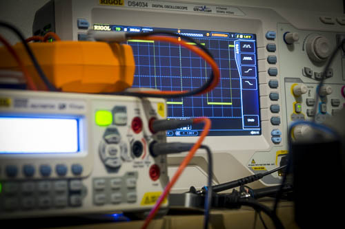
The oscilloscope is for the electronics what a good debugger is to a developer or a reverse engineer: a must-have. My first digital oscilloscope was a Mixed Signal Oscilloscope (MSO). But I was a bit disappointed of the logic analyzer and honestly I had no use of having both the analog and the digital signals on the same tiny screen. Therefore I changed it to a Rigol DS4034 oscilloscope. There was recently a sale and it came with the full bundle of options (all protocol decoders, advanced trigger options, and a bandwidth upgrade included) for free which makes it actually a Rigol DS4054 with 500MHz bandwidth. It has a very wide screen and while 2 channels would cover most of my need, there are times when 4 channels are necessary. Unfortunately, the software Rigol provides is not the same quality as their scopes: even with a 100Mbit/s Ethernet link, the UI is not fluid at all. It’s enough to make high quality screenshots without using a USB key but it’s unusable to make video or even control your scope in real time actually. An alternative software called Rigol UltraVision Utilities is available for free on the EEVblog forum and is much better than the official software. But the refresh rate is still not enough for good videos so I may consider in the future using the VGA output of the scope and plug it into a USB capture card connected to the NUC.
An oscilloscope is not enough though; you also need multimeters. And yes, I’ve written that in plurals because you may think about having 2 multimeters: one for measuring the current and the other one for the voltage for example. I’m using a Rigol DM3068 bench multimeter. It has a superb accuracy (6½ digits), covers great ranges of measurements and provides 4 terminal measurements if needed for a reasonable price. The only bad thing about it is that the continuity tester is really slow (i.e. the time between you probing a circuit and hearing the multimeter emitting a beep is long). For my second multimeter I chose a handheld model, an Agilent U1273AX which is a really good piece of gear. Of course, as you would expect if you’ve followed my philosophy when it comes to choosing equipment, I also bought the infrared to USB cable to stream the results back to the NUC.
Nowadays most the electronic world and protocols we can see on a given device are digital and to have a closer look at those, we need a logic analyzer. Like many others, I picked a Saleae Logic one, more precisely the Pro 16 model. Pros are that it simply streams the samples to the computer, it does that over USB3, can sample at up to 100MHz, and has an SDK to allow you to write your own decoder. The main drawback for me is that the samples have to be buffered on the computer and only when you stop capturing you can see them on screen and use decoders. I would prefer to have a “real-time” option here. Also the 100MHz sampling frequency can be an issue when the bus you are looking at goes above 50MHz due to Nyquist limit.
Finally, because I also do some electronic repairs, I added to the lab a programmable electronic load. This allows me to easily test power rails which are usually the first thing to fail on a device, by setting constant current, constant voltage, constant resistance or constant power mode. Very handy to test those cheap power adaptors. Mine is a BK Precision 8601, connected to the NUC over USB.
Powering
Should you be experimenting, prototyping or analyzing an equipment, you will need to power the device in a long term, reliable way. And for that you will need a bench power supply. Mine is a Rigol DP832A that I haven’t chosen for it’s cheesy colors on the front panel but for its high precision.
To complement my setup I also added last year an arbitrary waveform function generator, or ArbGen, a Rigol DG1062Z. I kept it with the native 8Mpts memory even though it has physically 16Mpts memory inside and can be unlocked through a software license upgrade. But I’m not using it to generate complex signals at the moment therefore 8Mpts is plenty enough.
Prototyping, debugging, reverse engineering
Another essential piece of equipment that you will need are breadboards. They allow you to quickly prototype something without soldering anything. And to be complete here, you will also need jumper cables here. Personally I bought fairly expensive ones from Schmartboard but they are more durable than the cheap alternatives which tend to break easily. I have an assortment of male-male, male-female and female-female cables.
To easily interface with any device, I also have a bunch of Teensy 3.2. I just love their form factor and they are very powerful: with overclocking, the Teensy 3.2 can go at 96MHz and it embeds a DSP for complex math computation! I also have a RaspberryPi 2.
If you have read my previous articles or if you follow me on Twitter, you should already know that I also have most of the boards derived from the GoodFET project: GoodFET, FaceDancer (USB), GoodThopter (CAN bus) and ApiMote (Zigbee).
I also have a bunch of FTDI development modules such as the FT2232H, FT4232H and UM232H. They can be used to dump NAND memory, quickly interface with serials protocols such as RS232 or RS485 and also act as a fairly fast (~20MHz) JTAG interface that is compatible with OpenOCD. The smaller module even comes in a breadboard-friendly format.
To deal with (E)EPROMs and/or flash memory chips I have a TNM5000 with all the adapters, including the optional TSOP56 for NOR flash that I had to buy separately. I also have a PICkit2 and a PICkit3. The main reason about having both is that the PICkit2 is compatible with Linux. But newer Microchip MCUs require a PICkit3.
When it comes to RFID, I have a Proxmark3 from RiscCorp that I recently upgraded to Proxmark3 RDV2. It comes with much better antennas (sometimes they are a bit too good actually) and in a nicer form factor without the stupid Hirose to USB cable. Also it has a more modern micro-USB plug instead of a mini-USB.
For radio frequency investigations, I have bladeRF x115 since I was part of the Kickstarter campaign with its optional transverter XB-200 for lower frequencies. But that’s not a surprise considering that I am the author and maintainer of the SDRSharp plugin for it.
I also have a bunch of Chipcon/Texas Instrument dongles: CC1111EMK, CC2511EMK and CC2540EMK. They are very handy to quickly deal with some sub-GHz protocol with RFcat or to sniff at Bluetooth LE packets. I also have the complementary Chipcon debugger which allows in conjunction with SmartRF Studio to experiment easily and reflash the dongles with the RFcat firmware (but a GoodFET would have been enough for that purpose).
In order to deal more specifically with Bluetooth and Bluetooth LE protocols, I have an Ubertooth One dongle
I also participated at the crowd funding campaign of Chipwhisperer but I haven’t got the time yet to go through all the documentation and tutorials to use it effectively.
And for more high speed or complex protocols, I have a Terasic Altera Cyclone IV FPGA development kit which allows me through its extensive set of mezzanine boards and GPIOs to interface with pretty much everything provided I spend enough time writing Verilog/VHDL for that.
Conclusion
It makes a quite long article and I hesitated to cut it into several parts but as some choices I made are somehow linked between the categories, I thought it would make more sense to have everything in one single article. I also hope that it will be helpful to some of you and don’t hesitate to tell me in the comments section.
0 notes
Note
Hello Jean-Michelle, I have a question about the artivel 'From NAND chip to files'. I copied the content of a NAND chip to a bin file with TNM5000, the bin file is approx. 4,5 GB. Do you have any idea about how to read the files from the bin file? I tried to mount it in Linux but it seems the maximum size is 256MB. Thank you for your help! Best regards, Laszlo
Hello Laszlo,
there is indeed a step I haven’t detailed enough on my blog post. Sorry for that.
In my article, I was simply stripping off the OOB data because by looking at the dump, it was easy to tell that the file system was UBIFS. The particularity of that filesystem is that it does not rely on OOB for the Flash Translation Layer (FTL) and this is why I had no use of it.
NAND flash memory technology implies that you can only write by turning bits from 1 to 0. When you want to do the opposite, you have to request an erase operation. Unfortunately, that operation can only happen at a page level. Therefore when you are simply changing a small amount of information, it’s more efficient to duplicate the page to an empty one with the byte changed rather than reading the page, erasing it and then writing it back with the changes. Also, just like your cellphone battery with slowly age over time, a flash memory page can only sustain a certain amount of erase cycles before degrading. In order to optimize the life-span of a NAND flash, people started using Flash Translation Layer: the OOB area is leveraged to store metadata such as error correction code (ECC), whether or not the page is “deleted” and also the index of the page in the filesystem.
Once you’ve understood the FTL (which is implementation specific), you are able to filter out the “deleted” or “invalid” pages and re-order the flash pages in a linear order. At that moment you can remove the OOB data and you end up having a file that is the equivalent of a disk image. Depending of the filesystem being used, you may be able to mount it on Linux without having to create a virtual flash chip.
I hope this clarifies a bit the steps required to handle NAND flash dumps.
If I manage to find a good (and simple enough) example, I may write a more detailed article about going from the chip to a mountable disk image when you have to deal with an FTL. But I have no idea when this will happen as I already have some other articles waiting.
0 notes
Note
Hi Jean-Michel, I'd like to dump the firmware of my Samsung SM951 M.2 NVMe drive. Do you know how to do that?. If so, could you create a tool to dump firmwares of SSDs (SATA/M.2). I'm telling you this, because there are many people like me that are looking for a tool or utility to do that, but it haven't appeared yet. Thank you!!.
Hi,
Unfortunately, the manipulation of hard drive firmware is, most of the time, done by sending proprietary ATA commands to the drive. Those commands are never documented by the manufacturer and may change, for a given manufacturer, from a drive model to another. This can explain why such off-the-shelf tool does not exist.
In order to extract such firmware, either you are lucky and the manufacturer left the access to the JTAG port of their ASIC open or you will have to reverse engineer one of the firmware upgrade tool they may provide on their website. This can require a substantial amount of work and you will only obtain the firmware writing commands with such method. Turning that into a reading primitive may be harder than it seems and can brick your SSD in the process. Of course if you only care about extracting one firmware (i.e. not necessarily the exact one currently being run by your disk), you may be successful extracting it directly from such firmware upgrade tool. I have never done that so I cannot tell you whether or not the firmware is secured by some cryptographic primitives (e.g. if the firmware itself is sent encrypted to the drive and the disk knows how to decrypt it to finish the upgrade procedure, you may be stuck).
Also, pay attention to the laws and regulation of the country where you are currently living in: reverse engineering may be illegal or may be permitted only for a specific set of reasons.
0 notes
Text
Frequently asked questions... and a bit more
Wow, it’s been quite a long time since I have written in that blog! It also seems that I received many questions but I never received the notifications. I’m sorry for that. This seems to be related to some automatic changes on the settings. Problem should now be fixed.
Considering that I now have to answer a bunch of questions (received either by email or through this blog) and that many of them are overlapping in some way, I decided to do a sort of FAQ post instead of replying individually.
If you asked me a question and you don’t find an answer in this post, don’t be shy and ask again, either through the dedicated section on this blog or by email.
Is this blog dead/abandoned?
Short answer: no it’s not otherwise you wouldn’t be reading this :)
I have many ongoing projects but I haven’t made significant progress to publish something about them yet.
Then, why is it so quiet?
Well, I’ve been pretty busy during the last two years and this blog is only about the projects I do on my spare time. I got a new job, I moved to another country and I have to learn a new language in order to be able to talk to people outside of the office. All of these things take quite some time.
I tried to use your project XXX without success, can you help me? I found a bug in your project XXX, can you fix it?
The rule of thumb here is simple: if the project is living in my Bitbucket or in my Github account, then, please, use their corresponding section to open a bug. It really makes my life easier and I really do my best to keep those opensource projects up-to-date and fix bugs as fast as I can.
This is particularly true for scapy-radio, DPAPIck and bladerf-sdrsharp projects. And of course you can submit feature requests the exact same way.
I can’t make YateBTS work with a BladeRF, can you help me?
First, I am not affiliated to those projects in any way. I’m nothing more than a regular user here. Those two projects are evolving pretty quickly and it can be a bit tricky to find matching versions that are working together. As I’m not maintaining a working setup, the best way to get help would be to report the issues your are facing to the users forums of each project.
I asked you a question and got no answer, why?
Sometimes, people are asking me questions through this blog but I consider the answer being too sensitive to be shared publicly. But if you asked the question anonymously, you’re not allowing me to reply to you personally.
Conversely, if you’re putting personal information in the question (e.g. an email address), I won’t be able to answer the question in the blog. I simply can’t edit the question you sent. I can either answer it privately (if it hasn’t been posted anonymously) or answer publicly on the blog.
What kind of hardware/software are you using?
That’s actually a question I’ve been asked not only on this blog but even by persons I happened to meet. The answer would take quite some space though, so I will keep it for a next post on this blog (I will update the FAQ with a link once the post is ready). That being said, I try to pay attention to list the tools (both software and hardware) that I used for a given post.
Could you help me re-implementing DPAPIck in C++?
This project took me quite some time and implementing it in Python as well as opensourcing it under GPLv3 was not a reckless choice. I’m always happy to receive feedback, bugs or feature requests because that means that people are using it. I’m even happier when I receive pull requests!
But considering that my spare time is a limited resource, I can’t afford spending time supporting a fork when I’m already having hard time to add support for modern versions of Windows or to add new probes or new features (and trust me, I have a lot of ideas to implement here and make DPAPIck more powerful and easier to use). Big kudos to Francesco Picasso who has been the only one so far to contribute to the code base and to Gentilkiwi who always share his findings regarding DPAPI with me so that I can quickly implement them.
Do you accept consultancy requests?
Sorry but I already have a full-time job and a salary and I’m not considering working 24/7 without sleeping. There are only very few corner cases where I might consider contribution to external projects. But your project as to meet quite a lot of criteria...
Will there be a follow-up article on Vingcard?
I don’t think so. I think I’ve published enough details about it to make people aware that their system should not be considered as secure and that there are better ones on the market.
Raising awareness and messing with a business model of a company are two different things and I’m not keen at all on doing the second one. So there is no way I would disclose anything about Vingcard proprietary algorithm and allow people to counterfeit their cards.
Could you write an article about XXX?
If I found the subject interesting enough and if I have enough knowledge on that topic, I probably will indeed. So far I publish about projects (or parts of the projects) I’ve been working on. But I can also take into account external ideas provided it doesn’t require many weeks of work on my side and that I found the idea interesting and ethical.
I tried to recover a NAND flash the same way you did without any luck, why?
There’s one thing I forgot to mention when I wrote the article: Flash Translation Layer (FTL in short). The NAND I dumped in my article was using UbiFS which happens to be a simple and “flash friendly” filesystem. This is unfortunately not always the case and the out-of band data of the NAND that I stripped away of the dump is usually used to construct an FTL. To keep it simple, part of this data will be used to tell in which order the flash pages should be put in order to get a valid dump. UbiFS has been designed to incorporate this information in the filesystem itself and this is why I could strip the OOB area. Also, there is not one unique way to write the FTL to the OOB area. Therefore one must first analyze the FTL before trying to mount the flash and recover data.
Could you advise some books to read?
Unfortunately, I’ve learned most of the stuff I am publishing on my blog as a hobbyist. My bookshelves actually don’t have books related to electronics and I think that nowadays, it’s easier to find good materials on the Internet rather than finding a good book in a library, especially when it comes to computer science and/or electronics.
One advice I could give though is that I always found it useful to learn and understand how an electronic engineer would design something in order to better know where to look in order to analyze it. It could seem silly or obvious but if you want to be able to understand how a cake is made by looking at it and tasting it, then you should start by learning how to cook.
0 notes
Note
Thank you for your reply at 7 January. I have a additional question about the demonstration in Airbus CyberSecurity’s blog. Would you please suggest the specifications (like the product name ) of your experiment equipment DOOR SENSOR, ZWAVE controller USB, ALARM DEVICE? Because I really want to follow your project! Thank you.
I am sorry but unfortunately I don't have the model/manufacturer references anymore. According to the pictures we took, I would say the USB controller is an Aeotec. The alarm was not selected to be from a specific vendor, we just took what was available on the market for quick delivery :)
0 notes
Note
Hello. I've wanted to contact you with the e-mail but there isn't any information about you. I have some questions about your project presented in Blackhat 2014. That's are about the ZWAVE protocol. Firstly, I downloaded the grc(Zwave in grc) files from the 'bitbucket'. Is it just for the sniffing the Zwave pkts? It can do the TX like directly turning off the Zwave light? and Could I get the demo videos and the descriptions about it ? Thank you!
Hi.
All the GRC files we provide are able to do both TX and RX at the same time provided the underlying SDR you are using is capable of full duplex. You may need to tweak the sink and the source blocks though is you are using GnuRadio 3.6+ with an Ettus SDR or if you are using another SDR.
Regarding the videos of the demonstration, they have been put online on Airbus CyberSecurity's blog
0 notes
Link
After a couple of years, I finally updated DPAPIck.
More information can be found on the website of the project.
Well, I have to admit that it’s been a long time since I wrote here.
Lot of people complained during the past years that DPAPIck was only supporting Windows XP and Vista and basically wanted to know if one day we were going to support newer versions of Microsoft Windows.
Thanks to Francesco...
1 note
·
View note
Note
Hi, i try use dpapick (python framwork) for offline dectioption the master key on windows 8 (AES256 and SHA512), but it couldn't decrypt it. Please tell my, is this project support my case ?
Hi,
The current version of DPAPIck does not support Windows 7 and later versions. However, Francesco Picasso successfully patched DPAPIck to support those versions of the operating system. He sent me the patch and I am currently reviewing/integrating it to allow seamless support of all Windows version from XP to 8.1.
Stay tuned, it should not take too long :-)
0 notes
Text
Reversing H.Koenig wireless remote (part 4)
During the previous part, we were able to use GNU Radio and a Software Defined Radio (SDR) in order to receive and demodulate RF packets.
Now is the time to go a bit further: extract and decode packets and then, the counterpart, encode and send packets back.
Even though I will use my robot vacuum as an example, this blog post can be considered as a simple how-to about writing a simple packet sink in GNU Radio.
First of all, we need to modify the previous graph flow we had in GNU Radio Companion (GRC), first reason being that we were using the scope as the output and we were doing it "the ugly way". Let me explain.
Last time we were using Rational Resampler and Threshold blocks to get a view of the bits that we were receiving, ie. we were resampling the signal exactly at its bitrate. There is a really big drawback doing this: the odds that your sampling clock is perfectly synchronised with the sender's one are... well... not that huge as you can guess :-)
That's why there is a magical block that will do the job for you: Clock Recovery MM. The main parameter to give to this block is expressed in "samples/symbols", that is to say, your sampling rate (samples/seconds) divided by your target bitrate (symbols/seconds). With that figure, this block will do its black magic to recover the clock of the sender and synchronise its work with it to extract your bitstream.
So, after modification, the flow graph looks like this:
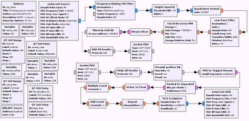
This version is more complicated but that's because it is able to both receive and transmit frames and I am going to detail everything about it. Don't be afraid and keep reading!
As it may not be easy to read it, click here for a full size capture.
The first new block that appear is Frequency Xlating FIR Filter. This does 3 things at once:
It shifts your signal in the frequency domain to recenter it. GNU Radio only processes signal at the baseband level and that's why, by default, your FFT is centered around 0 Hz. This operation is strictly equivalent, in terms of digital signal porcessing, as multiplying the signal from osmoscom Source with a generated sine wave which frequency is the offset you want.
It decimates your signal ie. it reduces the sample rate to save CPU resources. Here, I am simply dividing the samplerate by 2 so the output of this block will be at 2 Msps.
It filters the signal through the obscure Taps parameter. In the screenshot you only have an overview of the value but basically, I am building here, in Python, a Low Pass Filter. The filtering is applied after shifting so the goal of this filter is to isolate the signal you are interested in.
Why do we need to recenter our signal? Why not simply sniffing on the given frequency? Well, usually, SDR have a DC spike on the frequency you are tune at. This is done by construction and could not be easily circumvented. If you are used to the cheap RTL-SDR dongles, you should have never seen that spike because the output is AC coupled but the drawback is that the center frequency is unusable because a portion of the real signal has been canceled too in the process. So that's a common thing to listen to not-so-far frequency, recenter the signal and get rid of that ugly spike with a low pass filter.
As the low pass filter is already done in the Frequency Xlating FIR Filter, the Low Pass Filter block that was right after the Simple Squelch vanished. No need to waste CPU by filtering twice.
In the previous article, between our signal demodulator (Quadrature Demod block) and the Binary Slicer block, we had 4 blocks that are replaced by 2 blocks in the latest version of the flow graph. You are already familiar with the Low Pass Filter block so I won't explain it again. I am just doing extra filtering after demodulation to clean up the signal, nothing more.
And then we have the magical block, Clock Recovery MM. As I explained earlier, its role is to recover the clock of the sender of your signal to synchronise with it, hence its name. The only paramater you have to change in your flow graphs is the first one, Omega. I honestly don't know what the other values stand for at the moment (I am slowly starting to learn about DSP to better understanding what I am doing) but the default values are fine.
Finally, after the Binary Slicer we have a new dedicated block that takes bytes in its input and outputs messages. Let's forget about the last two blocks for the moment. This block, Hkoenig sink bb, is the one I wrote in C++ (mainly because I haven't find how to do it in Python) and I will explain here the several steps I followed and how it works. It has three main tasks to do:
Find the Access Code within the bitstream. If you look back, this part was previously done by the Correlate Access Code block. The goal here is to find the beginning of a packet with a given error tolerance
Extract the packet. In this case, it is very simple as we are dealing with fixed size packets. All we have to do is grab the bits until we have the right amount
Reject bad packets. Remember that we have a simple checksum byte at the packet. We are going to compare the computed checksum with the one receive through the radio and if we have a match, then we output the packet and resets our state automaton
First step is to create an GNU Radio OOB module by using the provided tool gr_modtool.
$ gr_modtool newmod jmichel Creating out-of-tree module in ./gr-jmichel... Done. Use 'gr_modtool add' to add a new block to this currently empty module.
Then we add a new block to this module:
$ cd gr-jmichel $ gr_modtool add -t general hkoenig_sink_bb GNU Radio module name identified: jmichel Language: C++ Block/code identifier: hkoenig_sink_bb Enter valid argument list, including default arguments: unsigned long access_addr Add Python QA code? [Y/n] Y Add C++ QA code? [y/N] N Adding file 'lib/hkoenig_sink_bb_impl.h'... Adding file 'lib/hkoenig_sink_bb_impl.cc'... Adding file 'include/jmichel/hkoenig_sink_bb.h'... Editing swig/jmichel_swig.i... Adding file 'python/qa_hkoenig_bb_sink.py'... Editing python/CMakeLists.txt... Adding file 'grc/jmichel_hkoenig_bb_sink.xml'... Editing grc/CMakeLists.txt...
The tool already created all the directory structure, files, building chain, etc. for us. Awesome! All we have to do is fill the gaps is some of the files.
First, lets edit lib/hkoenig_sink_impl.h:
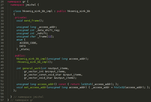
I added several things to this class:
send_frame() function is an internal function that will be called when a valid packet as been found
_data_shift_reg is our internal accumulator in which we will push the bits
_nshift just keeps track of how many bits we have pushed in the accumulator
_frame is our packet
the enum _state simply lists the different states of our automaton
access_addr() and set_access_addr() are simply accessors around the private item to allow this variable to be changed while the graph is running. Otherwise, by default, everything is passed on the constructor once for all.
Lets move to the code now, in lib/hkoenig_sink_bb_impl.cc.
First, lets see the constructor:
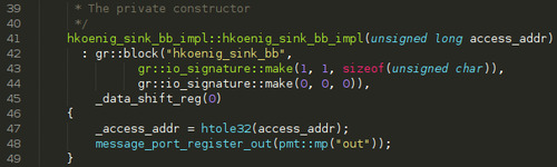
We simply modify the input io_signature (the first one) to have exactly 1 input (hence MIN=MAX=1) of bytes (unsigned char). As there is no way to build an io_signature for messages, we simply declare that our block as no output. Then we set _data_shift_reg and _access_addr to their respective values and finally, we register an output message port named out. That will be our output.
Now lets look at our main big function, general_work():
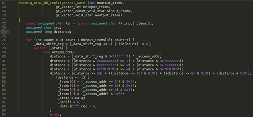
The code is available on my Bitbucket account so, if can't read it through the capture, just follow it there.
The general prototype of this function is able to deal with multiple inputs and multiple outputs. To make the code easier to read, the local variable in will be our single input stream.
Then, for every input item we have:
we push the bit to our shift register
our initial state is ACCESS_CODE and there, we XOR our current shift register value with the expected access address value. After four lines of mathematics trickery, we have the Hamming distance between those two values, that is to say we have computed the number of erroneous bits to get our access code. In the Correlate Access Code block we have used previously, this is the Threshold parameter.
If we have at most one bit of error (the value has been extracted by spying on the SPI bus on the real remote and analyzing the configuration values with the datasheet), we are good to process the frame. So we start writing the access address (the good one, not the received one that may contain one erroneous bit) at the beginning of _frame, we change our automaton state to DATA and we reset our _data_shift_reg and _nshift counter.
Here is the end of the function:
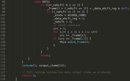
If we have shifted a complete byte (remember, shifting the bit is done before the switch/case statement), we append it to our _frame.
If we have completed a frame (ie. we have pushed 8*8 bits), we move back to the ACCESS_CODE state, we reset both _data_shift_reg and _nshift and we compute the checksum against the extracted frame
If the computed checksum matches the one seen over-the-air, we call send_frame()
finally, at the end of the for loop, we tell the scheduler that we have processed all items by calling consume() and we always return as we don't have a synchronous output of samples.
Now let's have a look at send_frame():
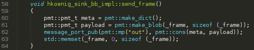
Very simple one, compared to the automaton:
We create an empty metadata dictionnary
We create a message blob from the _frame
We publish the blob and its metadata on the out message port
We reset _frame for the next one
If you have followed me so far through all this process, we still have one file to modify: the XML file that describes our block to gnuradio-companion and that also gives him instructions on how to generate Python code for our block. Normally, all you have to do in this file is configuring the parameters of your block (those passed to the constructor) and the names/types of both inputs and outputs. But here we have an extra line to write to tell GRC that we can change a parameter while the graph is running.
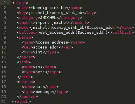
Nothing too complicated here except that the names may seem reversed for sink and source tags (in GNU Radio, a sink processes samples so it is your input whereas source produces samples so it is an output):
name is just the display name in GRC
key must be unique and match the corresponding parameter name in the make tag (preceded by a dollar sign)
type must be set to a valid Python type
our source type is message
the callback tag contains the public method to set the parameters that are given in arguments. GRC will understand that and will underline those in the GUI to inform you that they are runtime configurable.
Enough for the code, let's go back to our flow graph to continue the explanations. But first, a small digression. On 6th August 2014, two coworkers from Airbus DS Cybersecurity and myself were presenting at BlackHat USA 2014 a new tool we wrote and that my employer has let us release as opensource software. This tool is called scapy-radio and connects together scapy for packet dissection/manipulation with GNU Radio. Basically, it replaces your usual ethernet card by a Software Defined Radio to allow radiofrequency pentesting. If you haven't heard of that tool, I suggest you read our slides or our whitepaper because the next three blocks I am going to describe relies on that tool!
As described in our slides/whitepaper, Add GR header simply prepends the packet with our custom header that allows scapy to process it. Here, I have arbitrarily chose to use 128 as the protocol value. Conversely, Strip GR header is used on the transmission side to remove this header (we obviously don't want to send it over-the-air). The packet with its GR header is then sent to a UDP Client socket that connects back to scapy-radio. And we are done for receiving!
Briefly, I will also explain the transmission part:
Socket PDU UDP Server receives the packets from scapy-radio. Just note that the port is not the same as in the UDP Client socket.
Strip GR header has already been explained previously
Preamb prefixer bb is just another block I have written to prepend a packet with a configurable preamble. Preamble is required for the transmission to help the clock recovery system to synchronize with us but it is not part of the packet so we have to add it in GNU Radio. I won't go into the details of its parameters here because I will describe all my custom blocks on a wiki associated with the code repository.
PDU to Tagged Stream just extracts the blob in the message (our packet) and converts it back to a byte stream.
Packed to Unpacked will convert our byte stream into a bit stream.
UChar to Float will simply cast our bits (0, 1) into floats (0.0, 1.0)
Then we use the Multiply Const and Add Const trick I already explained to recenter our values from [0.0, 1.0] to [-1.0, 1.0]
Repeat will just duplicate each sample a given amount of times (consider that as a dumb resampler) to have the correct samplerate before modulation our bitstream
VCO (complex) is the block that will do FSK modulation. Its name means Voltage Controled Oscillator, the voltage being the sample value on its input. Sensitivity is the frequency deviation in hertz.
Finally we have our osmcom Sink that will send our modulated samples.
This flowgraph implements both the transmitter and the receiver. But you may wonder how to use this graph. I've mentioned scapy-radio and indeed we are going to use it. All you have to do is:
Get scapy-radio and compile/install it on your system
Get gr-jmichel and compile/install it too
copy my flowgraph from examples/hkoenig_vacuum.grc to $HOME/.scapy/radio/
use my Python script apps/gr-hkoenig-scapy.py
Without any argument it will sniff for packets and print them on the console. If run in interactive mode it will give you a scapy-radio shell. And you can also just pass arguments to send several buttons to the vacuum of course :)
In conclusion of this long article and for those who are patient enough to follow what was supposed to be a trilogy of blog posts to control my vacuum with a GoodFET, I now have a way to send and receive packets that are understood by the vacuum. Moreover, thanks to GNU Radio, I now have a way to debug other sender/receivers. So, hopefully, the next part of this saga is going to be about debugging my GoodFET code and send packets to that damn vacuum with a very cheap transceiver (because right now, my bladeRF is more expansive than the vacuum itself...).
As always, any questions/comments/suggestions are welcome. Just be aware that, using the link Ask me anything form on this blog may lead to the publication of both the question and my answer on this blog. Most of the time, I prefer to answer them privately but for that, you have to give me a way to answer you privately, either by not being "Anonymous" or by providing me an email in your question (it will also automatically prevents me from publishing it as I cannot edit the question and of course I don't want to publish one's email). So feel free to use it, even if you want me to write a blog post about something (providing I have the skills to tackle this subject.
0 notes
Text
From NAND chip to files
First of all, I am pretty happy to write this article because I usually don't have a lot of opportunities to write about forensics topics on this blog. The main reason for that situation is because I am almost always working on that field for my employer so this does not have a place on this blog . But this time it was related to a spare time project I did during my holidays!
You're not going to have a lot of details about the whole project because it is still ongoing and moreover I am working on it with a friend and we hope to do a bigger publication once we are done. Anyway, I went through a lot a caveats so I thought it was worth writing about that step in our study.
After having read some of my other blog posts, you may have noticed that I am usually targeting little embedded devices without a lot of computational power and consequently with a small sized firmware. And that's why I am more used to deal with small SPI or I2C flash EPROM memory chips or even microcontrollers such as PIC or AVR. All of them rely on serial buses.
This time my target was "big" enough to require both NOR and NAND parallel flash memory chips.
Why having two memory technologies aside? You may be familiar with NAND memory chips because those are the ones that run your favorite USB key, MP3 player, or solid-state drive (SSD). Those are used for data storage because they are efficient when dealing with random access to data and programming time are low. Unfortunately, most microprocessors cannot boot natively from NAND chips because they use a multiplexed bus: address bus and data bus are shared and you use a couple of latches to get/set the address value or the data value.
Conversely, NOR technology is very close to what good old (UV/E)EPROM were (two separate buses) and that's why they usually store boot sectors whereas NAND will store the filesystem.
Unlike the serial chips that are loaded at boot time once for all, parallel flash are just like a hard drive. Hence you cannot dump them in-circuit while the thing is powered on. If there is not easy way to get your hand on the system (through JTAG for example), you need to desolder that chip and that's often called chip-off forensics. The chip I was dealing with was a TSOP package, as shown on the following picture, so I could either use my hot air gun with the right nozzle or Chipquik.

The chip before desoldering it:

And right after:
The latter one (Chipquik) is a special alloy which melting point is far below the usual melting point of your traditional solder. Combined with thermal inertia, it allows you to desolder easily the chip. Chipquik being quite expensive, I went for the hot air gun solution. As commercial gears are now using lead-free solder, it requires more eating to melt and that's why I usually put extra lead solder on it to lower a bit the melting point as eating to much a chip might damage it. Of course, it would have been way more complex to do the same against a BGA chip because you have to reball the component after having removed it and it usually requires a very expensive machine to do this job.
In order to read a NAND flash chip that I had just desoldered, I basically had two options:
Use a commercial tool
Use a DIY NAND reader as described in SpriteMods' blog
I had to be honest, as I was a bit out of time, I decided to go for the first option and use my TNM-5000 which comes with a lot of adapters including the TSOP-48 I need for that chip.

As you could expect from a commercial tool, it is very easy to use. Put the chip in the reader, click "Detect chip", then "Read" and then just click "Verify" to be sure the dump is correct. Piece of cake! But wait... the file is 264 MB for a 256 MB chip! What's going on?!
Without a lot of time to learn about NAND flash I decided to quickly wire a FT2232H module to the TSOP48 adapter and give the DYI reader a try. The software allows to do three kind of memory dump:
main memory
OOB memory
both
Hmm... Things are becoming clearer. Those chips have extra memory, probably to deal with the internal cells that could die.
Just for the fun, I did the three kind of dumps. This way, I will be able to learn more about those memory chips.
Another reason is that I usually trust a bit more commercial products for that kind of stuff, even if they come from China :) So the first thing I did right after that was to compute MD5 hashes of those files. Normally, the full dump from both tools should be identical but they were not. A quick run of my favorite tool, vbindiff, shows that, from time to time, nibbles (half a byte) are not the same; That looks like random errors and I already described a way to get rid of them in a previous article.
But instead of dumping multiple times a 264 MB firmware, I decided to understand how NAND flash works and specially the spare data, to be able to use the dump from the TNM5000.
And I learned a lot reading Micron's paper: NAND Flash 101 an introduction to NAND flash. This paper describes in detail how NAND and NOR chips work, their pros and cons, etc.
Regarding NAND flash, the memory is organised in pages and multiple pages constitute a block. A page is formed of the actual data and spare area used for error correction, bad area management and wear-leveling (cells have a limited lifetime so you need to distribute the data instead of always writing to the same area in order to optimize the whole lifetime of your chip). This is important because even though you can read or write one page at a time, you can only erase a block! If you are not familiar with memory chips, all you can do when writing to them is change a 1 into a 0. If you need to change a 0 to a 1, that's an ERASE command and that's why empty memory chips are full of 0xFF.
The following picture will give you an overview of a NAND memory organization:

Unfortunately, when reading Micron's document and unlike the previous picture could make you think, the spare area is not always located at the end of a page.
There are basically two possible layouts as depicted here below:

And the layout is not tied to the memory chip itself. It is a software decision even though the "separate layout" seems to be the most popular.
By looking at the main memory dump I made earlier with the FT2232H module and the full dump, I can tell that the layout is the separate one indeed.
After some research, it seems that the Linux package mtd-utils used to have a tool called nandump to deal with those dumps. But it has been dropped for some reasons. Hence I decided to write my own tool to strip the spare area out of a full dump (otherwise the spare area will mess with the filesystem and I won't be able to mount it).
The tool, as always, is available on my Bitbucket account.
It allows multiple things:
identify the chip parameters (page size, spare area size) by only giving the chip ID value (the 4 bytes answered when sending a 0x90 command to the chip or available in the component datasheet)
manually enter those parameters
save spare area in a separate file
save the main memory of a NAND dump in a file
handle the two kind of layouts
Last but not least, I was thinking of a way to automatically detect the layout and it worked on the chip I had. The idea is pretty simple (but it may fail from time to time): it computes all the spare areas for the two possible layouts and then computes the average Hamming distance between two spare areas. At the end, the least distance might match the layout the software developer chose. If you come with better ideas, I would be glad to test and implement those. Just leave a comment or send me an email :)
Here is a sample output of the tool:
$ ./Nand-dump-tool.py -i full-dump.bin --layout=guess -I adda1095 -o main-dump.bin [*] Using given ID code ID code : adda1095 Manufacturer : Hynix Device : NAND 256MiB 3,3V 8-bit Die/Package : 1 Cell type : 2 Level Cell Simultaneously programmed paged : 2 Interleave between multiple chips: False Write cache : False Page size : 2048 bytes (2 K) Spare area size : 16 bytes / 512 byte Block size : 131072 bytes (128 K) Organization : X16 Serial access time : 25 ns OOB size : 64 bytes [*] Guessing NAND layout using hamming distance... [*] Guessed layout is: separate [*] Start dumping... [*] Finished Total: 276824064 bytes (264.00 MB) Data : 268435456 bytes (256.00 MB) OOB : 8388608 bytes (8.00 MB)
After having split the dump, the next step is to mount the filesystem, which sounds pretty easy under Linux. But neither the file command nor the awesome binwalk tool could identify the filesystem! A quick hexdump of the first few bytes of the dump shows strings such as "UBI" and "UBIFS". And a quick Google search shows that it is a compressed filesystem dedicated for NAND chips.
Note: it seems that file command is able to detect UBI filesystems but the package provided by Ubuntu is too old. After having compiled the version provided in binwalk source and having installed it on my system, it detected the filesystem correctly.
I have tried some classic forensics tools such as DFF, Sleuthkit, Encase or X-Ways but none of them seems to be capable of understanding this file system. It's pretty strange but UBIFS might not be spread enough to have tools for it to recover deleted files or recover bad sectors. So the only option left is to use the Linux mount command. Fortunately, all the required tools to deal with UBI are included by default starting from Linux 2.6.27. But there is still one nasty thing here: to mount a UBIFS volume, you need to attach a UBI device which in turns depends on a MTD device.
After some research, I have found that Linux offers a handy kernel module called nandsim. By giving it the 4 bytes of the ID code of the memory chip, it will create an MTD device for you, attached to a ramdisk (you can also specify a cache file instead but I didn't want to mess my dumps). Then you can use the ubiattach command to create one ubi device for each volume and simply mount them using the traditional mount -t ubifs command.
# modprobe nandism first_id_byte=0xad second_id_byte=0xda third_id_byte=0x10 fourth_id_byte=0x95 # dd if=main-dump.bin of=/dev/mtd0 # modprobe ubi # modprobe ubifs # ubiattach --mtdn=0
But, in my case, it failed with an obscure error (Invalid argument). By looking at the kernel messages with dmesg command, I spotted a strange message :
UBI error: validate_ec_hdr: bad VID header offset 2048, expected 512
So I had the idea to run ubiattach command once more:
# ubiattach --mtdn=0 --vid-hdr-offset=2048
And it worked! I have absolutely no idea why the tool has been designed to fail instead of only issuing a warning. But at least it gives you advices on how to circumvent its failure. With the right parameters, it created all the required devices (from /dev/ubi0_0 to /dev/ubi0_3 in my case) and by mounting them I could have access to all the files to analyze them and potentially find vulnerabilities.
But that last part is another story :)
0 notes
Text
RFID - Followup on Vingcard
Few times ago I have published an article about two RFID locks that I encountered while traveling and a rough blackbox analysis of these two technologies. Unfortunately, back then, I only had few samples of key cards regarding Vingcard’s locks and that led me to take false assumptions.
But I was lucky enough very recently as to meet this lock once more. And because it was a three weeks stay, it was pretty easy to purposely tell the reception that my card was not working anymore, a couple of times, in order to have them reprogram it (yay, I'm a bad guy!). The purpose here was, first, to check what values can change over time (they usually encode the duration of the stay instead of the checkout timestamp) and secondly, to ensure that there is not a kind of timestamp-dependant key.
Just as a quick recap, last time I unveiled that Vingcard’s locks rely on Mifare Ultralight which is a simple 64-byte memory storage without any access control or cryptography embedded. Part of the memory was simply XORed with a 1 byte key that I supposed to be derived from at least the serial of the tag. At the end of the XORed block, we found a 4-byte block that might be a checksum of the protected zone but unfortunately, I wasn’t able to find the algorithm nor the data involved in its computation.
Right now, my sample collection is worth 24 cards, covering 3 hotels around the world with at least 2 rooms in each of them and different stays going from 1 day up to 3 weeks.
First thing you want to do when you are at least as lazy as me, is to write some scripts that will help you narrowing your analysis. The first script I wrote replaced the protected block with its unXORed version so I only get cleartext data.
Then, my second step was to write another Python script that will take a bunch of files as input and will output a sort of byte mask to unveil which bytes remain constant through the given samples. I also added an option to print this mask with a given amount of bytes per line. This may ease the analysis as Mifare Ultralight works on 4-bytes blocks.
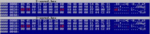
Here is the output when this script is ran against the full sample set I have (a question mark means that the value is changing and this script does the comparison against nibbles):
04 ?? ?? ?? ?? ?? 2? 8? ?? ?? 00 00 ?? 0? ?? ?? 06 0A 00 21 00 00 00 00 00 00 00 90 ?1 ?? ?? ?2 ?? ?? ?? ?? 0? 00 ?? ?? ?? ?? ?? ?0 FF 00 ?? ?? ?? ?? 00 00 00 00 00 00 00 00 00 00 ?? ?? ?? ??
As expected the last four bytes are varying (it is supposed to be a checksum) and first 16 bytes are also varying (those are read-only zone that are set by the manufacturer at production time). The first byte is not varying but it is expected as it represents the chip manufacturer (here, 0x04 stands for NXP semiconductors).
In such kind of locks, apart from your room number (which might be encoded as a floor number and a room number) and the duration of your stay, you can expect to find a hotel identification code or building code. This is to prevent a key from one building to open another door in another building for very big hotels. In order to determine where this code is stored on those tags, we run again the script to compute the mask. But we only run it against the 16 tags I have dumped on the last hotel I was staying at. As they cover a bunch of rooms for different duration, the mask might reveal easily the hotel id:
04 ?? ?? ?? ?? ?? 2? 8? ?? ?? 00 00 ?? 0? ?? ?? 06 0A 00 21 00 00 00 00 00 00 00 90 E1 A5 71 ?2 ?? ?? ?? ?? 00 00 ?? ?? ?? ?? ?? 00 FF 00 00 3F 00 00 00 00 00 00 00 00 00 00 00 00 ?2 ?? ?2 ??
Bingo! Indeed, if you compare carefully the last two computed masks, there are 3 bytes that are now constant (offset 0x1C): 0xE1A571. That should be the identification code for the hotel/building.
As we obviously have two sections in that dump (header/footer and then the XORed block), we will first leverage our knowledge to guess the structure of the first section (header + footer).
First, let’s go back to a simple bin-diffing process like we did on the first post but against the card that I got reprogrammed (same hotel, same room but duration of the stay should lessen).
Here is a capture of vbindiff against two unXORed dumps:
Interestingly, only 3 bytes changed within the protected section but there is absolutely no difference in the header/footer part! Regarding the last four bytes that were supposed to be a checksum, it is either computed only against the header or it is not a checksum! As we already took the assumption that offset 0x20 encodes the room ID, the byte at offset 0x27 might be part of duration of the stay.
Let’s verify the second assumption about the XOR key by running vbindiff against the raw dumps:
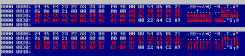
Damned! The XOR key is different too despite the header/footer being exactly the same. So it can’t be derived from it. My guess is now that it is just a sort of random key, computed at programming time, probably indicated at offset 0x1A, even though it might be bruteforced by the reader. But such attack would imply delay in accepting the key card so it doubt a bruteforce attack is involved here.
With those new findings, there does not seem to have any dependency between the two sections. We can then analyze them separately.
As I haven't found a more convenient way to do it, I'm using scapy to display the file structure I have guessed so far:
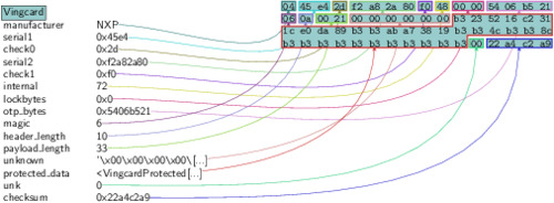
In the above picture, you can see that the protected_data is still encrypted. But if I ask scapy to create a graph out of that specific field, everything is automatically decrypted:

The Raw payload that it still present is just the remaining constant bytes of the protected_data. As we previously saw with the mask generated earlier, those bytes remain constant across the whole sample set, so I didn't bother dissecting them with scapy.
Please keep in mind that the field names above are still guesses and I can be wrong. Specially, I don't know the exact field length of hotel_id, key_id, duration and room_id.
This is all for this post because I won't have enough time right now to refine the cross-analysis over the 24 dumps I have. Should any of my readers come with better ideas or proofs that some of my guesses are wrong don't hesitate to let a comment or to send me an email. If you have dumps that you can share, please throw me an email too :)
For those who are interested, you can find the scapy layer I wrote to dissect the dumps on my usual Bitbucket repository. Here is a sample of how to use it (you must have the Vingcard.py file in your current working directory before launching Python):
$ python >>> from Vingcard import * WARNING: No route found for IPv6 destination :: (no default route?) >>> f=open("dump.hex", "rb") >>> p=Vingcard(f.read()) >>> f.close() >>> p.show()
One thing I didn’t mentioned in my previous article about Vingcard’s technology is that, in a full deployment, the individual locks communicate with a Zigbee gateway on each floor and those gateways are connected back to the reception, giving them a real-time view of what’s happening. Unfortunately, I doubt that hotels are going to buy the full package or that the reception will do something if the console shows something weird is happening.
Even though I am pretty sure that Zigbee antennas were deployed on the last hotel I was staying at (there was white dome antennas every 10 meters on every floors), it was abroad so I hadn’t brought my Api-mote board to play around with that signal. But if someone starts to analyze this signal, please, again, leave a comment below or send me an email!
0 notes
Text
Reversing H.Koenig wireless remote (part 3)
For those who want to read the whole story from the begining, here are Part 1 and Part 2.
I haven't talked about this project for a while but I was still working on it. So, what took me so long that I didn't write about it?
Well, as I told you in Part 1, my final goal is to be able to control the robot vacuum with a GoodFET and a transceiver. The robot relies on an A7105 transceiver which is not directly supported by the GoodFET project and I don't want to add support for it as I have already written code to support a Chipcon CC2500 transceiver that might be radio-compatible with the Avantcom one.
Knowing all the parameters we need by spying the configuration phase on the SPI bus from the remote control should have been enough to build another remote. But sometimes things don't go well!
First, let's talk about the good point. In the previous part, I made an assumption about the last byte of the packets being a kind of checksum and I was totally right about that! The algorithm is the easiest you can think of: sum all the bytes from the packet together and keep the least significant byte of the result as the checksum.
Now, let's go through the things that went wrong... Just relying on the code I wrote on the GoodFET project I wasn't able to send/receive any packet to/from the vacuum/remote. Debugging is not easy because we are talking about radio. It's not something you can see and a lot of things can disturb the transmission as I am not living in a Faraday cage. Not being 100% sure of my code, I decided to buy the Chipcon debugger along with a CC2511DK dongle to help me on that part.

I could have tried to use rfCat for that stuff but it is only compatible with dongles that handle frequency lower than 1 GHz.
Chipcon debugger is a small device that Texas Instrument SmartRF Studio software can handle directly. This way I know for sure the TX/RX are fine and all I have to care about is the RF configuration. The main drawback of such setup is that it only runs under Windows and you have to write packets in the GUI then click the send button. In other words, I won't be able to send 4 "Button pressed" packets followed by a "Button released" packet with good timings.
Here is a picture of the nice GUI that SmartRF Studio gives you:

Long story short of what happened:

The robot never issued a single beep to acknowledge the packets I was sending.
So, what can you do when easy options are out? Well, take the long path of course. And that involves slightly more expensive gears: SDR (Software Defined Radio). If you don't know what SDRs are, those are radio transceivers that are re-configurable: instead of doing things in the hardware, you just setup a local oscillator frequency and a bandwidth to listen to and it will provide samples to your computer. All the signal processing is then done using the computational power of your computer (filtering, demodulating, etc.). Sorry for those who are expecting lot of details on that topic but there's just too many things to say on that subject to fit within a couple of paragraphs. Just Google that and you will find a lot of documentation, tutorials and hacks on the Internet.
Fortunately, last year, I was one of the proud backers of the bladeRF project on Kickstarter so I already had everything needed as this board is able to do both TX and RX at the same time. Its frequency operating range goes from 300 MHz to 3 GHz so we don't need extra electronics (an up-down converter).

For the software we will use Gnuradio 3.7 to do everything as it already provides all the required tools. For those who are not familiar with this project, Gnuradio is a very powerful tool to deal with SDR. It basically provides you simple blocks that you can arrange to do almost everything you want (yes, just like Lego blocks). Even if it is an awesome tool, there is black magic inside. Learning how to use it by yourself might not be easy despite the tutorials that you can find on the Internet. Best option at the moment is probably to wait for Michael Ossmann to release his SDR video tutorials related to his HackRF Kickstarter project or find someone that already knows how to use it (hackerspace, etc.). In my case, I was lucky enough to have worked with Arnaud, one of my team mate, that is what I am not: an electronician that learned signal processing and all that stuff. I learned a lot from him, thanks man!
The first thing to do in order to fine tune all the radio parameters is always to try to receive correctly a packet. So I built the following Gnuradio flow graph in that purpose:

Let's quickly go through the blocks I used:
osmocom Source is the SDR reception channel. Frequency is set to 2.45 GHz with a sampling rate of 8 Msps
Simple squelch simply provides a reception threshold. If the signal is lower than threshold, this block simply "mutes" its output. This is an easy way to get rid of the noise.
Low pass filter is used to cleanup the signal and reduce the amount of samples (saving computational power). From the chip setup phase, we know that the bandwidth is 500 kHz so we put this as the cutoff frequency. A decimation of 8 will produce 1 Msps on the output which is enough.
Quadrature demod is the block that will demodulate the FSK signal. Gain parameter is set to a default formula that will rely on a variable called fsk_deviation_hz. So we just have to add one block for this variable and set its value to 186000
Rational Resampler is here to reduce once more the samplerate to fit our parameters
Threshold will convert our signal into 0 and 1 (it just acts as a hysteresis comparator).
Multiply const and Add const blocks just do what their name suggest. This is a simple trick to convert the output of the Threshold block ("0" and "1") into something suitable for the next block (ie. positive and negative values, "-1" and "1")
Binary slicer will convert our float values into bytes
Correlate Access Code is a pattern detector. Just give it a pattern (max. 64 bits) and it will modify your stream to mark this specific pattern. In this case, I set the access code to be the remote ID (0x58 0x52 0xD2 0x41). Threshold value is the amount of incorrect bits that can occur within the pattern.
UChar to Float just converts data back to float because the scope cannot display bytes
Scope Sink will provide us a neat scope to check our signal
Running the graph will pop up a GUI windows with all the controls and here is a packet that I successfully grabbed:
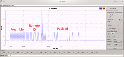
I added text to the capture in order to spot the three parts of the packet. Red lines are for the trigger configuration.
The packet starts on the left with the preamble immediately followed by the remote ID. The end of the remote ID code is tagged by the correlate access code block and this is the spike you can see on the capture. The spike value can be either 2 or 3, depending on the bit value it had altered and I used that property to trigger the scope and display a packet. The rest of the bit stream encodes the 8-byte packet that I already described in the previous part.
That's looks promising! Reception is good! Next step is to modify this graph by adding a custom block (that I still have to write) to create packets out of this bitstream. The flow graph will then send those packets to a local UDP socket instead of the scope sink, so that we can process them easily. This will also help us for the next step: transmitting!
But that's going to be detailed on the next part :)
0 notes
Text
Quick non-technical update
This is one of my shortest blog post indeed.
While reading the slides of NCCGroup at BlackHat Asia 2014, the picture of the Facedancer21 looked pretty familiar to me. And it was not a coincidence because this was actually the picture I took last year of my own Facedancer to illustrate one of my blog post :-)
That gave me the following information:
They read my blog, which is great :-)
They seemed to like my pictures, which is also great!
They bothered giving credits for cliparts but not for my picture... :-(
I frankly don't mind if my work is re-used. It's pretty much the opposite in fact: I'm quite proud when my work holds someone's attention. Otherwise, what is the point of publicly publishing it, right? But I just expect people to behave "neighborly" like Travis Goodspeed may have said.
As I was faulty not putting a license indicator on my blog, starting from now, you can see the nice Creative Commons logo on the right side. It is a quite permissive license I think, still letting people do what they want. For people, organisation, etc. that need specific stuff under another license for any reason, feel free to ask me. Most of the time, it will be granted.
Edit (2014-03-29):
They contacted me and updated their slides. Very nice guys and very reactive. Hats off!
0 notes
Text
RFID, when the manufacturer matters...
Nowadays we can find RFID technology almost everywhere: in supermarkets (anti-theft), in assembly lines (identify & track items), in highways (tolls), in public transportation, in your passport and your credit card and it is also used by many companies and by hotels for access management.
This post is about the latter. Indeed, during my trips, should it be for business or for holidays, I have stayed in many hotels. Some of them were still using good old keys like you do at home, most of them still use magnetic cards and some were relying on RFID cards to give you access to your room. Unfortunately, the security level of such RFID access management highly depends on the manufacturer as we will see.
First, let's begin with the tools I use. I started messing with RFID more than a year ago and today, I mostly rely on two tools:

A proxmark3 which is a really awesome tool, able to deal with low frequency tags (120-135 kHz) and high frequency tags (13.56 MHz) but it's pretty expensive, you have to handle external antennas and it relies on a dedicated client

An OpenPCD 2 which only deals with a limited amount of high frequency tags but it's opensource, credit card sized, and natively supported with libnfc and related tools.
So, basically, proxmark3 is useful when you are at home or at the office and it is mandatory for specific RFID technologies but usually, when I travel, I try to keep my hand-luggage as light as possible. That's why I mostly rely on my Android tablet and why I avoid carrying specific cables (proxmark uses one of those between the main PCB and the antenna).
To still be able to mess with RFID/NFC technologies I might encounter while travelling, I cross-compiled a recent version of libnfc and mfoc to reasily crack Mifare Classic keys. There is also a tool called mfcuk but unfortunately this one had never worked so far... It only displays timing errors and never finishes. By googling, I don't seem to be the only one encountering issues with it...
I won't go into details about all kind of RFID tags that you might encounter but I am going to detail some of the NXP tags inside their Mifare family, which still seems the most popular ones for 13.56 MHz tags:
Mifare Ultralight (64 bytes memory divided into 16 pages of 4 bytes, almost no protection)
Mifare Classic (1KB or 4KB memory, divided into blocks, with r/w protection relying on two 6 bytes keys and custom cryptography algorithm called Crypto1 which is broken)
Mifare Plus (2KB or 4KB memory, adds AES-128 cipher to the Mifare Classic tag)
Mifare DESfire (2KB, 4KB or 8KB and uses DES cipher)
All those cards have a read-only area at the beginning of the memory that has been set by the manufacturer. More details about NXP Mifare family here.
OK, enough "theory" for now :)
So far, I encountered two manufacturers of RFID key systems dedicated to hotels:
VingCard Elsafe, a Norwegian company
Kaba Ilco, a Swiss or German company
VingCard seems to be quite an old player in hotel locks as I have already seen cards like those:

They might ring a bell for those of my readers who began working with computers when punch cards were the only way to interface with a computer ;-) But let's go back to recent wireless technologies.
As far as I can tell, VingCard uses Mifare Ultralight tags for their locks. If you have read carefully the last paragraphs, you may rememer that this particular kind of token lacks security measures: anybody can freely read the content (64 bytes of data).
On the other side, Kaba is using Mifare Classic 1K cards for the customer's keys and Mifare Classic 4K for manager's keys (sort of master key + required to program customer's keys). At least, on those, we found a bit of security. Unfortunately, crypto1, NXP's cipher algorithm, is broken and you can recover all the keys in a matter of minutes (or something only a few seconds) with the tools I mentionned (mfoc / mfcuk or proxmark3).
My first goal to understand how those keys work was to dump them, several times, entering the room between dumping attempts just to check if it has a counter stored in it. At least, I expect to find, maybe encoded in a weird way:
the room number
start date of my stay
duration of the stay
Also, to get extra dumps, I went back at the reception desk, asking them to program again my key because it was not working anymore or even asking them a new key because I seemed to have lost the first one (of course, I have given back both keys at checkout to avoid extra charges). Another thing to try when you have friends or family in the same hotel is to dump their keys too, specially if they are on the rooms next to yours (or at least on the same floor in case the floor is also encoded in the card). This way I was able bindiff the dumps and try to find useful stuff.
Let's begin with VingCard. Here is the result while running vbindiff agains two different keys encoded for the same room:
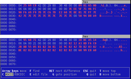
That's a lot of red! The first few bytes have to be different because it is the "unique ID" of the tag. But if we take a closer look at those dumps, we can see a pattern: one byte is repeated a lot on each dump in the red part. This value might be used to XOR the useful content. And the 4 final bytes might be a checksum value. Note also the constant 0x21 value across those dump at offset 0x13. Surprisingly, it matches the length of the big red block...
Let's try again vbindiff after XORing the 33-bytes red memory block...

That's definitely better! But we will have to found out later how this byte is computed... The next assumption we can take is for the three bytes located at 0x1F-0x21: on this particular hotel, I was given two room keys at once. So it might be the "key number" or something related.
Next step is to compare keys encoded for two different rooms within the same hotel (after XORing their respective blocks of course):
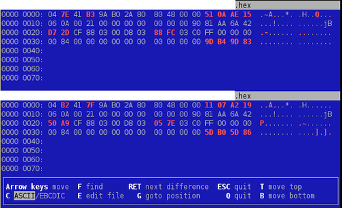
Bingo! We still have the same differences we have seen. Appart from that, only two bytes have changed between those cards. Those have to be the room number (or at least some sort of lock ID number).
Also, if you look carefully at the last two screenshots, you may notify that the byte at offset 0x1F only has 2 possible values so far: 0x42 or 0x82.
As it was a short stay (1 night), I wasn't able to go deeper on those (trying to figure out the duration encoding and things like that). But remember, we still have to find how the XOR key is computed and what kind of checksum is used.
Well, for that part, I may disappoint you but no luck so far :( If any of my readers have a clue, please leave it in the comments and I will test it against all the dumps I have.
At the beginning I was talking about comparing the badly designed VingCard RFID system against Kaba Ilco's one.
Long story short, by applying the exact same method, I can tell you that this one seems pretty good in several points:
Mifare Classic keys (A and B) seem to be derived from the UID of the tag but despite a whole bunch of dumps, I wasn't able to find an obvious algorithm
While bindiff-ing two dumps, I always ended up with two completely different 16-bytes blocks even after having my key reprogrammed. Marketing brochures states that they use cryptography so my guess would be that this is an encrypted block, depending on the Mifare Classic 4K tag (the Manager key) that has been used to program it. Moreover, the brochure also states that the cipher key is renew every 30 days.
Going further on Kaba Ilco's system would require to use the proxmark3 for passively sniffing RFID exchanges between the tag and the lock.
As a conclusion, we can say that every manufacturer states that his system is secure but one should really ensure that it actually is, either by auditing the system himself or by relying on a third-party actor that can do that.
0 notes
Text
Dumping Z-Wave device firmware
I know I was a bit quiet during the past monthes. This is due to too many projects to handle simultaneously...
In the previous weeks, I had to work on Z-Wave devices and that lead me to dump the firmware of those devices. Consequently, I used my favorite GoodFET to acheive this goal :-)
Code is now available on the GoodFET's project repository. Be aware that you will need to update the firmware of your GoodFET device before using it because the Z-Wave chip requires specific timing and bit banging.
More details on that work are available on my employer's blog as, this time, this was not a spare time project :)
0 notes
Text
A journey in script-kiddie-land and kernel-land
Yes, I know what some of you may think: will we finally get the third and last part about the robot vaccum? You will. But trust me, I don't have a lot of spare time and debugging the radio stuff is not the funniest part nor the easiest one!
But let's come back to our subject. Reading some (all?) of my posts here, you may know what a GoodFET is. But have you heard about its little brother, the FaceDancer?

It is basically a GoodFET + an USB controller on the same PCB. It runs the same firmware as a GoodFET and it's purpose is to be able to emulate any USB device that you can imagine. Under Linux, it is pretty easy to mess with USB peripherals by relying on libusb. But with an USB host controller, you cannot emulate peripherals at all. And that's precisely where the FaceDancer comes in handy.
What can you do with that? Well, you can circumvent your company USB port policy by emulating a keyboard, just like shown with a teensy on Hackaday a while ago. Or you can capture USB firmware like demonstrated by the awesome Travis Goodspeed himself. You can even fingerprint the operating system by the way it is enumerating and reading an emulated USB mass storage device or do some bad ass anti-forensics stuff too, just like shown in 29C3 by Travis again.
Of course, you can just try to fuzz the USB protocol and try to find 0days on you preferred operating system. And guess what? That's exactly what we are going to do here!
But the USB protocol is pretty tough. Without going into the details, a device must expose a device descriptor that exposes one or more configurations, on which you get several interfaces, each one using endpoints (usually two) to be addressed and endpoints can be of 4 types (control, isochronous, interrupt or bulk)... So writing a fuzzer, whether it is in Python or not, is just not straightforward.
Fortunately, NCC Group did a real great job and published less than two months ago a very neat tool called umap that is designed specially for the FaceDancer to be able to emulate devices, fuzz USB stacks and even fingerprint an operating system. The latter function is not very accurate though as my Ubuntu was shown as ChromeOS. But still, imagine what an attacker can do if he finds several exploits through the USB stack and if he can actually fingerprint the operating system in an accurate way by relying on the USB stack too (hint: think about reliability).
The tool is fairly easy to use (on my computer, the FaceDancer comes up as /dev/ttyUSB3):
# Finds devices supported by the OS $ python3 umap.py -P /dev/ttyUSB3 -i # Fuzz a HID device class $ python3 umap.py -P /dev/ttyUSB3 -f 03:00:00:C # Try to identify the operating system $ python3 umap.py -P /dev/ttyUSB3 -O # Run a single fuzz test case $ python3 umap.py -P /dev/ttyUSB3 -s 03:00:00:C:16
So, as I already have a FaceDancer for almost a year and as I don't have to write my own fuzzer from scratch, I decided that it could be fun to let that tool run against a fully patched and up-to-date Windows 8.1 64bits, just like a script-kiddie can do. And yes, sadly, you can get a BSOD by just running a public tool against it...

But, as we are going to see through this post, a blue screen does not necessarily mean that you have an 0day. At that moment, you only caught a bug.
The first thing when dealing with kernel bugs is to configure the victim to not just reboot after a BSOD but also generate a kernel memory dump that you can grab and analyse. Once done, trigger the bug, let the host reboot and grab your MEMORY.DMP file.
Once you've got your memory dump, the tool you need is WinDBG. It is not the sexiest debugger ever, nor it is the funniest or most intuitive to use (specially when it comes to scripting) but that's still the one you need for that stuff :-)
First of all, configure your kernel symbol path otherwise you are working for nothing and then, simply load your file into the debugger (File > Open crash dump).
From this point, I will demonstrate the HID device test case number 16 called Report_Usage_Page_Logic_error2 (not the enumeration ones) provided by umap. Why this particular one? Well because it made the operating system crash from Windows XP to Windows 8.1 whether it was a 32bit version or a 64bit one :-)
WinDBG will tell you directly what caused the crash.

On the screen capture, you can see that WinDBG tells you that the crash, a bugcheck 0x7E, occurred in HIDPARSE.SYS which is obviously the drivers that deals with the USB keyboard we were emulating and fuzzing.
The debugger is also kind enough to guide you and make you launch its extension command "!analyze" (in WinBDG, every command that starts with an exclamation mark is implemented in an extension DLL). This command will give you details on what precisely happened.

Here we can see what type of error we encountered: a NULL pointer is deferenced.

And on this final screen, the debugger shows you the call-stack and the faulty function: HidP_ParseCollections in HIDPARSE.SYS file.
By digging a bit further, you can tell that a function is called to create a structure. As our emulated device sends invalid stuff, the function fails and returns a NULL pointer that the caller does not check and BANG! Classic input validation failure.
Unfortunately, this kind of bug is not going to lead into code execution and will stay a simple and annoying denial of service. It was somehow predictable as the NCC Group may already have run their own tool against Windows to check for 0day themselves and report them to the MSRC.
But like I said, I was merely using the tool out of the box. Even though it comes with a lot of emulated devices and test cases, there is still a huge amount of work around that tool that can be done. For example, within a device class (e.g. a printer), depending on the vendor ID and product ID you are emulating, you may hit different drivers and some of them may be more buggy than others (specially third party drivers). In addition to that, all the device classes are not implemented yet and the OS fingerprinting function may be improved.
I hope that this post made you interested in USB security assessment and kernel debugging. If you want to get more information about how to analyse a Windows kernel memory dump with WinBDG you can start by reading this page and I also warmly encourage you to keep an eye at my co-worker's blog and/or following him on Twitter. He really is an awesome guy :-)
Should you find any vulnerability, don't forget to report it the Microsoft Security Response Center for Windows related ones or the appropriate contact for other vendors.
I also encourage you to contribute to umap tool to support the work that NCC Group did. That's the best way to thank them for making it opensource software.
Finally, to conclude this post, I would like to thank another co-worker, F4b, that did the analysis of every single memory dump that umap generated. Even though we weren't lucky this time, he is a scary dude when it comes to reverse engineering and/or vulnerability exploitation :-)
1 note
·
View note
Text
Firmware extraction and reconstruction
Recently I had to extract a firmware from an I2C EEPROM.
Although I am pretty used to SPI EEPROM on embedded equipments, seeing an I2C bus seemed pretty unusual to me.
As you may have noticed from my previous posts, I make heavily use of my GoodFET. It is a very handy tool and although I also have a BusPirate v4, I prefer Travis's tool. Unfortunately, I2C protocol is not compiled by default on the firmware, the tools are marked as "untested" on the website and the pinout is not documented on the website. That's a lot of things to find out :-)
The pinout issue will be quite easy to solve as all we have to do is look at the firmware source code! In the file "firmware/apps/i2c/i2c.c" we can read the following:
#define SDA TDI #define SCL TDO
Our next step is to compile a new firmware, including i2c protocol, by running the following commands:
$ board=goodfet41 CONFIG_i2c=y make $ board=goodfet41 make reinstall
So far, so good. Finally, we have to run the client and get our EEPROM content, right? I2C requires and address on the bus. It is usually a 7 bit address that is then shifted left once to add a R/W bit at the end.
By having a look at the EEPROM datasheet, the basic address is 0x50.
$ goodfet.i2ceeprom dump 0x50 output.bin Dumping 256 bytes from device 0x50 starting at 0x00 to file: output.bin. Traceback (most recent call last): File "/usr/local/bin/goodfet.i2ceeprom", line 50, in <module> data=client.I2Ctrans(count, [devadr, start]) File "/home/jm/workspace/goodfet/trunk/client/GoodFETI2C.py", line 32, in I2Ctrans return self.writecmd(0x02,0x02,len(data)+1,[readcount]+data) File "/home/jm/workspace/goodfet/trunk/client/GoodFET.py", line 438, in writecmd data[i]=chr(data[i]); ValueError: chr() arg not in range(256)
Doh! The client is not working at all :-(
By adding some debug lines, it appears that the script is sending 0x100 (the length to be read, aka 'readcount' variable) but then, the script tries to convert it into a char.
Obviously I don't want to read the EEPROM by chunks of 128 bytes saved into individual files and then concatenate everything back. So I spent some time reading the datasheet.
To talk to the EEPROM, you have to write at least 3 bytes:
Address of the component on the bus
A 2 bytes address from which you want to read or write
Unfortunately, the client is dealing with a single byte address.
Therefore, I patched the client to mimic the behavior of the similar SPI client that dumps EEPROM:
Reading/writing addresses are now 2 bytes long
The client reads the EEPROM by chunks of 128 bytes and thus can accept arbitrary length.
In addition to those changes, I notified that it would be great to have an I2C bus scanning command, just like the macro provided by BusPirate. Hence I am currently adding it to the client.
As soon as the code has been tested enough, I will push it to the main repository.
Being careful when I dump a firmware directly from a soldered component, I always do it twice to check that the files are identical. And guess what? They were not!
To tackle that problem, I simply ran vbindiff and found the following:

It seems I have read issues at some chunks. I don't know if it is due to the MCU trying to access the EEPROM simultaneously or a firmware error on the GoodFET but I didn't want to spend a lot of time investigating that issue.
Therefore, I decided to dump multiple times the EEPROM, assuming that, statistically, the read errors won't be at the same offset each time. To finally get the full firmware, all I had to do is run a small tool that takes all the dumped files in input and select for each byte the value that is the most frequent one!
I was a bit surprised but I expected such tool to already exist. As a google search wasn't successful, I wrote the tool and it worked just like expected!
The tool is available in my Bitbucket account and is called "firmware-reconstruct.py". It takes one parameter for the output file name and all other parameters are considered as input candidates. Files are read by chunks to prevent memory exhaustion issues and then every bytes are compared to choose the right one for the output. The tools also prints a warning if two candidates have the same occurrence frequency, letting you know that you may need another dump.
Any feedback is welcome and I hope this tool will be useful to someone else :-)
0 notes