
Don't wanna be here? Send us removal request.
Statistics
We looked inside some of the posts by js-knlhydraulic and here's what we found interesting.
Average Info
Notes Per Post
1
Likes Per Post
1
Reblog Per Post
0
Reply Per Post
0
Time Between Posts
9 days
Number of Posts By Type
Photo
1
Text
14
Last Seen Tumblr Blogs


Fun Fact
Tumblr.com is the 103rd most visited website in the world.
Photo
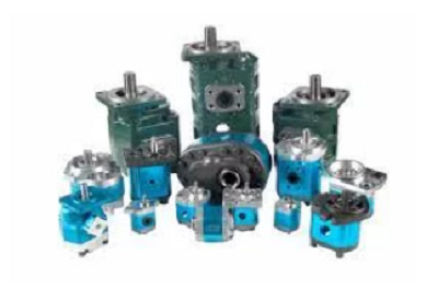
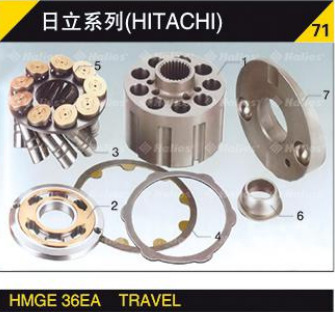
A micro gear pump is a small pump that uses a pinion-driven internal gear system. These pumps are ideal for applications requiring high system or differential pressure. They also do not require a dynamic seal, which ensures leak-free operation. Their solid shaft support provides accurate meshing of gears, ensuring smooth operation and high metering accuracy. These pumps have a long service life. They can handle a wide range of pressures.
Internal gear pumps
Internal gear pumps are positive displacement pumps with rotating cogs or gears that compress liquid to move it through the pump. The fluid enters the pump through the inlet, where it is contained by the gear teeth and is transferred to the outlet. The pump produces a smooth, pulse-free flow.
Internal gear pumps are designed with precision tolerances to ensure smooth operation. They can handle pressures up to 3,000 psi and 200 bar. However, they are not well suited to high-temperature or abrasive fluids, and their internal clearances increase with increasing viscosity. Additionally, internal wear can significantly reduce pump efficiency until the point of failure.
The crescent-shaped seal between the gears prevents the fluid from leaking into the pump and is important for high-viscosity applications. Internal gear pumps are also self-priming and dry-lifting, so that they can run without needing lubrication. However, they should not be run on dry-lift for long periods of time. Gear pumps have a range of applications and can be used to load or unload vessels.
0 notes
Text
Electrical and installation of pneumatic directional control valve

1 Notes related to electrical
(1) Make sure that the electrical circuit connected to the pneumatic directional control valve does not have poor contact. If the coil remains energized for a long time, it will inevitably cause heat, and after the insulation deteriorates, there will be a lot of energy loss. In this case, you can consider choosing an electromagnetically controlled pneumatic directional valve with a memory function to make the coil energized. Working time shorten.
(2) Only after confirming that the electromagnetically controlled directional valve is powered off, the manual button is allowed to reverse the direction of the directional valve. After using the manual button to switch the solenoid valve, it is not possible to energize the solenoid-controlled directional valve, especially the direct-acting solenoid valve, otherwise, it is easy to burn the valve.
(3) Ensure that the voltage used to supply the electromagnetically controlled directional valve must be within the allowable voltage fluctuation range of the valve before it can work.
(4) For the pilot solenoid directional valve, the power-on or power-off time of the pulse electrical signal should be greater than 0.1s, to avoid the malfunction of the main valve due to the short power-on or power-off time and it is too late to be completely switched. If the time of the pulse electrical signal is too short, the pulse electrical signal can be maintained for a sufficient time by setting the time relay.
(5) If the system requires long-term continuous power-on, the selected solenoid valve should have the function of long-term power-on, or choose to use a low-power solenoid valve or a solenoid valve with a power-saving circuit.
(6) Because the solenoid valve is generally installed in the control cabinet, when the solenoid valve may continue to be energized for a long time, the problems of maintaining good ventilation and easy heat dissipation of the control cabinet must be considered to ensure that the temperature of the solenoid valve is always kept within the allowable temperature fluctuation range of the solenoid valve.
(7) When the switching element and the resistance-capacitance element are required to be used in parallel, there will be a leakage current through the resistance-capacitance element, and this leakage current will generate a leakage voltage at both ends of the electromagnetic coil. If the leakage voltage is too large, the electromagnet will always be energized but cannot be powered off. In this case, the leakage resistance can be connected to ensure safety. The allowable voltage through the solenoid coil that ensures that the moving iron core can be reset is called the reset voltage. If the reset voltage of the solenoid valve is less than the leakage voltage, the moving iron core cannot be reset. Therefore, to reset the moving iron core, the voltage used must be greater than the drain voltage.
(8) When wiring a solenoid valve with an overvoltage protection circuit for DC specifications, first confirm whether it has polarity. When it is found that there is a polarity, it should be considered that if the polarity is wrongly connected, the electromagnetic coil will burn quickly because there is no built-in diode for polarity protection; if there is a polarity protection diode, even if the polarity is wrongly connected, the valve just doesn't switch.
2 Notes on the installation of pneumatic directional valve
(1) Generally speaking, there are not too many requirements for the installation of the electromagnetically controlled directional valve, but when installing the three-position spool valve and the double electric control spool valve, pay attention to keeping it level. Pay attention to the installation direction to prevent the intrusion of water and dust. For example, the electromagnetic head or electromagnetic coil should not be installed downward to avoid the intrusion of condensed water. In an environment with vibration, the installation direction of the spool valve should be perpendicular to the vibration direction when installing the spool valve. If the vibration acceleration in the environment is too large, the solenoid valve cannot be used.
(2) There is a breathing hole at the control piston of the main valve, and the exhaust hole of the pilot valve this breathing hole must not be blocked or the exhaust is not smooth.
(3) The reversing valve should be installed as close as possible to the cylinder, which can not only reduce air consumption but also speed up the response speed.
Jiangsu Kerai Hydraulic Pump Co., Ltd. is a high-end equipment manufacturer specializing in the production of high-pressure plunger pumps, motors, hydraulic reducers, and spare parts. We have
pneumatic directional control valves for sale.
If you have your own opinions on the hydraulic motor, please contact Jiangsu Kerai Hydraulic Pump Co, Ltd.
Related news of hydraulic components
Analysis of common faults and repair methods of relief valve
Working principle and precautions of hydraulic pumps
Analysis of common faults and repair methods of reversing valves
#pneumatic directional control valve#pneumatic directional control valvesfor sale#electromagnetically controlled directional valve
0 notes
Text
Medium and working environment of pneumatic directional control valve
Pay attention to the relevant medium and working environment when using the pneumatic directional control valve
1 Air
The compressed air used in the system should be kept clean enough. For this reason, an air filter device of no more than 5 μm is often installed upstream of the reversing valve. When the air compressor system produces a lot of carbon powder, the carbon powder will adhere to the valve body of the directional valve, which will inevitably lead to the bad action of the valve. If necessary, an oil powder separator can be installed in the pipeline to separate oil powder, to reduce the harm caused by inferior oil mist to the entire pneumatic system.
2 Condensate
The condensed water should be removed in time to avoid poor component action or poor responsiveness. An automatic drain filter should be used in places where management is inconvenient. If the temperature of the environment and medium is lower than 5°C, a necessary dryer should be set up to ensure that the air provided for the system is sufficiently dry. Generally speaking, solenoid valves can be used in In a low-temperature environment (eg -10°C).
3 Lubricating
Some components have pre-lubricated characteristics before they are used, so such components can be used without oil. However, components without pre-lubrication characteristics should use appropriate lubricating measures as specified. Components that do not need oiling can also be lubricated. However, once such components are used like lubricating components, they must not stop oiling, otherwise, it is very easy to Lead to bad action of the pneumatic valve. When some lubricating oils work below 0 °C, their viscosity will increase significantly, which may lead to unexpected failures, and more attention should be paid.
4 Bad environment
It is necessary to avoid installing the valve in adverse environments, such as places where there are corrosive gases or chemical solutions and water vapor in the environment, and where the ambient temperature is higher than 60 °C. When it is determined that the pneumatic directional valve is used in an environment with water droplets or oil droplets, a drip-proof directional valve should be selected; when there is a lot of dust in the use environment, it is necessary to consider using a pneumatic directional control valve with dust-proof function as much as possible; When the valve is working, when there may be sparks splashing around (such as welding and other similar work), be sure to install a protective cover to prevent sparks from splashing on the directional valve for safety protection; when the environment is inflammable and explosive When it is dangerous or hidden, an explosion-proof pneumatic directional control valve should be used; because the pneumatic transmission system is noisy, a suitable muffler should be installed at the exhaust port of the system, which can not only reduce the discharge of oil mist but also reduce the noise. However, when the muffler is installed at the exhaust port, the back pressure will rise, so at this time, it is necessary to consider whether it affects the movement speed of the cylinder.
5 Organic solvents
If there is an organic solvent in the environment, pay attention to the problem that the organic solvent will damage the resin label and so on.
6 Ozone
If there is ozone, it may cause rubber cracks, air leakage, or poor operation on pneumatic components such as directional valves, etc., and may cause adjustment of adjustable components such as pressure-reducing valves and speed control valves.
Jiangsu Kerai Hydraulic Pump Co., Ltd. is a high-end equipment manufacturer specializing in the production of high-pressure plunger pumps, motors, hydraulic reducers, and spare parts.
If you have your own opinions on the hydraulic motor, please contact Jiangsu Kerai Hydraulic Pump Co, Ltd. We have pneumatic directional control valves for sale.
Related news of hydraulic components
Analysis of common faults and repair methods of relief valve
Working principle and precautions of hydraulic pumps
Analysis of common faults and repair methods of reversing valves
0 notes
Text
Precautions for the use of pneumatic directional control valves

Pneumatic transmission is a transmission method that is very similar to hydraulic transmission in the working principle. Because its working medium has many advantages such as clean and cheap, convenient access and handling, and low resistance to flow, the application of pneumatic transmission technology has become more and more extensive.
With the in-depth application of the pneumatic system, we have learned more about this fluid transmission technology, and also summed up some precautions in the use and maintenance of pneumatic directional control valves, hoping to provide a reference.
1 Requirement for connecting piping
(1) The hard pipe used for connection should be galvanized steel pipe with an anti-rust function. The length of the hose connected between the cylinder and the valve should be kept as short as possible, and the installation should be designed to avoid compromise.
(2) Before connecting the piping, clean up the debris, oil, and dust of various materials in the pipe. It is best to blow it off because when the piping is connected, there will be various debris (such as hidden in the pipe threads) and debris (such as sealing material) into the valve body. When sealing with sealing tape, a part of the length of the threaded end should be left unwrapped with the sealing tape. This length is about 1.5~2 threads, and the sealing tape should be wound in a clockwise direction.
(3) When installing the pipe joint on the reversing valve, care must be taken to ensure that the size of the pipe joint does not interfere with each other. The design of the piping system should take into account the easy disassembly, installation, and disassembly of the reversing valve in case of failure, that is, space for inspection, maintenance, and replacement of new valves should be reserved.
(4) Refer to the relevant information for the torque when installing the piping. The torque should not be too large to cause it to be over-tightened, otherwise, cracks will easily occur at the interface.
2 Other Notes
(1) When the directional valve used is a mechanical control type, it is necessary to pay attention to prevent overload, and not have any action beyond the limit position.
(2) If the electromagnetic directional valve is an internal pilot type, it should be noted that the inlet should not be throttled to prevent the occurrence of malfunction due to too large a pressure drop when the directional valve is reversed.
(3) When using a superimposed valve, pay attention to the back pressure that may cause some actuators to malfunction, especially when using a three-position mid-release pneumatic reversing valve and driving a single-acting cylinder. In this regard, if you are concerned about the possibility of malfunction, you can use a separate exhaust manifold, or use a separate exhaust baffle assembly to prevent adverse effects caused by back pressure.
(4) Maintenance and inspection are inevitably required during the use of the pneumatic system, so when using the pneumatic directional valve, it is necessary to fully consider whether the system can release residual pressure, especially the use of three-position middle-sealed reversing valves or aborted reversing valves. When reversing the valve, it must be considered that there is a way to release the residual pressure energy between the cylinder and the reversing valve.
(5) For the place used for blowing air, consider using a direct-acting electromagnetic directional valve or an external pilot-operated electromagnetic directional valve.
Jiangsu Kerai Hydraulic Pump Co., Ltd. is a high-end equipment manufacturer specializing in the production of high-pressure plunger pumps, motors, hydraulic reducers, and spare parts.
If you have your own opinions on the hydraulic motor, please contact Jiangsu Kerai Hydraulic Pump Co, Ltd.
Related news of hydraulic components
Common types and application analysis of hydraulic control valve
The development trend of the hydraulic industry in the future
Application of hydraulic technology
0 notes
Text
Analysis of common faults and repair methods of flow valves

For the hydraulic system, all kinds of pressure control valves show high similarity in structure and operation principle.
In the process of applying the flow control valve, the flow control valve can realize the centralized control of the flow problem of the hydraulic system, and can also complete the control and management of the operating speed of the actuator. Combined with experience, the flow control valve needs to meet certain pressure conditions to achieve the desired effect. During use, the hydraulic flow is controlled by adjusting the size of the orifice.
Unlike other hydraulic control valve types, flow valves fail more frequently during operation. The main reason is that the size of the orifice is relatively small, the cleanliness of the hydraulic oil is relatively strict, and the tightness of the hydraulic system must be guaranteed during use to ensure the quality of the application. However, it should be noted that in the process of adjusting the handle, the flow rate of the relief valve port is difficult to change, so the operating speed of the actuator cannot be adjusted in time.
Common flow valve failure problems and repair methods are as follows:
1 When there are burrs or oil contaminants in the throttle spool, it will directly cause the spool to be stuck. At this time, the operator should clean up the burr of the valve core to ensure the running performance of the throttle valve core; or replace the hydraulic oil to ensure the cleanliness of the throttle valve core.
2. The tolerance of the valve core and the valve body hole exceeds the limit value, which is easy to cause the throttle valve adjustment failure phenomenon. At this time, the operator needs to grind the valve hole facility in time. If necessary, reconfigure the spool.
3. If the equipment is not used for a long time, it will directly cause the valve core to rust. At this time, the operator should clean the valve core in time and reuse it after cleaning.
4. The hydraulic system flow valve needs to adjust the flow valve handle based on pressure relief, which needs to be dealt with according to the actual situation, as follows:
①The flow is not stable enough.
The oil may be used without strict filtration treatment, and impurities may accumulate in the oil, which will affect the flow area. Given this situation, it is recommended that the operator strengthen the oil filtration treatment to enhance the cleanliness of the oil.
②The oil temperature rises.
There may be pressure loss when the oil passes through the throttling gap, which will directly cause the oil temperature to rise under long-term action. When such problems occur, it is easy to precipitate impurities such as colloids and asphalt during the oil deterioration process. It is recommended that the operator clean the orifice in time.
③Leakage
Excessive internal and external leakage of the flow valve will lead to unstable flow, resulting in the unpredictable pressure feedback effect. In addition, the reverse connection of the oil port and the lack of pressure compensation feedback of the flow valve will cause the wrong spring installation or the leakage of the pressure-reducing valve.
In response to such problems, operators should take safe and reliable measures to check for leaks. During the inspection process, the operator should remove the screw plug at the end of the valve, pull out the pressure-reducing valve core, remove the burrs in time, and do a good job of cleaning. On this basis, the operator should do a good job of precision inspection. For the missing installation problem, the operator should re-install in time. In addition, the operator can replace the treatment for wrong installation or damage.
Jiangsu Kerai Hydraulic Pump Co., Ltd. is a high-end equipment manufacturer specializing in the production of high-pressure plunger pumps, motors, hydraulic reducers, and spare parts.
If you have your own opinions on the hydraulic motor, please contact Jiangsu Kerai Hydraulic Pump Co, Ltd.
Related news of hydraulic components
The working principle and characteristics of gear pumps
Five major parts and its characteristics of hydraulic system
Five steps to take you to understand hydraulic parts
0 notes
Text
Analysis of common faults and repair methods of control valves

As an important component of the hydraulic system, the hydraulic control valve mainly controls and adjusts the oil flow direction, pressure, flow, and other parameters in the hydraulic system during the application process, so that the actuator and the driving mechanism can obtain the required rotational speed and torque during operation. reach a good operating condition.
Hydraulic control valves are easily affected by unstable factors in the application process, and may directly or indirectly experience operating failures. On-site staff still need to continuously troubleshoot and maintain and manage to ensure the stable operation of hydraulic control valves.
Inspection and Maintenance
1 According to the concept of refined management, implement the daily inspection and maintenance management work
To ensure that the hydraulic control valve is always in an efficient and stable operation state, maintenance personnel should pay more attention to the daily inspection and maintenance management of hydraulic control valves. During the daily inspection work, maintenance personnel should always observe whether hydraulic control valves are in a normal state. Once an abnormality is found, the cause should be identified and ruled out in time. At the same time, maintenance personnel should check and analyze the working pressure of the hydraulic system and the action of the actuator, and reasonably determine the working state of hydraulic control valves according to the analysis feedback results.
Before the hydraulic pump is officially started, maintenance personnel should check and analyze whether each hydraulic control valve is in an adjustable state and a standard state. It should be noted that during the daily maintenance and management, the maintenance personnel should focus on the cleanliness of the hydraulic control valve to avoid the entry of pollutants. To avoid the loosening of the hydraulic control valve during operation, the maintenance personnel should regularly check and tighten the connecting screws of the hydraulic control valve. In addition, maintenance personnel should regularly clean some important hydraulic control valves and replace seals regularly.
2 Enhance the sense of responsibility of maintenance personnel and ensure the safety of hydraulic control valve operation
To ensure the safe operation of the hydraulic control valve and the timely elimination of faults, maintenance personnel should be deeply aware of the importance of their job responsibilities, and actively combine the operating principles and operating procedures of the hydraulic control valve to timely check the hidden troubles that are prone to occur during the operation of the hydraulic control valve. According to the inspection results, a troubleshooting plan is proposed to effectively enhance the operational safety of the hydraulic control valve.
In addition, the management personnel of the production enterprise should carry out training activities regularly, so that each maintenance personnel can grasp the troubleshooting and repair measures of the hydraulic control valve in time to ensure safety of the hydraulic control valve.
In short, to ensure that the hydraulic control valve is always in an efficient and stable operating state, the field operators should strengthen the control and management of the operating state of the hydraulic control valve. Actively combine the experience to accurately identify and eliminate the failure of the management hydraulic control valve. On this basis, according to the concept of refined management, the hydraulic control valve troubleshooting plan and maintenance management measures are formulated to fundamentally strengthen the operational efficiency of the hydraulic control valve.
Jiangsu Kerai Hydraulic Pump Co., Ltd. is a high-end equipment manufacturer specializing in the production of high-pressure plunger pumps, motors, hydraulic reducers, and spare parts.
If you have your own opinions on the hydraulic motor, please contact Jiangsu Kerai Hydraulic Pump Co, Ltd.
Related news of hydraulic component
Operating principle of the hydraulic pump
Learn more about the accessories of hydraulic parts--hydraulic cylinders
Learn about hydraulic parts and hydraulic technology
#maintenance management of hydraulic control valves#stable operation of hydraulic control valves#hydraulic control valve
0 notes
Text
Analysis of common faults and repair methods of reversing valves
For the hydraulic system, all kinds of pressure control valves show high similarity in structure and operation principle.
During the use of the reversing valve, it is necessary to rely on the change of the position of the valve core relative to the valve body to control the direction of the liquid flow. In recent years, as the level of electronic technology continues to improve, the number of applications of advanced electronic directional valves has increased. Based on past experience, the solenoid coil of the solenoid directional valve is burnt, the AC electromagnet has noise, and the solenoid valve action fails, which can be regarded as common faults of the directional valve.
1 Solenoid valve solenoid coil burnt
The main reasons for the burning of the solenoid coil of the solenoid valve are that the ambient temperature of the solenoid coil is too high, corrosion and aging, and the viscosity of the system working oil is too high, and the workload of the solenoid valve coil is significantly increased. In addition, insufficient machining accuracy or pollution of the solenoid valve will also cause the above problems. Therefore, it is recommended that the operator stop using the electromagnetic directional valve and replace the electromagnetic coil in time.
2 AC electromagnets are noisy
In the application process of the electromagnetic directional valve, it is easy to be affected by uncertain factors, and the phenomenon of electromagnetic coil sound occurs. From an objective point of view, the main reasons for the above problems are the quality of the electromagnet, the presence of pollutants between the movable iron core and the fixed iron core, and the rupture of the copper short-circuit ring of the fixed iron core.
In response to the above problems, it is recommended that operators take measures to deal with the problems based on the performance and specific causes. The quality problem of the electromagnet can be solved by replacing the electromagnet components. For the contamination between the movable iron core and the fixed iron core, it should be removed in time. The fracture of the fixed iron core copper short-circuits ring, should be repaired in time. In addition, the long push rod will also cause AC electromagnet noise. It is recommended that the operator shorten the handling of the push rod facility in time.
3 Solenoid valve action failure
Whether the action of the electromagnetic reversing valve is accurate is often an important factor affecting the quality of the operation of the electromagnetic reversing valve. Combined with past experience, the electromagnetic directional valve is easily affected by factors such as suction and spring force during the activation process, and the action fails. In addition, the quality of the electromagnet is too poor or the lead wire is broken, which is easy to cause insufficient electromagnetic suction.
When the above problems occur, the operator should promptly find out the cause and take remedial measures to deal with it. If the machining accuracy of the valve body cannot be guaranteed, it is recommended that the operator disassemble the valve body facilities in time, conduct internal inspections, and replace the reversing valve and spring facilities in time.
Jiangsu Kerai Hydraulic Pump Co., Ltd. is a high-end equipment manufacturer specializing in the production of high-pressure plunger pumps, motors, hydraulic reducers, and spare parts.
If you have your own opinions on the hydraulic motor, please contact Jiangsu Kerai Hydraulic Pump Co, Ltd.
Related news of hydraulic components
Common types and application analysis of hydraulic control valve
The development trend of the hydraulic industry in the future
0 notes
Text
Analysis of common faults and repair methods of relief valve
For the hydraulic system, all kinds of pressure control valves show high similarity in structure and operation principle.
For the pressure relief valve in the hydraulic system, during the application process, the operation stability of the hydraulic system can be strictly controlled to achieve the protection state of the hydraulic system. Based on past experience, the relief valve can be refined into a direct-acting relief valve and pilot-operated relief valve according to the structural form and action principle. During the application process, you can refer to the following contents to complete the troubleshooting and management of the fault:
1 The pressure cannot be raised
When the operator tightens the screw or handle, the pressure cannot always be adjusted to the maximum value. The on-site operator should focus on whether the damping hole of the main spool is blocked and whether the pressure regulating spring of the pilot valve is broken. Combined with past experience, once the above problems occur, it may directly lead to the inability to increase the pressure of the relief valve.
In response to this problem, it is recommended that the on-site operator disassemble the overflow valve in time, locate the fault point and find the cause. In addition, if the direct leakage problem between the main valve and its valve seat is too large, or the direct leakage problem between the pilot valve and its valve seat is too large, it will cause the problem that the pressure cannot be adjusted successively.
2 A sudden increase or decrease in pressure
The sudden increase or decrease of the pressure will directly cause the operation failure of the relief valve. According to experience, the main spool is not sensitive enough or the blocking problem of the main spool damping is easy to cause the pressure of the relief valve to suddenly increase or decrease.
Taking the main spool not working sensitively as an example, in the process of troubleshooting, it is recommended that the on-site operator replace the spool. In addition, the obvious blockage of the main spool damping may also directly cause the pressure drop problem. In order to deal with this problem in a timely manner, it is recommended that the operator replace the valve core and valve cover seals.
3 The pressure fluctuates too much
During the application of the relief valve, the pressure fluctuation should always be kept within a reasonable range. Exceeding the allowable fluctuation range may easily cause the operation failure of the relief valve. In general, the main reasons for excessive pressure fluctuations and troubleshooting methods are as follows:
①The air enters the hydraulic system with the hydraulic oil, which will cause the internal pressure of the system to fluctuate too much. At this time, the on-site operator should measure and analyze the air volume of the hydraulic system and discharge the excess air in time.
②The lack of tight fit between the pilot valve core and the valve seat will cause excessive fluctuations in the internal control pressure of the system. It is recommended that the operator pay more attention to the grinding of the valve core and replace the problematic spring facilities in time.
③The deviation of the main damping size leads to excessive pressure fluctuation. At this time, the operator can reduce the excessive pressure fluctuation by appropriately reducing the size of the orifice. In addition, the movement of the main spool is not very flexible. By cleaning the main spool and the valve body in time, it is necessary to analyze whether there are scratches and wear problems on the surface.
Jiangsu Kerai Hydraulic Pump Co., Ltd. is a high-end equipment manufacturer specializing in the production of high-pressure plunger pumps, motors, hydraulic reducers, and spare parts.
If you have your own opinions on the hydraulic motor, please contact Jiangsu Kerai Hydraulic Pump Co, Ltd.
Related news of hydraulic components
The development trend of the hydraulic industry in the future
Application of hydraulic technology
#pressure relief valve in hydraulic system#pressure of the relief valve#stability of the hydraulic system
0 notes
Text
Common types and application analysis of hydraulic control valve
As an important component of the hydraulic system, the hydraulic control valve mainly controls and adjusts the oil flow direction, pressure, flow, and other parameters in the hydraulic system during the application process, so that the actuator and the driving mechanism can obtain the required rotational speed and torque during operation. reach a good operating condition.
From an objective point of view, hydraulic control valves involve a wide range of varieties and specifications. Through combined use, a variety of hydraulic system operation schemes can be obtained to ensure the safety and stability of industrial production. Combined with past experience, the safety performance status of a newly designed or operating hydraulic system mainly depends on the matching effect of hydraulic control valve performance and parameters.
At present, the hydraulic control valve has been applied in the field of industrial production and has broad prospects for development in the field of coal mining machinery production. It should be noted that the hydraulic control valve is easily affected by unstable factors during the application process, and the operation failure occurs directly or indirectly. On-site staff still need to continuously troubleshoot and maintain and manage to ensure the stable operation of the hydraulic control valve.
1 Pressure control valve
As a common type of hydraulic control valve, the pressure control valve is refined into a relief valve, pressure reducing valve, and sequence valve according to its purpose and nature of use. The relief valve can ensure that the hydraulic system maintains a constant state when the set pressure is reached. When an obvious failure occurs in the system, the internal pressure rises sharply. In order to avoid destructive effects on the inside of the system, the valve port is automatically opened to ensure the safety of the system performance; the pressure reducing valve is subdivided into the fixed value pressure reducing valve, The fixed differential pressure reducing valve, fixed ratio pressure reducing valve and other types can generally achieve stable control of the pressure state of the branch circuit; the sequence valve can make a common hydraulic cylinder, hydraulic motor, etc. of an actuator, after the action, drive other in a certain order. The actuator continues to operate.
2 Flow control valve
The flow control valve mainly realizes the centralized adjustment and management of the flow by relying on the valve core adjustment and the orifice area between the valve bodies and also needs to rely on the generated local resistance to realize the control and management of the movement speed of the actuator. Combined with past experience, flow control valves can be refined into throttle valves, speed control valves, diverter valves, manifold valves, and diverter manifolds according to the specifications and nature of use. During use, operators need to make scientific choices based on actual needs to ensure the stable operation of the flow control valve.
3 Way control valve
Directional control valves are generally based on one-way valves and reversing valves. The one-way valve allows the fluid to be connected and inflow in one direction in the pipeline and is immediately cut off when it is in the reverse state. The reversing valve can be refined into two or three positions by changing the on-off relationship between different pipelines or the working position of the valve core. In addition, it can also be divided into two-way, three-way, etc. according to the number of controlled channels. In recent years, industrial production technology has continued to improve, and researchers within the industry have carried out detailed research on the application types of directional control valves. For example, electro-hydraulic proportional control valves can be divided into electro-hydraulic proportional pressure control valves and flow control valves according to their functions.
Jiangsu Kerai Hydraulic Pump Co., Ltd. is a high-end equipment manufacturer specializing in the production of high-pressure plunger pumps, motors, hydraulic reducers, and spare parts.
If you have your own opinions on the hydraulic motor, please contact Jiangsu Kerai Hydraulic Pump Co, Ltd.
Related news of hydraulic components
The development trend of the hydraulic industry in the future
Effects of accumulators and filters on hydraulic systems
Working principle and precautions of hydraulic pump
0 notes
Text
Introduction to the instructions and skills of pressure relays

The pressure relay is a component in the hydraulic system that makes the electrical contacts act when the fluid pressure reaches a predetermined value. When the liquid pressure entering from the oil inlet at the lower end of the relay reaches the set pressure value, push the plunger to move up, the displacement is amplified by the lever and then pushes the micro switch to activate. By changing the compression of the spring, the active pressure of the relay can be adjusted.
Instructions
When first used for safety protection, set the pressure relay at one end of the clamping hydraulic cylinder. After the hydraulic pump is started, the workpiece is clamped first. At this time, the pressure of the right cavity of the clamping hydraulic cylinder rises. When the set value is set, the pressure relay acts and sends an electrical signal to energize, so the cutting hydraulic cylinder feeds and cuts. During processing, the normally open contacts of the pressure relay microswitch are always closed. If the workpiece is not clamped, the pressure relay is disconnected, so the power is cut off, and the cutting hydraulic cylinder stops feeding immediately, so as to avoid accidents caused by the workpiece being cut without being clamped.
In fact, when it is used to control the sequential actions of the actuators after the hydraulic pump is started, it is first powered on, and the left cavity of the hydraulic cylinder enters the oil to push the piston to the right. When the limiter (or dead block iron) is encountered, the system pressure rises, the transformer sudden pressure relay sends an electrical signal to energize, and the high-pressure oil enters the left chamber of the hydraulic cylinder to push the piston to the right. At this time, if the power is turned on, the piston of the hydraulic cylinder moves to the right quickly; if the power is off, the piston of the hydraulic cylinder moves to the right slowly, and its slow movement speed is adjusted by the throttle valve.
When it is used for unloading the hydraulic pump again, the pressure relief relay does not control the hydraulic pump to stop rotating but controls the two-position two-way solenoid valve to flow the pressure oil output by the hydraulic pump back to the oil tank to unload it.
Finally, when it is used for opening and closing the hydraulic pump, there are two hydraulic pumps, a high-pressure small-flow pump, and a low-pressure large-flow pump. When the piston descends rapidly, the two pumps output pressure oil at the same time. When the piston rod of the hydraulic cylinder presses against the workpiece, the rapid pressure relay acts under the action of the pressure oil, triggers the micro switch, disconnects the normally closed contact, and stops the hydraulic pump. Slow down the hydraulic cylinder during machining while reducing power consumption.
Skills
The pressure relay can sense the pressure of the system and send a switch signal. When the pressure is reached, the normally open contact closes and the normally closed contact opens. We can use it programmatically. But in actual use, we will encounter some problems.
First of all, there is a problem with the quality of the selected product, which is mainly reflected in the following aspects
1. The action is slow, and there is no signal output when the pressure is reached because there is no test when leaving the factory.
2. The message is sent before the pressure is conveyed because the micro switch in the pressure relay is not installed properly.
3. The short life of the pressure relay is because the manufacturer used inferior micro switches.
4. Oil leakage is because the sealing ring is not suitable or the processing is over time.
Jiangsu Kerai Hydraulic Pump Co., Ltd. is a high-end equipment manufacturer specializing in the production of high-pressure plunger pumps, motors, hydraulic reducers, and spare parts.
If you have your own opinions on the hydraulic motor, please contact Jiangsu Kerai Hydraulic Pump Co, Ltd.
Related news of hydraulic components
Research on hydraulic heating in low temperature environment
Installation method of hydraulic cylinder piston and piston rod seal
Related popular science knowledge of pressure relay operation
0 notes
Text
Related popular science knowledge of pressure relay operation

The pressure relay is a hydraulic electrical conversion element that uses the pressure of the liquid to open and close electrical contacts. When the system pressure reaches the set value of the pressure relay, an electrical signal is sent to make the electrical components (such as electromagnets, motors, time relays, electromagnetic clutches, etc.) act, so that the oil circuit is depressurized and reversed, and the actuators realize sequential actions. Or turn off the motor to stop the system from working for safety protection.
Note: The pressure relay must be placed where there is a significant change in pressure to output electrical signals. If the pressure relay is placed on the oil return circuit since the oil return circuit is directly connected to the oil tank, the pressure does not change, so the pressure relay will not work.
Working principle
The pressure relay is a hydraulic electrical conversion element that uses the pressure of the liquid to open and close electrical contacts. When the system pressure reaches the set value of the pressure relay, an electrical signal is sent to make the electrical components (such as electromagnets, motors, time relays, electromagnetic clutches, etc.) act, so that the oil circuit is depressurized and reversed, and the actuators realize sequential actions. Or turn off the motor to stop the system from working for safety protection.
Pressure relays have four structural forms: plunger type, diaphragm type, spring tube type, and bellows type. The following is an introduction to the working principle of the plunger pressure relay (see picture):
When the liquid pressure entering from the oil inlet 3 at the lower end of the relay reaches the set pressure value, push the plunger 2 to move up, the displacement is amplified by the lever, and then pushes the micro switch 4 to act. By changing the compression amount of spring 1, the active pressure of the relay can be adjusted.
Application: used for safety protection, controlling the sequence action of actuators, opening and closing the pump, and unloading the pump.
Note: The pressure relay must be placed where there is a significant change in pressure to output electrical signals. If the pressure relay is placed on the oil return circuit since the oil return circuit is directly connected to the oil tank, the pressure does not change, so the pressure relay will not work.
Select pressure relay
It is selected according to the pressure of the object to be measured. For example, if the pressure range of the measured pressure is within 8KG, then the pressure relay with a rated value of 10KG should be selected, and the rated voltage of the circuit and the size of the interface pipe diameter should be selected.
Difference between the pressure sensor
The pressure relay is a component that makes the electrical contacts act when the fluid pressure reaches a predetermined value in the hydraulic system.
A sensor is a detection device that can sense the measured information, and can transform the sensed information into electrical signals or other required forms of information output according to certain rules, so as to meet the requirements of information transmission, processing, storage, Display, record and control requirements. The pressure sensor, that is, the output voltage (or current) changes with the pressure value.
Jiangsu Kerai Hydraulic Pump Co., Ltd. is a high-end equipment manufacturer specializing in the production of high-pressure plunger pumps, motors, hydraulic reducers, and spare parts.
If you have your own opinions on the hydraulic motor, please contact Jiangsu Kerai Hydraulic Pump Co, Ltd.
Related news of hydraulic components
Research on Hydraulic System in Low Temperature Environment
Research on hydraulic heating in low temperature environment
Installation method of hydraulic cylinder piston and piston rod seal
0 notes
Text
Installation method of hydraulic cylinder piston and piston rod seal
Due to the different types of sealing rings and the different assembly groove structures, the installation methods of the hydraulic cylinder piston and the piston rod sealing ring are also different. The installation methods are explained below for different types.
Piston seal installation method
1. The installation method of installing the U-shaped sealing ring in the overall groove is as follows:
Step 1: Prepare a shank pivot, which should be the same diameter as the piston rod.
Step 2: Apply lubricating oil so that the sealing ring can be easily installed on the piston rod.
Step 3: Squeeze the seal with your thumb and place the pivot in the loading hole.
Step 4: While turning the handle, press down.
2. The installation method of installing the nitrile rubber U-shaped seal in the overall groove:
Insert one side of the sealing ring into the groove, and pull the other side of the sealing ring, and it can be easily inserted into the groove.
3. The Installation method for installing combined seals in integral grooves:
Tip: When installing the combined sealing ring, be sure to pay attention to the PTFE slip ring after the PTFE slip ring and the rubber sealing ring are installed in the overall groove, and the PTFE slip ring must be corrected.
Step 1: Please prepare the bushing and push rod tools. Before assembly, please rinse the inner surface of the hydraulic cylinder and the surface of the assembly groove.
Step 2: Please put the rubber ring into the assembly groove. At this time, avoid overstretching and twisting the rubber seal.
Step 3: Fit the bushing into the piston, then use the pushrod tool to quickly press the slip ring in.
Piston rod seal installation method
1. The installation method of polyurethane U-shaped sealing ring in the overall groove:
Step 1: When using the retaining ring together, first install the retaining ring into the assembly groove.
Step 2: Please prepare a special plunger and push rod, the size of which corresponds to the diameter of the sealing ring. In order not to damage the seal, the material must be soft resin, and the upper part of the plunger should have a smooth shape that slides easily into the seal.
Step 3: If you use the special push rod to press the top end of the sealing ring in, you will only hear a "click", and the sealing ring will be easily installed into the assembly groove.
2. Installation method of installing nitrile rubber U-shaped seal in the overall groove:
Step 1: Use your fingers to carefully shape the sealing ring into a heart shape. Be careful not to scratch the sealing ring, and at the same time, the speed must be fast to prevent the sealing ring from being permanently deformed.
Step 2: The sealing ring installed in the assembly groove may be bent, correct it with your fingers.
3. The installation method of installing the combined sealing ring in the overall groove:
Step 1: Insert the backing ring into the seal assembly groove.
Step 2: Prepare a special plunger and push rod, the size of which corresponds to the diameter of the sealing ring.
Step 3: Fit the slip ring into one side of the assembly groove and press in using the push rod.
4. The installation method for all piston sealing rings into the split groove:
U-shaped seal:
Installation of the U-shaped seal from the root can be done easily without special tools. When installing the U-shaped seal from the lip, care must be taken to prevent the lip of the seal from being easily scratched by the top of the fitting groove.
Installation method of combined sealing ring:
Assemble the O-ring and slip the ring together before installing it at the same time.
Jiangsu Kerai Hydraulic Pump Co., Ltd. is a high-end equipment manufacturer specializing in the production of high-pressure plunger pumps, motors, hydraulic reducers, and spare parts. If you have your own opinions on the hydraulic motor, please contact Jiangsu Kerai Hydraulic Pump Co, Ltd.
Related news of hydraulic components
Characteristics of hydraulic components at low temperature
Influence of Hydraulic Auxiliary Seals on Hydraulic System
Effects of accumulators and filters on hydraulic systems
0 notes
Text
Research on hydraulic heating in a low-temperature environment

Heating is an important method to improve the working condition of hydraulic systems in a low-temperature environment. By heating some devices or components of the hydraulic system, the purpose of ensuring the normal operation of the system can be achieved.
Heating method
1. Heating the hydraulic tank
The system is heated by heating the hydraulic oil tank, which includes two methods: one is the heating of the engine cylinder jacket, although it is energy-saving and environmentally friendly, it is difficult to deal with the leaked and polluted oil; the other is the electric heating rod heating, which avoids The disadvantages of the above method, however, will also lead to the deterioration of the hydraulic oil due to the local overheating of the resistance wire. These two methods provide solutions to low-temperature hydraulic problems, which can be adjusted according to different heating requirements.
2. External heating of the oil cylinder or addition of thermal insulation equipment
Due to the heating of the oil tank in winter to increase the temperature of the hydraulic oil while the ambient temperature is too low, the temperature difference between the oil and the hydraulic cylinder is large, resulting in volume shrinkage and thus speeding up the speed of position change. The small temperature difference between hydraulic fluid and hydraulic cylinder.
3. Additional heating of hydraulic components housing
Cryogenic systems under thermal shock conditions can be mitigated by additional heating of the hydraulic component housings, such as with thermal fluid heating or electrical heating. A condition where the effective gap between elements changes.
4. Heat tracing media heats up
For the hydraulic pipelines and hydraulic cylinders exposed to the low-temperature environment for a long time, electric heat tracing is used for heat preservation, and heat exchange is carried out through the heating of the heat tracing medium.
5. AMESim simulation
Through AMESim to simulate the influence of hydraulic oil viscosity on the performance of the hydraulic systems at different temperatures and analyze and optimize it, it is concluded that adding a PTC heating sheet to the fuel tank can solve the low-temperature problem.
6. Hydraulic system preheating
Aiming at the low-temperature environment where the UAV is located at a high altitude, a low-temperature test is carried out, and a self-circulating heating method different from the previous one is developed to preheat the hydraulic system and improve the low-temperature performance of the hydraulic system.
7. Equipped with electric heater
When the hydraulic pumping unit is used as low-temperature outdoor production equipment, the low-temperature system cannot be started normally. The hydraulic station can be equipped with an electric heater to ensure that the hydraulic oil in the oil tank is at a suitable temperature by heating the oil, which meets the heating requirements of the system. But for the hydraulic system in a low-temperature environment, heating can not solve all the problems (such as deck machinery and equipment working at extremely low temperatures), so more in-depth research is needed.
With the increasing research value of the Arctic waterway, how to realize the actual demand for low-temperature hydraulic pressure has great research significance, and the research and development of low-temperature hydraulic pressure will usher in an important stage.
Jiangsu Kerai Hydraulic Pump Co., Ltd. is a high-end equipment manufacturer specializing in the production of high-pressure plunger pumps, motors, hydraulic reducers, and spare parts.
If you have your own opinions on the hydraulic motor, please contact Jiangsu Kerai Hydraulic Pump Co, Ltd.
Related news of hydraulic system
Research on hydraulic systems in a low-temperature environment
How tube fittings and pneumatic accessories affect hydraulic systems
The significance of studying low-temperature hydraulic technology
0 notes
Text
Research on Hydraulic Systems in Low-Temperature Environment
With the increasingly urgent requirements for hydraulic performance at low temperatures in reality, how to apply hydraulic technology to low-temperature environments is the current focus of attention.
Low-temperature start-up characteristics of hydraulic systems
From the perspective of the working characteristics of the hydraulic system in the low-temperature environment, the common challenge is the cold start problem: the hydraulic oil at extremely low temperature is affected by the temperature, and the viscosity is large, which directly affects the self-priming ability of the pump, and may cause the hydraulic power unit to fail in severe cases. The problem of starting thus affects the normal operation of the entire hydraulic system.
However, under some working conditions, in order to ensure the smooth flow of oil, the oil in the oil tank or the oil tank will be heated, while the actuator is still at a very low ambient temperature (such as the deck machinery hydraulic system of polar ships). Thermal shock occurs when heated hydraulic fluid enters the cold section. Under thermal shock conditions, the flow of oil from the hydraulic power unit to the actuator creates heat transfer, and the flowing hydraulic fluid gradually changes the temperature of the components within the hydraulic element. Due to the unbalanced temperature of the internal and external components of the hydraulic components, the change in the fitting clearance of the friction pair of the components will be caused. The greater the temperature difference between the working medium and the low-temperature hydraulic components, the more obvious the change in the friction pair clearance during startup. When the temperature difference reaches a certain value, the friction pair fitting clearance may completely disappear, which directly causes the spool and other moving parts to get stuck. , resulting in the failure of hydraulic components and systems.
During cold start in a low-temperature environment, in order to ensure the safety of the hydraulic power unit, some researchers integrated a cold start valve in the pump for adjustment. After the hydraulic power unit works, it is used to detect the oil pressure of the oil suction port of the hydraulic power unit. When the pressure reaches the set value, the cold start valve will be opened, and the charge pump will drive the hydraulic oil to overflow. At this time, the hydraulic power unit will not output, and it will always be in overflow heating to ensure that the hydraulic power unit starts to work after the oil temperature meets the set conditions; A heater can be installed in the oil tank or a nitrogen pressurizing device and a specially designed gear pump with strong self-priming ability can be used to solve the problem of difficult oil absorption by the pump.
As for the thermal shock of oil, the allowable starting parameters of hydraulic components under thermal shock conditions can be determined through tests and calculations, which can solve the problem of starting under thermal shock. The fundamental design factor that allows start-up parameters is the effective clearance, which defines the size of the gap between the surfaces of the cooperating elements.
The parameters that affect the correct start-up of hydraulic components under thermal shock conditions include the flow rate of the working medium (hydraulic oil), the oil temperature, and the initial temperature of the components corresponding to the ambient temperature. Under thermal shock conditions, if the effective clearance value calculated when the hydraulic component is actuated is a properly positive value, the component will work without failure.
Jiangsu Kerai Hydraulic Pump Co., Ltd. is a high-end equipment manufacturer specializing in the production of high-pressure plunger pumps, motors, hydraulic reducers, and spare parts.
If you have your own opinions on the hydraulic motor, please contact Jiangsu Kerai Hydraulic Pump Co, Ltd.
Related news of hydraulic system
How tube fittings and pneumatic accessories affect hydraulic systems
Influence of fuel tank and heat exchanger on hydraulic system
Effects of accumulators and filters on hydraulic systems
0 notes
Text
Characteristics of hydraulic components at low temperature
When the hydraulic system works in a low-temperature environment, its hydraulic components are also affected by temperature changes. The material of hydraulic components has the property of thermal expansion and contraction, that is, the temperature of the component increases, the volume of the component increases, and the volume decrease when the temperature decreases. According to this physical characteristic, it is possible to study the change of fitting clearance of hydraulic components in a low-temperature environment, analyze the problem of geometric measurement errors in low-temperature experiments, and prepare in advance for the selection of component materials, so as to avoid or reduce the effects of temperature factors. interference.
Gap Characteristics of Friction Pairs in Low-Temperature Environment
In a low-temperature environment, the physical size of the spool and valve body of the hydraulic valve will be reduced compared to the original size. At low temperature, the valve body has a large volume and a large amount of deformation, and the valve core has a small volume and a small amount of deformation, which will cause the fitting gap to become smaller. When the clearance becomes smaller, on the one hand, the increase in the friction force of the matching friction pair will increase the wear of the valve, and when the matching clearance of the valve core and valve body changes to be smaller than the size of the contaminant, the moving parts will be stuck; on the other hand, for the control For valves, temperature affects the fixed orifice size of a control valve. For example, the pressure oil of the direct-acting relief valve is fed back through the gap into the tail of the spool. When the gap becomes smaller, the feedback force that pushes the spool becomes smaller (that is, the oil cannot enter when it is opened) or becomes larger (that is, it is closed. oil can not come out), it will cause the valve to be difficult to open and close. When starting a hydroprocessing system under thermal shock conditions, the elements of the hydraulic components are unevenly preheated due to differences in material and shape properties, which can also cause variations in the clearances between mating elements.
When the hydraulic system is started at an extremely low temperature since the temperature of the entire hydraulic system and the oil is different from the ambient temperature, the hydraulic oil is heated to a temperature much higher than the ambient temperature before being delivered to the cooling device, and thermal shock will occur. This phenomenon of thermal expansion causes dynamic changes in the dimensions of the components of the assembly. The size of the gaps between the components also changes with the temperature difference between the hot oil and the cold hydraulics, one of which is between the pistons moving in the hydraulic cylinder bore. effective gap. The gap between components is also affected by the type and shape of the material used in the components.
In addition, the gap between the hydraulic components is also affected by the material of the components, mainly because the thermal expansion coefficients of different materials are different. When affected by temperature, the volume of the material changes differently, resulting in changes in the gap. As far as matching components are concerned, hydraulic components of different materials will affect the size of the effective gap between them when starting under thermal shock conditions, and the linear expansion may also vary greatly for different materials. In the study of low-temperature environments, it is particularly important to select smaller materials with similar linear expansion coefficients, which is particularly important to reduce the variation of shafting clearance due to different expansion coefficients. However, the calculation and application methods of thermal expansion of materials have become a system today, resulting in the calculation method not being suitable for deformation and assembly problems at low temperatures. In order to solve this problem, the researchers proposed a method for calculating the thermal expansion of materials at low temperatures and applied it to verify
In the low-temperature environment, the hydraulic component material also affects the operation of the system, so it is also necessary to select the hydraulic component material resistant to low temperature. When researchers study the hydraulic servo loading system of high-speed bearings at ultra-low temperature, it is proposed that temperature is an important factor in the transition of materials from ductility to brittleness. The two low-temperature sheets of steel currently known are low-temperature austenitic steel and low-temperature ferritic steel.
Jiangsu Kerai Hydraulic Pump Co., Ltd. is a high-end equipment manufacturer specializing in the production of high-pressure plunger pumps, motors, hydraulic reducers, and spare parts.
If you have your own opinions on the hydraulic motor, please contact Jiangsu Kerai Hydraulic Pump Co, Ltd.
Related news of hydraulic system
The significance of studying low temperature hydraulic technology
How tube fittings and pneumatic accessories affect hydraulic systems
Influence of fuel tank and heat exchanger on hydraulic system
1 note
·
View note