
Don't wanna be here? Send us removal request.
Statistics
We looked inside some of the posts by leiditechelectonicpublishing and here's what we found interesting.
Average Info
Notes Per Post
0
Likes Per Post
0
Reblog Per Post
0
Reply Per Post
0
Time Between Posts
4 hours
Number of Posts By Type
Text
17
Last Seen Tumblr Blogs


Fun Fact
There were a total of 171.5 billion posts on Tumblr in 2019.
Text
How to choose silicon TVS Diode devices
These transient phenomena arise from the sudden release of stored energy, generated by various internal and external sources. Common causes of transients include normal switching operations of power supplies and electromechanical equipment, fluctuations in AC lines, lightning surges, and electrostatic discharge (ESD).
Silicon avalanche diodes feature large connection points to enable high surge current handling capability. Their key characteristics include extremely fast response time and low dynamic impedance in avalanche mode. TVS diodes offer several advantages, including:
Low clamping voltage
No wear limit
Compact physical size
Wide voltage range
High transient power dissipation
These devices are available in various axial lead and surface-mount plastic packaging. For applications requiring extremely high transient absorption capacity, MDE Semiconductor provides customized and standard TVS solutions, including a complete series of high-current stacked components.
However, regardless of the application, selecting specific device parameters involves understanding key TVS benchmarks and criteria.
TVS Key Terms
Before discussing how to choose a TVS, certain key terms must be defined:
l Minimum Breakdown Voltage (VBR): The voltage at which the TVS becomes transient (the device enters avalanche breakdown), creating a low-impedance path.
l Test Current (IT): The current at which the breakdown voltage is measured.
l Rated Working Voltage (VRWM): The maximum rated DC operating voltage, at which the TVS remains in a non-conductive mode (also known as the working voltage).
l Maximum Reverse Leakage Current (IR): The highest current measured during normal operation.
l Maximum Peak Pulse Current (IPP): The maximum allowable surge current the device can withstand.
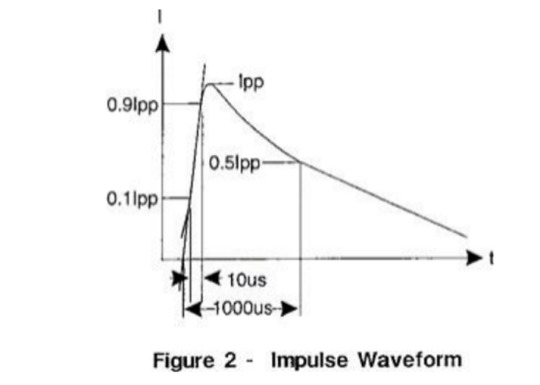
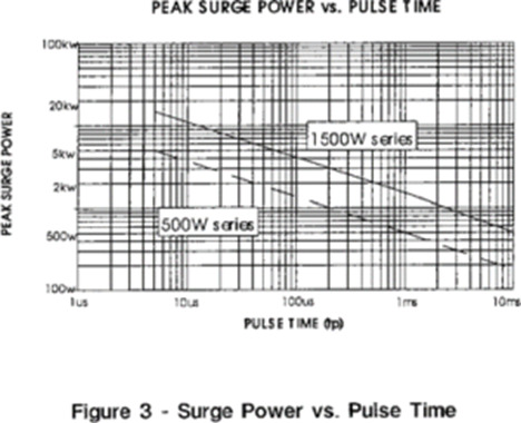
Rated Power and Surge Waveform
One of the most widely recognized surge wave forms is the double exponential pulse (Figure 2), defined by its rise time (tr) and duration (tp). The pulse duration (tp) is the time for the pulse current to decay to 50% of IPP. For example, a 10 × 1000 μs pulse has a 10 μs rise time and decays to 50% of its peak value within 1 ms.
The rated power of a suppressor is the product of VC and IPP:
Pp = VC × IPP
Guidelines for Choosing the Correct Transient Voltage Suppressor
Leiditech recommends the following steps to select devices for optimal transient suppression:
1. Determine the circuit’s maximum DC voltage or continuous operating voltage, considering nominal voltage and “high-side” conditions.
2. Select a TVS with a reverse isolation voltage (VRWM) equal to or greater than the circuit’s operating voltage.
3. Ensure the TVS draws negligible current under normal operation. A too-low working voltage may cause avalanche breakdown or excessive leakage current, affecting circuit performance.
4. Evaluate Peak Pulse Power (Pp): Characterize the circuit’s transient conditions (waveform, source, and pulse duration). Choose a TVS that can dissipate the expected peak pulse power.
5. Specify Maximum Clamping Voltage (VC): Select a TVS with a clamping voltage lower than the threshold that could damage the circuit.
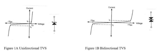
Unidirectional vs. Bidirectional TVS
A common misconception is that bidirectional TVS diodes are needed to suppress negative transient pulses. In reality, bidirectional TVS diodes are essential for:
l Communication applications or data lines with positive/negative signal oscillations.
l Applications requiring reduced capacitance.
For circuits with only positive signal levels, a unidirectional TVS is typically sufficient.
Operation principle:
l Under positive transients, the device avalanches and conducts in the reverse breakdown direction.
l Under negative surges, it conducts like a forward-biased diode, absorbing transient energy (except for low-capacitance devices, which must be bidirectionally connected to protect internal diodes from reverse surges).
Temperature Considerations
Transient voltage suppressors are designed for operation over a wide temperature range (typically -55°C to +155°C). For applications with specific temperature requirements, consider:
l Reverse Current (IR): Increases with temperature; refer to the datasheet for high-temperature leakage limits.
l Power Dissipation: Decreases as junction temperature rises. Peak power derates linearly from +25°C to the maximum rated temperature (Tmax); see the power derating curve for examples.
l Breakdown Voltage Temperature Coefficient (TCBV): Specified in the datasheet as the percentage change in VBR per degree Celsius.
If you’d like to learn more or have any questions, don’t hesitate to reach out:
Visit us at [en.leiditech.com]
#TVSDiodes #CircuitProtection #ESDProtection #SurgeProtection #Leiditech #ElectronicsDesign #PowerElectronics #TransientVoltage #TechTips #EngineeringSolutions #ElectronicComponents #DesignSmart #TVSGuide #EMCDesign
0 notes
Text
TI/VISHAY/SEMTECH ESD Models Replacement Guide by Leiditech
When international brand components face shortages or long lead times, Leiditech steps in!
As a leading brand in EMC solutions and component supply, Shanghai Leiditech offers a comprehensive alternative dictionary for international brands, including TI, NXP, SEMTECH, LITTELFUSE, ON-SEMI, PROTEK, VISHAY, DIODES, ST, ROHM, WE, Tyco, Wurth, AMAZING, and more. Below is our curated list of Leiditech ESD models substituting TI, VISHAY, and SEMTECH products, designed to serve customers efficiently.
TI ESD Models & Leiditech Alternatives
Leiditech ESDA05CP30 → TI TPD1E10B06DPYR
Leiditech USRV05–4 → TI TPD4E1U06DBVR
Leiditech USRV05–4 → TI TPD4S009DBVR
Leiditech USRV05–4 → TI TPD4S009DBVRG4
Leiditech USRV05–4 → TI TPD4E001DBVR
Leiditech LC0504F → TI TPD4E001DCKR
Leiditech LC0504F → TI TPD4E1U06DCKR
Leiditech LC0504F → TI TPD4S009DCKR
Leiditech LC0504F → TI TPD4S009DCKRG4
Leiditech ULC3311CDN → TI ESD351DPYR
Leiditech ULC3311CDN → TI TPD1E01B04DPYR
Leiditech ULC3311CDN → TI TPD1E01B04DPYT
Leiditech ULC3311CDN → TI TPD1E04U04DPYR
Leiditech ULC3311CDN → TI TPD1E04U04DPYT
Leiditech ULC3304P10 → TI ESD204DQAR
Leiditech ULC0524P → TI TPD4E05U06DQAR
Leiditech GBLC24C → TI ESD1LIN24DYFR
Leiditech GBLC24CQ → TI ESD1LIN24DYFRQ1
Leiditech SMC24–323Q → TI ESD2CAN24DCKRQ1
Leiditech SMC24LV → TI ESD752DBZR
Leiditech SMC24LVQ → TI ESD2CAN24DBZRQ1
Leiditech ESDA08CP → TI TPD1E10B09DPYR
Leiditech ESDA08CP → TI TPD1E10B09DPYT
Leiditech ULC0521CDN → TI ESD451DPLR
Leiditech ULC2411CDN → TI ESD761DPYR
Leiditech ESDA05CP30 → TI TPD1E10B06QDPYRQ1
Leiditech ULC0321C13 → TI TPD1E01B04DPLR
Leiditech ULC0321C13 → TI TPD1E01B04DPLT
Leiditech SR33–04AW → TI ESDS312DBVR
Leiditech SR33–04AW → TI ESDS314DBVR
VISHAY ESD Models & Leiditech Alternatives
Leiditech SD15C → VISHAY VLIN1616–02G
Leiditech SD15C → VISHAY VLIN1626–02G
Leiditech SD33CW → VISHAY VLIN3333–02G
Leiditech SD33CW → VISHAY VLIN3333–02G
Leiditech SDA05CW → VISHAY VESD05A5–06G
Leiditech SDA08T1 → VISHAY VESD08C1–02V
Leiditech SDA1511CDN → VISHAY VCUT0714BHD1
Leiditech SDA1511CDN → VISHAY VCUT0714A-HD1
Leiditech SDA15T1 → VISHAY VESD16C1–02V
Leiditech SDA24T1 → VISHAY VESD01C1–02V
Leiditech SDA3.3T1 → VISHAY VESD03C1–02V
Leiditech SDA36T1 → VISHAY VESD33C1–02V
Leiditech SM03 → VISHAY GSOT03C
Leiditech SM05 → VISHAY GSOT05C
Leiditech SM08 → VISHAY GSOT08C
Leiditech SM12 → VISHAY GSOT12C
Leiditech SM15 → VISHAY GSOT15C
Leiditech SM24 → VISHAY GSOT24C
Leiditech SM36 → VISHAY GSOT36C
Leiditech SMC05 → VISHAY GSOT05
Leiditech SMC08 → VISHAY GSOT08
Leiditech SMC12 → VISHAY GSOT12
Leiditech SMC15 → VISHAY GSOT15
Leiditech SMC24–323 → VISHAY VCAN26A2–03G
Leiditech SMC24–323 → VISHAY VCAN26B2–03G
Leiditech ULC0511CDN30 → VISHAY VBUS05L1-DD1
Leiditech SMC24–323 → VISHAY VCUT0505B-HD1
Leiditech ESDA05CP30 → VISHAY VESD05A1B-HD1
Leiditech ESDA05CP30 → VISHAY VCUT05B1-DD1
Leiditech ESDA33CP30 → VISHAY VESD03A1B-HD1
Leiditech ESDA33CP30 → VISHAY VCUT03B1-DD1
Leiditech ESD0521CH → VISHAY VCUT05E1-SD0
SEMTECH ESD Models & Leiditech Alternatives
Leiditech ESDA33CP30 → SEMTECH uClamp3301P
Leiditech LC03–3.3 → SEMTECH RClamp2502L
Leiditech LC0502N → SEMTECH RClamp0502N
Leiditech LC3304P8 → SEMTECH RClamp3304N
Leiditech SDA05W5 → SEMTECH RClamp0502A
Leiditech SDA1211CDN → SEMTECH uClamp1201P
Leiditech SDA1211CDN → SEMTECH uClamp1211P
Leiditech SDA2411CDN → SEMTECH uClamp2401P
Leiditech SDA3611CDN → SEMTECH uClamp3601P
Leiditech SRV05–4W → SEMTECH RClamp0554S
Leiditech ULC0502T3 → SEMTECH RClamp0502B
Leiditech ULC0504P → SEMTECH RClamp0504P
Leiditech ULC0504P → SEMTECH RClamp2504P
Leiditech ULC0504P → SEMTECH RClamp3304P
Leiditech ULC0511CDN30 → SEMTECH RCLAMP1521PQTCT
Leiditech ULC0511CDN30 → SEMTECH RCLAMP3331ZATFT
Leiditech ULC0511CDN30 → SEMTECH RCLAMP3521P.TNT
Leiditech ULC0511CDN30 → SEMTECH RClamp0521P
Leiditech ULC0511CDN30 → SEMTECH RClamp0521PA
Leiditech ULC0511CDN30 → SEMTECH RCLAMP0521PATCT
Leiditech ULC0511CDN30 → SEMTECH RClamp0521Z
Leiditech ULC0511CDN30 → SEMTECH RClamp0531T
Leiditech ULC0524P → SEMTECH RClamp0524P
Leiditech ULC0544M → SEMTECH RClamp0504M
Leiditech ULC3304P8 → SEMTECH TCLAMP3302N
Leiditech USRV05–4 → SEMTECH RClamp0504S
Leiditech ULC0321CDNH → SEMTECH UCLAMP3321ZAT
Leiditech ULC0521CH → SEMTECH RClamp4041ZA
Leiditech ULC0321CDNH → SEMTECH UCLAMP3321ZAT
Why Choose Leiditech?
With 16 years of brand operation, Leiditech products are widely used worldwide in diverse fields: automotive electronics, new energy, robotics, industrial automation, communications, mobile devices, smart homes, healthcare, security monitoring, instrumentation, intelligent lighting, and consumer electronics.
Our international brand alternative dictionary will be continuously updated. Stay tuned for more!
Visit us at [en.leiditech.com]
#ESDProtection #ComponentReplacement #TIAlternative #VISHAYSubstitute #SEMTECHReplacement #ElectronicsSolutions #LeadTimeSolution #Leiditech #ESDProtection #ComponentReplacement #TIAlternative #VISHAYSubstitute #SEMTECHReplacement #ElectronicsSolutions #LeadTimeSolution #SupplyChainSupport #EMC #ElectronicsManufacturing #SmartElectronics #IndustrialAutomation #AutomotiveElectronics
0 notes
Text
Vehicle Ethernet 100M/1000M ESD domestic device protection scheme
With the needs of digital electronic and autonomous driving systems in automobiles, the traditional CAN and LIN automotive communication protocols can no longer meet the signal transmission data needs of automobiles, and Ethernet is one of the more ideal improvement solutions; it can be applied to both Domain Control and Zonal Control )。
The advantage of Ethernet is that it can support different connection methods:
1. Directly connect the car’s central control computer, wireless network, ECU, sensor
2. Connect the car’s central control computer, wireless network, ECU and then connect the sensors with CAN/LIN
Leiditech electronics can replace PESD2ETH1GXT-Q, PESD1ETH1GLS-Q and PESD1ETH1GXLS-Q models
If you’d like to learn more or have any questions, don’t hesitate to reach out:
Visit us at [en.leiditech.com]
0 notes
Text
New ESD anti-static solution for NFC equipment interface
1、 What is an NFC device
NFC (Near-field communication) equipment is a wireless communication technology, which can realize short-range wireless communication and data exchange. It is based on Radio Frequency Identification (RFID) technology and Internet technology, using radio waves to transmit information between devices.
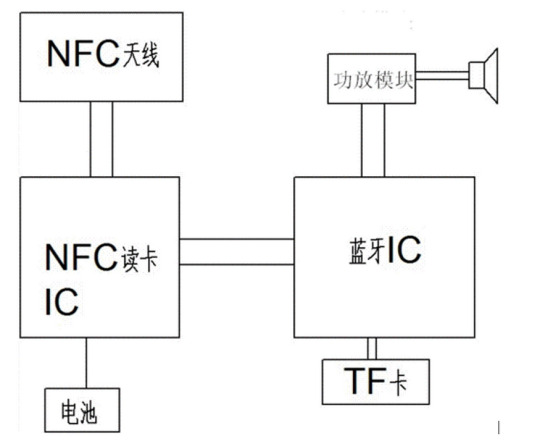
NFC devices usually consist of two parts: one is a reader/writer, used to read and write information on NFC tags or devices; The other is an NFC tag or device used to store and transmit information. For example, a mobile phone can serve as an NFC reader/writer, and an NFC label can be a regular piece of paper with information written on it, which can be read and written by the phone.
NFC technology has a wide range of applications in daily life, such as mobile payments, public transportation, smart homes, ticketing services, etc. Users can use NFC devices to pay for goods or services, enter public transportation or cultural venues, control household appliances, obtain ticketing information, and more. At the same time, NFC technology also provides more business opportunities for enterprises, such as promotional activities, providing customer service, and so on.
In short, NFC devices are a convenient and fast wireless communication technology that can provide users with a more convenient life experience and provide enterprises with more business opportunities.
2、 Necessity of NFC equipment anti-static
Anti static of Near-field communication equipment interface is very important, because static may have a negative impact on equipment performance, or even lead to equipment damage. In NFC device interfaces, charges may accumulate on the metal components of the device and generate an electric field around the interface. If static electricity is not properly handled, it may cause damage to the equipment.
3、 NFC equipment interface anti-static scheme
The following are some common methods to prevent static electricity from affecting NFC device interfaces:
Use metal shielding covers, use static eliminators, and use interface anti-static devices. At present, using anti-static devices ESD is the most effective and cost-effective solution. It is necessary to provide anti-static protection devices above 18V. Shanghai Leiditech has provided a board level design solution for the following series of devices.
NXPNTAG21 series
NXP MIFARE Classic Series
NXP MIFARE DESFire series
NXP MIFARE UItralight series
Sony FeliCa column
STMicroelectronics ST25 column
Infineon SLE column
Broadcom BCM2079x Series
Samsung TecTiles column
AMSAS395x series
If you’d like to learn more or have any questions, don’t hesitate to reach out: 📧 [[email protected]] 🌐 Visit us at [en.leiditech.com]
0 notes
Text
Face recognition access controller surge test and solution
Test product: face recognition access controller
Leiditech laboratory temperature and humidity: 26 degrees, 61%
Test standard: surge test, need to pass IEC61000–4–5
If you’d like to learn more or have any questions, don’t hesitate to reach out:
Visit us at [en.leiditech.com]
0 notes
Text
Introduction to 5V Ultra-Low Capacitance ESD Protection Diodes with Snapback in DFN1006 and DFN0603 Packages Shanghai Leiditech has launched two 5V
Shanghai Leiditech has launched two 5V ESD protection diodes with small packages (DFN1006 and DFN0603) and snapback characteristics, offering low clamping voltage (VCmax): ULC0521CLV and ULC0542CLV.
The following diagram illustrates the electrical parameters of standard ESD and snapback ESD diodes.
As we can see, for ordinary ESD (Electrostatic Discharge) protection devices, the clamping voltage (VC) gradually increases with the rise of peak pulse current (IPP). In contrast, snapback ESD devices exhibit a voltage reversal after breakdown: VC drops to a lower baseline first and then rises slowly. Therefore, the VC of snapback ESD diodes is significantly lower than that of ordinary ESD diodes. For specific parameter comparisons, please refer to the table below.
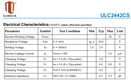
Parameter Definitions
VRWM : The maximum reverse voltage the TVS diode can withstand without conduction.
VBR: The voltage at which ESD protection activates, typically measured at 1 mA test current.
VC : The voltage clamped by the TVS diode during ESD events.
VCmax@A: Clamping voltage at peak pulse current (IPP) under 8/20μs waveform.
Cj : Parasitic capacitance in the TVS diode, affecting signal integrity.
For the two snapback models ULC0521CLV and ULC0542CLV in the upper rows of the table, the clamping voltage (VC) is 8V at an IPP of 6A.
For the two standard ESD diodes in the lower part, the clamping voltage (VC) is 25V at an IPP of 4A or 5A, which is much higher than that of the snapback types.
For the integrated circuits (ICs) to be protected, a lower clamping voltage of the ESD diode provides better protection for the IC and enhances its electrostatic resistance. Therefore, design engineers prefer to select snapback-type ESD diodes.
With ultra-low capacitance and low VC, ULC0521CLV and ULC0542CLV are ideal choices for ESD protection of high-speed signals, such as USB 3.0, RF signals, etc.
Leiditech Electronics is committed to becoming a leading brand in electromagnetic compatibility (EMC) solutions and component supply. We offer a wide range of products, including ESD, TVS, TSS, GDT, MOV, MOSFET, Zener diodes, and inductors. With an experienced R&D team, we provide personalized customization services to deliver the highest quality EMC solutions tailored to our customers' needs.
contact Doreen [email protected]
【Contact】 Doreen Xu
【Company】 Shanghai Leiditech Electronic Technology Co., Ltd.
【Sales Company】 HongKong Leiditech Technology Co., Ltd.
【Mobile Phone | Wechat】+86–18616228909
【Tel.】+86–21 50828806
【Email】[email protected]
【Web】en.leiditech.com
【Web search】leiditech
【Address】2nd Floor, Building A, №518 Kangshan Road,
Kangqiao Town, Pudong New District, Shanghai, China 201315
【Advantage】Our Products have been certified by Rohs,Reach, ISO9001
Products comply with IEC61000–4–2, ISO10605, 16949, ISO763–2, ISO17650–2, GB21437–2 standard.
Reliable quality, Reasonable price, Delivery fast.
【Supply】 ESD/TVS/GDT /TSS/SKY/MOS/DIODES/MOV
0 notes
Text
🌟Plastic Encapsulated Chip High-Traffic Varistor (MOV)🌟
In more and more DOB LED lamps, plastic encapsulated chip varistors (MOVs) have been widely used to replace plug-in and stacked chip varistors. Leiditech Electronics has achieved mass production, providing customers with replacements for 5D471K, 7D471K, and 10D471K models, featuring small packages and high current capacity. Here, we particularly recommend two high-traffic MOVs in 3225 (8x6x3.

and 4232 (10.4x8x4.1) packages.
1. Comparison Between 3225/4232 and Plug-In Types
The following lists common plug-in models (05D471K, 05D471KJ, 05D561K, 07D561KJ, 05D471K, 07D471KJ, 07D561K, 07D561KJ) and their voltage-equivalent 3225/4232 package models for comparison.
As shown in the comparison table above, even when compared with through-hole packages (05D and 07D), the 3225 and 4232 packages offer superior current capabilities, with the 4232 package even reaching 3.5KA. The table only shows partial voltage parameters.
2. Performance Advantages of Leiditech 3225 and 4232
Resistance to 300°C high temperature, avoiding virtual soldering.
Higher surge resistance, using nano-copper technology (refer to the parameter table above).
Good consistency.
3. Advantages of Surface Mount MOVs
Compact size: Meets the miniaturization and lightweight design requirements of modern electronic products.
Easy for automated production: Can be quickly and accurately installed via automated chip mounters, significantly improving production efficiency, reducing costs, and suitable for mass production.
Reliable performance: The surface mount package structure ensures a tighter contact with the circuit board, providing good electrical connection performance and ensuring stable and reliable signal transmission.
Good heat dissipation: The package structure of surface mount MOVs facilitates heat conduction and dissipation, quickly transferring the heat generated during resistor operation to the circuit board, which is then dissipated through the heat dissipation devices on the board.
Low parasitic inductance and fast response speed.
Diverse specifications: Available in various sizes and parameter specifications to meet the overvoltage protection needs of different electronic devices (examples listed above).
High surge current capability: Some surface mount MOVs have a high surge current tolerance, effectively absorbing instantaneous high-energy pulses such as those generated by lightning strikes and electrostatic discharge, providing reliable protection for electronic devices.
4. Application Fields
Surface mount MOVs are widely used in the following fields:
1) Consumer electronics: Mobile phones, laptops, tablets, digital cameras and camcorders, game consoles.
2) Home appliances: Batteries, air conditioners, washing machines, refrigerators.
3) Industrial field: Industrial automation equipment
Leiditech Electronics also provides surface mount varistors in other packages, including 0402, 0603, 0805, 0806, 1206, 1812, 2220, 3220, 4032, and 4635.
For specific parameters, please contact Leiditech's sales team or EMC specialists.
Leiditech Electronics is committed to becoming a leading brand in electromagnetic compatibility (EMC) solutions and component supply. We offer a wide range of products, including ESD, TVS, TSS, GDT, MOV, MOSFET, Zener diodes, and inductors. With an experienced R&D team, we provide personalized customization services to deliver the highest quality EMC solutions tailored to our customers' needs.
contact Doreen [email protected]
【Contact】 Doreen Xu
【Company】 Shanghai Leiditech Electronic Technology Co., Ltd.
【Sales Company】 HongKong Leiditech Technology Co., Ltd.
【Mobile Phone | Wechat】+86–18616228909
【Tel.】+86–21 50828806
【Email】[email protected]
【Web】en.leiditech.com
【Web search】leiditech
【Address】2nd Floor, Building A, №518 Kangshan Road,
Kangqiao Town, Pudong New District, Shanghai, China 201315
【Advantage】Our Products have been certified by Rohs,Reach, ISO9001
Products comply with IEC61000–4–2, ISO10605, 16949, ISO763–2, ISO17650–2, GB21437–2 standard.
Reliable quality, Reasonable price, Delivery fast.
【Supply】 ESD/TVS/GDT /TSS/SKY/MOS/DIODES/MOV
#EMCsolutions#TVSProtection#InnovationInElectronics#Leiditech#TechThatProtects
0 notes
Text
ED Light Fails? This “Invisible Self-Healing” Solution is Trusted by 90% of Engineers!
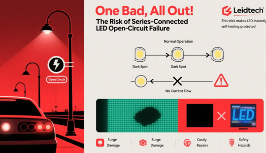
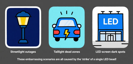
How Deadly is LED Open-Circuit Failure?
Imagine: Outdoor streetlights suddenly go dark in segments, car taillights lose a bead, or mall LED screens develop dark spots — all often caused by a single open-circuited LED bead.
Series-connected LEDs fear “one fails, all fail!” Thermal shock, ESD, or lightning strikes can blackout entire lighting systems, causing costly repairs.
Leiditech LED Shunt Solution: Invisible Self-Healing for LED Failures
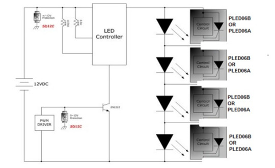
(Diagram: PLED06B control circuit with bypass logic for open-circuit LEDs)
As an EMC innovation leader, Leiditech’s LED Shunt open-circuit protection device revolutionizes traditional protection. Take the flagship PLED06CB as an example:
✅ Dual Protection Mechanism
▶ Anti-blackout: Bypasses each failed bead in series-connected LED strings, keeps the rest lit
▶ Lightning and Surge Resistance: Easily withstands 24A surges, ensuring LED beads are not instantly “blown up” by high voltage.
✅ Intelligent Response & Auto-Reset
▶ Normal State: High impedance (leakage <10μA), zero impact on brightness
▶ Fault State: <1ns ultra-fast conduction when voltage hits breakdown threshold (e.g., 6V), bypassing faulty beads
▶ Auto-Recovery: Automatically resets to high impedance after the fault is cleared (e.g., bead replacement or system reboot)
Full-Scenario Applications
1. Outdoor & Industrial Lighting (Streetlights, tunnels, billboards):
- Meets CQC3158–2024 (China energy efficiency standard) energy efficiency, survives lightning surges, ensures single-fault resilience
2. Automotive Electronics (Headlights, taillights, turn signals):
- Complies with ISO 16750–3 vibration/thermal standards
- Combined with automotive TVS (SM8S33CA) and ESD (SMC24) for full-power protection
3. Smart Home & Commercial Lighting (LED strips, panel lights):
- Eliminates dark spots from single-bead failure
- PWM (Pulse Width Modulation) dimming compatible — protection remains active during dimming
Leiditech’s PLED Series LED shunts can perfectly replace those of other brands.
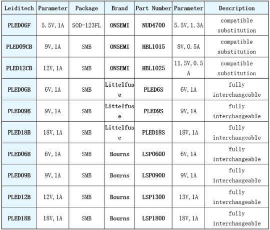
3-Step Selection Guide
Core Parameter Matching
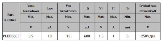
- Breakdown Voltage (VBR): ≥1.5x LED operating voltage (e.g., 5.5V VBR for 3.3V LEDs)
- Holding Current (IH): ≥5mA (ensures sustained conduction)
- On-State Current (IT): 1A max (high-power tolerance)
- Package: SOD-123FL (compact) / SMB (high-power)
2. Design Tips
- Layout: Place LED Shunt close to LED terminals to minimize parasitic inductance
- Thermal Management: Calculate conduction power (P=Vf×I), ensure adequate heat dissipation
3. Certifications
- UL, VDE, IEC 62031 compliant
- Accelerates CQC3158–2024 energy efficiency compliance
Leiditech: Beyond Components — Total Technical Support
From “single-fault blackout” to “invisible bypass,” LED Shunt ensures:
- Outdoor Lighting: 10+ year lifespan via surge protection
- Automotive: Zero-fault safety compliance
- Smart Home: Seamless user experience
Unique Services:
- Free EMC lab testing (ESD, surge, EFT)
- Customizable parameters for high-voltage/high-frequency scenarios
- “Zero-fault” combo solutions (PTC+TVS+ESD) for multi-risk protection
Leiditech — Leading EMC Solutions Provider
- Specializing in ESD, TVS, TSS, GDT, MOV, MOSFET, inductors.
- Custom R&D team ensures tailored protection for your application.
If you’d like to learn more or have any questions, don’t hesitate to reach out:
Visit us at [en.leiditech.com] #LEDProtection #SelfHealingTech #Leiditech #NoMoreBlackouts #SmartLighting #AutoLighting #IndustrialLED #InvisibleFix #ZeroDowntime #PLEDSeries #SurgeProtection #ESDShield #NextGenLighting #EngineerTrusted #TechWithoutFailure
0 notes
Text
Introduction to Lin Bus and Special Devices for Electrostatic Surge Protection
1、 Introduction to Lin Bus
A. Definition of Lin Bus
Lin bus is a serial communication bus suitable for communication between automotive electronic control units (ECUs).
B. Characteristics of Lin Bus
The Lin bus adopts a single end drive and differential transmission method, which has the characteristics of high-speed transmission and strong anti-interference performance.
C. Application scope of Lin bus
The Lin bus is mainly used for communication between electronic control units (ECUs) in automobiles, such as engine control units, transmission system control units, body control units, and so on. The emergence of the Lin bus enables data exchange and communication between ECUs of different brands, systems, and functions, thereby improving the overall performance and safety of automobiles.
2、 Problems with Lin Bus
A. Hazards of static surges
Static surges and other factors can damage the performance and stability of the Lin bus.
B. Stability and reliability issues of Lin bus
There are also some problems with the Lin bus in practical applications.
3、 Design of electrostatic surge protection
A. Hardware protection measures
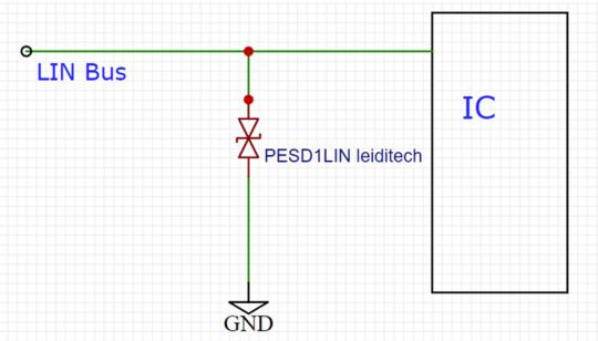
The design of electrostatic surge protection needs to start from both hardware and software aspects. In terms of hardware, measures such as protective circuits can be taken to limit electrostatic surge voltage, such as using protective circuits composed of TVS diodes, inductors, capacitors, etc.
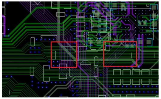
Suggestions for the layout of ESD devices
a) Place the device as close as possible to the input or connector.
b) Minimize the path length between the device and the protected line.
c) Keep parallel signal paths to a minimum.
d) Avoid running protected conductors in parallel with unprotected conductors.
e) Minimize the conductive circuits of all printed circuit boards (PCBs), including power and ground circuits.
f) Minimize the transient return path length to ground.
g) Avoid using shared transient return paths to common ground points.
h) Try to use ground planes, multi-layer printed circuit boards, and ground through holes as much as possible.
B. Software protection measures
In terms of software, error Check digit (CRC) and other technologies can be used to detect errors in data transmission, so as to ensure the reliability of data.
4、 The Importance of Lin Bus in the Field of Automotive Electronics
A. Advantages of Lin Bus
The Lin bus has the characteristics of high-speed transmission and strong anti-interference performance.
B. The Application Prospects of Lin Bus
In the future field of automotive electronics, the Lin bus will still play an important role and play an important role.
Summary
The interface protection of electronic products requires the use of overvoltage protection devices. Many engineers are aware of the need to use protection devices, but due to improper selection or failure to follow the design principles of ESD circuit PCB, the product fails static or EMC testing, wastes manpower and financial resources, and causes product delays or over design, resulting in cost pressure. Leiditech Electronics provides customers with electromagnetic compatibility EMC design services, providing laboratory testing for free. We aim to efficiently and conveniently complete the design for our customers. We hope that more customers can quickly pass EMC’s projects and improve product reliability as much as possible.
Shanghai Leiditech Electronic Electromagnetic Compatibility Laboratory provides free testing and peripheral electrostatic protection reference circuits.
If you’d like to learn more or have any questions, don’t hesitate to reach out:
Visit us at [en.leiditech.com] #LinBus#AutomotiveElectronics #SurgeProtection #EMC #ElectromagneticCompatibility #ESD #TechDesign #AutomotiveTech #VehicleInnovation #CircuitProtection #ElectronicsEngineering #CarSafety #Leiditech
0 notes
Text
EMC Design Pit Avoidance Guide:
Four no mnemonics
Why does your well-designed product fail EMC testing? The EMC team at Leiditech shares 4 practical EMC design techniques summarized in the “Four No” principles to help you avoid common pitfalls!
Principle 1: Make Current Take the Shortest Path, Not a Detour
Core Logic: High-frequency currents follow the “path of minimum inductance”. Larger loops → stronger radiation!
Key Insights from Leiditech Lab:
l Signal currents must form closed loops, with return paths closely following the outgoing paths.
l Low-frequency (kHz-level) currents follow the “path of minimum resistance”, with possibly dispersed return paths; high-frequency (MHz-level) currents follow the “path of minimum inductance”, with return paths closely adhering to the main trace.
l Design Tip: Place high-speed signals adjacent to their return planes and reduce the spacing between the signal layer and the ground plane.
Principle 2: Do Not Split the Signal Return Plane
Leiditech EMC engineers’ golden rule: Provide a complete return plane for all signal currents. For low-frequency signals prone to interference or likely to cause board-level interference, use dedicated trace layers to route return currents back to the source rather than splitting the plane. Arbitrary slotting/dividing the ground plane can cause abrupt changes in return paths → surging EMI!
Exceptions:
Independent return traces may be used only for isolating low-frequency sensitive signals (e.g., audio power supplies), provided:
l The independent layer has a separate return path and does not cross high-frequency planes.
l Consult Leiditech EMC experts to avoid case-by-case misapplication.
Warning: A complete plane is the optimal solution in 99% of scenarios!
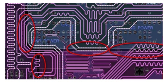
Principle 3: Do Not Route High-Speed Circuits Between Connectors
This is one of the most common issues in PCB designs evaluated by Leiditech Lab. Many simple designs that could easily meet EMC requirements (with no extra cost or effort) end up requiring extensive shielding and filtering due to violating this rule.
Why connector placement matters: At frequencies below several hundred MHz, wavelengths can be meter-scale or longer. While the PCB itself acts as a low-efficiency “antenna” due to its small electrical size, cables or external devices connected to the PCB can become efficient radiators.
When signal currents flow on traces and return through a complete plane, the voltage difference between any two points on the plane is typically proportional to the in-plane current. When all connectors are aligned along one side of the PCB, voltage differences between them are negligible. However, if high-speed circuits are routed between connectors, potential differences of several millivolts or more may arise, driving currents into connected cables and causing excessive radiation emissions.
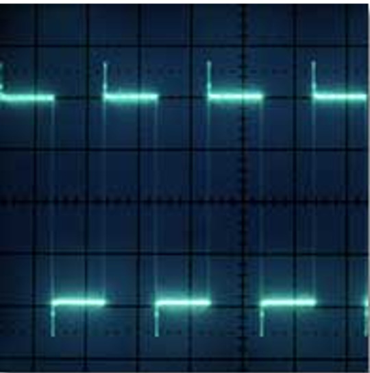
Principle 4: Do Not Blindly Pursue the Fastest Edge; Control Signal Transition Time
Fast edges (1ns) → harmonics up to 2GHz; slow edges (5ns) → harmonics <500MHz.
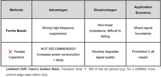
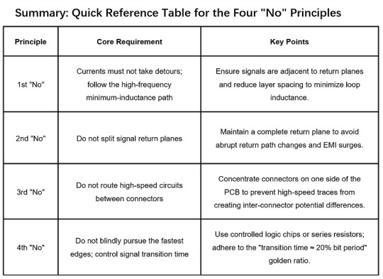
Leiditech EMC Team’s Golden Ratio: Transition time ≈ 20% of the bit period (e.g., for a 100MHz clock, control edge rates within 2ns).
Leiditech Electronics is committed to becoming a leading brand in electromagnetic compatibility (EMC) solutions and component supply. We offer a wide range of products, including ESD, TVS, TSS, GDT, MOV, MOSFET, Zener diodes, and inductors. With an experienced R&D team, we provide personalized customization services to deliver the highest quality EMC solutions tailored to our customers’ needs.
If you’d like to learn more or have any questions, don’t hesitate to reach out: 📧 [[email protected]] 🌐 Visit us at [en.leiditech.com] #NoMoreBuzzing #DriveInPeace #SmartCarTech #ElectromagneticShield #AutoInnovation #CarSafetyFirst #ShanghaiLeditech #NextGenDriving #HornHarmony #AutoElectronics #EMCProtection #StaticNoMore #SmartDriveSolutions
0 notes
Text
Automotive Electronic Horn and Electromagnetic Compatibility
Hey hey, hello everyone, today I want to talk to you about a super interesting topic — electromagnetic compatibility of car electronic horns! Yes, that’s right. What we’re talking about is the horn that makes you hear various beeps and alarm sounds on the road!
Sounds boring? Don’t worry, I promise this topic will make you laugh heartily! Alright, let’s get started!
Firstly, let’s explain what electromagnetic compatibility is. Simply put, it refers to the peaceful coexistence of various electronic devices without mutual interference. You heard me right, it’s just so magical! When various electronic devices are installed in our cars, conflicts may arise between them. It’s like a family argument, where electronic devices argue with each other and create a bunch of messy problems. This is not for fun!
So what should we do? It’s okay, Shanghai leditech Electronics is coming to save the world! They provide a complete set of electromagnetic compatibility and electrostatic surge protection solutions to keep your car quiet and balanced during electronic device disputes. This is like installing a pair of earplugs on your car to protect it from the noise and interference of electronic devices, no longer being affected by chaos. That’s really great!
The protection plan of Shanghai leditech Electronics is not only about the horn, but also helps your vehicle resist the attack of static surges. Do you know that electrostatic surges are like a sudden attack from an uninvited guest, which may surprise your car’s electronic devices. Shanghai leditech Electronics is like putting an anti-static jacket on your car, allowing them to weather this sudden electrostatic attack with peace of mind.
So, whether you’re racing on the highway or shuttling through the city, Shanghai leditech Electronics’ electromagnetic compatibility solution can provide you with protection. It’s like installing a superhero Talisman on your car to ensure that it is safe in the dispute over electronic devices. He’s just a savior!
So, dear friends, remember to consider electromagnetic compatibility when choosing automotive electronic devices. Oh my god, do you want me to write longer? Are you sure? Okay, I will do my best to meet your requirements, even though it may make me a bit out of breath!
We just mentioned the electromagnetic compatibility issue of car electronic horns, now let’s delve deeper into it. You may be curious why electronic devices in cars argue with each other? Actually, this is not surprising. Imagine listening to music in the car and suddenly the horn emits a piercing beep, which startles you. Or perhaps you are enjoying a comfortable driving experience when suddenly the central control system crashes, leaving you confused. These are all consequences of electromagnetic compatibility issues.
There are more and more electronic devices in Hyundai Motor Company. From speakers to navigation systems, from Parking sensor to wireless chargers, each device sends electromagnetic signals. It’s like a group of noisy children shouting at each other, creating a scene of noisy chaos. As a result, they may interfere with each other’s normal work, leading to various problems.
So, how does Shanghai leditech Electronics provide a complete set of electromagnetic compatibility and electrostatic surge protection solutions? Let me uncover the mystery for you! They use advanced technology and professional knowledge to design a series of solutions to ensure harmonious coexistence of your automotive electronic devices.
Firstly, they ensure that each device can operate stably in an electromagnetic environment through precise electromagnetic compatibility testing. This is like holding a dedicated peace conference for electronic devices, allowing them to communicate with each other in a harmonious atmosphere, rather than arguing loudly.
Secondly, Shanghai leditech Electronics also provides electrostatic surge protection solutions to prevent electrostatic attacks from uninvited guests. They will equip your car with professional Antistatic device, just like putting on a lovely anti-static clothing for your car. In this way, even if static electricity suddenly strikes, your electronic devices can still be unscathed, just like in an invincible defense feast.
Overall, the electromagnetic compatibility and electrostatic surge protection solutions provided by Shanghai leditech Electronics are like adding a magical layer of protective armor to your car. They ensure that your electronic devices coexist harmoniously in the electromagnetic environment of the vehicle, avoiding unnecessary arguments and conflicts. Moreover, they can also protect your equipment from static electricity and maintain a safe and stable environment inside your car
Imagine galloping happily on the highway, enjoying the beauty of music without being startled by the sudden piercing sound of the horn. You can focus on driving without getting distracted by the sudden collapse of the central control system. The protection plan of Shanghai leditech Electronics is like adding a safe and reassuring guarantee to your car.
So, dear friends, when designing automotive electronic devices, please remember the importance of electromagnetic compatibility. Don’t let your car get caught up in device disputes and chaos. Choose Shanghai leditech Electronics’ complete set of electromagnetic compatibility and electrostatic surge protection solutions to make your driving experience more reassuring and enjoyable.
Lei Mao provides the following standard design and rectification plan:
FCC Part 15
ISO 7637–1
ISO 11452–4
SAE J1772
GB/T 18387: 2017
ISO 7637–2
ISO 11452–8
SAE/USCAR-28
ICNIRP 2010
ISO 7637–3
ISO 11452–9
UN/ECE Regulation 10
IEC CISPR 16–1–1
ISO 10605
ISO 11452–11
IEC CISPR 16–1–4
ISO 11452–1
ISO 16750–2
IEC CISPR 25
ISO 11452–2
ISO 17025
GMW3059
GMW3091
GMW3172
GMW14241
If you’d like to learn more or have any questions, don’t hesitate to reach out: 📧 [[email protected]] 🌐 Visit us at [en.leiditech.com]
#NoMoreBuzzing#DriveInPeace#SmartCarTech#ElectromagneticShield#AutoInnovation#CarSafetyFirst#ShanghaiLeditech#NextGenDriving#HornHarmony#AutoElectronics#EMCProtection#StaticNoMore#SmartDriveSolutions
0 notes
Text
New ESD anti-static solution for NFC equipment interface

1、 What is an NFC device
NFC (Near-field communication) equipment is a wireless communication technology, which can realize short-range wireless communication and data exchange. It is based on Radio Frequency Identification (RFID) technology and Internet technology, using radio waves to transmit information between devices.
NFC devices usually consist of two parts: one is a reader/writer, used to read and write information on NFC tags or devices; The other is an NFC tag or device used to store and transmit information. For example, a mobile phone can serve as an NFC reader/writer, and an NFC label can be a regular piece of paper with information written on it, which can be read and written by the phone.
NFC technology has a wide range of applications in daily life, such as mobile payments, public transportation, smart homes, ticketing services, etc. Users can use NFC devices to pay for goods or services, enter public transportation or cultural venues, control household appliances, obtain ticketing information, and more. At the same time, NFC technology also provides more business opportunities for enterprises, such as promotional activities, providing customer service, and so on.
In short, NFC devices are a convenient and fast wireless communication technology that can provide users with a more convenient life experience and provide enterprises with more business opportunities.
2、 Necessity of NFC equipment anti-static
Anti static of Near-field communication equipment interface is very important, because static may have a negative impact on equipment performance, or even lead to equipment damage. In NFC device interfaces, charges may accumulate on the metal components of the device and generate an electric field around the interface. If static electricity is not properly handled, it may cause damage to the equipment.
3、 NFC equipment interface anti-static scheme
The following are some common methods to prevent static electricity from affecting NFC device interfaces:
Use metal shielding covers, use static eliminators, and use interface anti-static devices. At present, using anti-static devices ESD is the most effective and cost-effective solution. It is necessary to provide anti-static protection devices above 18V. Shanghai Leiditech has provided a board level design solution for the following series of devices.
NXPNTAG21 series
NXP MIFARE Classic Series
NXP MIFARE DESFire series
NXP MIFARE UItralight series
Sony FeliCa column
STMicroelectronics ST25 column
Infineon SLE column
Broadcom BCM2079x Series
Samsung TecTiles column
AMSAS395x series
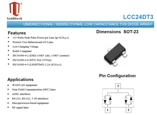
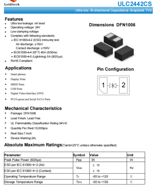
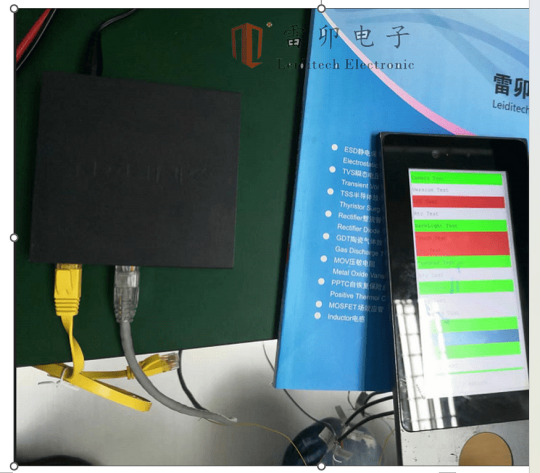
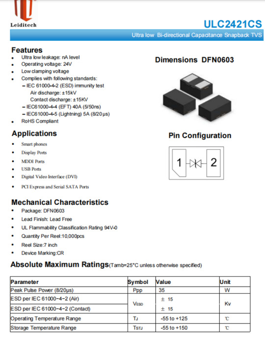
This article discusses the use of Shanghai Leiditech’s large scan ESD devices ULC2421CS and ULC2442CS to protect these chips on small devices such as smartphones, watches, and bracelets.

If you’d like to learn more or have any questions, don’t hesitate to reach out: 📧 [[email protected]] 🌐 Visit us at [en.leiditech.com]
#StaticShield #NFCProtection #SmartTechDefense #ESDGuardians #SnapBackTech #ShanghaiLeiditech #WearableTechSafety #IoTSecurity #ElectrostaticArmor #EMCDesign #FutureProofTech #TechThatProtects #ESDsolution #TechReliability
0 notes
Text
Shanghai Leiditech TVS transient voltage suppression tube — SMA/SMB/SMC packaging can achieve multiple powers

1. What is TVS
TVS is the abbreviation for Transient Voltage Suppressor. TVS diode is a protective component used to protect electronic components from voltage fluctuations. The working principle of a TVS diode is to have the properties of a regular diode within its forward operating range. When the reverse voltage exceeds its rated reverse voltage, the voltage will rapidly increase, changing the high impedance between its two poles into low impedance at a speed of 10 to the negative 12th power second. It absorbs surge power of up to several kilowatts, placing the voltage box between the two poles at a predetermined value, effectively protecting precision components in electronic circuits, Protects against damage from various surge pulses. When the overvoltage disappears, the TVS diode will automatically reset.
2. Characteristics of TVS
1) Fast response speed: The transient suppression diode has a very fast response speed and can respond to voltage changes within a ns level time, thereby protecting the circuit from damage caused by transient voltage, electromagnetic interference, and other factors.
2) High reverse voltage: Usually able to withstand a voltage of several hundred volts, which can protect the circuit from damage caused by high voltage.
3) Effective suppression of transient voltage: Transient suppression diodes can effectively suppress transient voltage and prevent it from entering the protected circuit.
4) Small size and high power density: Transient suppression diodes are usually smaller in size and higher in power density than other protection components, providing effective protection in small devices
5) Long life: Transient suppression diodes have a long service life and can withstand multiple high-power transient voltage surges without affecting their performance.
6) Environmental protection: Compared with other protective components, transient suppression diodes have better environmental performance due to the absence of combustibles and the release of toxic gases.
7) In addition, it has the characteristics of high transient power, low leakage current, small breakdown voltage deviation, and easy control of clamping voltage. In summary, TVS diodes have the advantages of fast response speed, small size, good protection effect, and high reliability, making them one of the ideal components for protecting electronic components.
3. TVS application field
1)TVS transient suppression diodes can be widely used in the protection of various electronic devices. The following are some common application areas: 1) Electronic device protection: TVS transient suppression diodes can be used to protect various electronic devices, such as televisions, computers, mobile phones, audio systems, etc. from damage caused by transient voltage fluctuations.
2) Power line protection: TVS transient suppression diodes can be used to protect power lines from transient voltage, lightning, and other factors.
3) Communication network protection: TVS transient suppression diodes can be used to protect communication equipment, such as switches, routers, etc. from electromagnetic interference and lightning and other factors.
4) Automotive electronic protection: TVS transient suppression diodes can be used to protect automotive electronic devices, such as engine controllers, in car audio systems, from voltage surges, electromagnetic interference, and other factors.
5) Aerospace field: TVS transient suppression diodes can be used to protect aerospace electronic equipment from electromagnetic interference damage.
In summary, TVS transient suppression diodes can be widely applied in the protection field of various electronic devices, and their main function is to protect electronic devices from factors such as voltage surges, transient voltage, electromagnetic interference, etc.
4. Shanghai Leiditech Electronics SMA/SMB/SMC Packaging TVS Power
The Shanghai Leiditech Electronic SMA, SMB, and SMC packaged TVS series can achieve various power and voltage ranges for selection as shown in the table below:
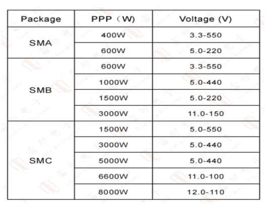
5. How to choose packaging for TVS with the same power
When selecting the packaging size of TVS transient suppression diodes with the same power, the following factors should be considered:
1) Maximum pulse current: When selecting the packaging size, it is necessary to consider the maximum pulse current that the TVS transient suppression diode can withstand, and to choose a suitable size to ensure that it can withstand the required current.
2) Voltage level: The packaging size needs to be selected based on the reverse voltage that the TVS transient suppression diode needs to withstand.
3) Heat dissipation capability: When selecting packaging, it is also necessary to consider the issue of TVS transient suppression diode heat dissipation. If the ambient temperature is high or the required power is high, it is necessary to choose a package with good heat dissipation performance to ensure the stable operation of the TVS transient suppression diode. 4) Design space: Different packaging sizes correspond to different circuit board space requirements, which need to be selected based on actual situations.
4) In summary, when selecting the packaging size of TVS transient suppression diodes with the same power, it is necessary to comprehensively consider factors such as maximum pulse current, voltage level, heat dissipation capacity, and circuit board design space.
The following are representative models of Leiditech for reference:
SMA packing:
SMAJ3.3CALIR,SMAJ24CA,SMAJ36CA,SMAJ550CA,6AJ5.0CA,6AJ24CA,6AJ36CA,6AJ220CA,
SMB packing:SMBJ3.3CA,SMBJ24CA,SMBJ36CA,SMBJ550CA,10BJ5.0CA,10BJ24CA,10BJ36CA,10BJ440CA,SMB15J5.0CA,SMB15J24CA,SMB15J36CA,SMB15J220CA,SMB30J11CA,SMB30J24CA,SMB30J36CA,SMB30J150CA,
SMC packing:SMCJ5.0CA,SMCJ24CA,SMCJ36CA,SMCJ550CA,SMDJ5.0CA,SMDJ24CA,SMDJ36CA,SMDJ440CA,5.0SMDJ5.0CA,5.0SMDJ24CA,5.0SMDJ36CA,5.0SMDJ440CA,6.6SMDJ11CA,6.6SMDJ24CA,6.6SMDJ36CA,6.6SMDJ100CA,8.0SMDJ12CA,8.0SMDJ24CA,8.0SMDJ36CA,8.0SMDJ110CA
Leiditech can provide various interface electrostatic lightning protection solutions to solve electromagnetic compatibility problems for customers, and provide more protection solutions,Please search for the mini program “EMC Electromagnetic Compatibility Community” on WeChat. Welcome to contact Hu Gong 18016225001.
If you’d like to learn more or have any questions, don’t hesitate to reach out: 📧 [[email protected]] 🌐 Visit us at [en.leiditech.com]
#TVSDiode #CircuitProtection #SurgeProtection #ElectronicsDesign #EMC #ESDProtection #Leiditech #ElectronicsEngineering #PowerElectronics #VoltageSpike #TechTips #ComponentSelection #SmartDesign #WeChatMiniProgram #SMA #SMB #SMC #ShanghaiTech #ElectronicComponents
0 notes
Text
Leiditech LCD screen ESD Protection solutions
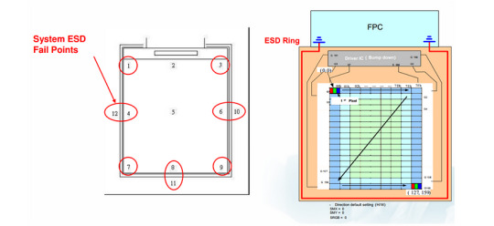
Recently Leiditech ElectronicsEMCEngineers have received many inquiries from classmates about LCD screensESDInvalid rectification cases,Actually, it is highly recommended that electronic engineers consider it during designesdprotect,Here is a science popularization。 1、The generation of static electricity Static electricity is an objective natural phenomenon,There are various ways to generate it,If in contact with、friction、Induction between electrical appliances, etc。The characteristic of static electricity is long-term accumulation、high voltage、Low battery、The characteristics of low current and short action time。Human body movements or contact with other objects,separate,Factors such as friction or induction,It can generate static electricity of thousands or even tens of thousands of volts。 2、Industry troubles ESD(electrostatic discharge )There are two types of damage and damage to electronic products: sudden damage and potential damage。The so-called sudden injury,Refers to severe damage to the device,Loss of function。This type of damage can usually be detected during quality inspection during the production process,Therefore, the main impact on the factory is reworkserviceCost of。And potential damage refers to partial damage to the device,The function has not been lost yet,And it cannot be detected during the inspection of the production process,But during use, it can make the product unstable,Sometimes good and sometimes bad,Therefore, it poses a greater threat to product quality。 For touch products,If the display screen resistsESDWeak ability,In daily use,There is a possibility of beingESDCausing abnormal product operation,Crash,Even damaging and causing other safety issues,So currently, all types of LCD touch products must undergoESDAnd other surge current tests。 3、LCD screenESDtest failThe main phenomenon of 3.1、No display(Black or white screen) →systemfailorLCM fail(Backlight/LCD) 3.2、Display broken lines。 3.3、Display flower screen →The system can be restored to normal after restarting。 3.4、The display will flash once and it will be normal。 4、ESD Fail Type of: 4.1、IC Register value error; 4.2、MIPI Vedio Data error; 5、ESD Protection Hardware protection: 5.1、increase ESD Ring; It is strongly recommended to increase the number of static electricity contactsTVS ESDdevice,Utilize its anti-static characteristics,Forming an electrostatic discharge circuit,Enhanced protection。

The interface protection of electronic products requires overvoltage protection devices,Many engineers realize the need to use protective devices,But due to improper selection or failure to follow ESD circuit PCB Design principles,Causing productElectrostatic testingor EMC Test failed,Multiple product validation tests,Waste of manpower and financial resources,Things that cause product delays always happen,Or over designed,Causing cost pressure。
Leiditech Electronics provides customers with electromagnetic compatibility EMC Design Services for,Provide a laboratory for thorough testing,Efficient from customers, Easy to control and complete the design,Hope to provide more customers with quick access EMC Project for,Make every effort to improve product reliability。Leiditech Electronic Electromagnetic Compatibility Laboratory,Provide reference circuit for peripheral electrostatic surge protection。
Here’s a polished and professional English version of your content for use on your website, technical blog, or marketing materials:
Leiditech LCD Screen ESD Protection Solutions
Recently, EMC engineers at Leiditech Electronics have received numerous inquiries from clients regarding ESD failures in LCD screens. In fact, it is highly recommended that electronic engineers consider ESD protection during the design phase. Here is a brief technical overview to help raise awareness and offer solutions.
1. Understanding Static Electricity
Static electricity is a naturally occurring phenomenon that can be generated in many ways — such as contact, friction, or induction between electronic devices. Its characteristics include:
Long accumulation time
High voltage
Low charge
Low current
Extremely short action duration
When the human body comes into contact with, separates from, or rubs against other materials, static voltages of several thousand to tens of thousands of volts can be generated.
2. Industry Challenges
Electrostatic Discharge (ESD) can cause two main types of damage to electronic products:
Catastrophic (Sudden) Damage: Immediate and visible failure of components, often caught during production quality checks. This results in rework and increased service costs.
Latent (Potential) Damage: Partial damage that does not immediately affect function and often goes undetected during production. However, it can cause product instability during use — creating unpredictable failures, crashes, or even safety risks.
For touch-enabled products, if the LCD display lacks proper ESD protection, there is a risk of:
System crashes
Abnormal behavior
Permanent damage during daily use
This is why ESD and surge protection testing is mandatory for all modern LCD touch products.
3. Common Symptoms of LCD ESD Failure
No display (black or white screen) — Often indicates system failure or LCM (LCD Module) failure
Broken lines on display
“Flower screen” or distorted display — Sometimes restored after a reboot
Display flickers once, then returns to normal
4. Typical Causes of ESD Failure
IC register value errors
MIPI video data errors
5. Hardware-Based ESD Protection Recommendations
5.1 Add ESD Protection Devices (TVS Rings)
It’s strongly advised to add TVS (Transient Voltage Suppression) diodes to contact points to form an electrostatic discharge path and enhance protection.
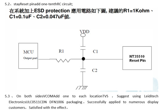
5.2 Add an RC Circuit to the Reset Pin
This helps stabilize the reset signal during unexpected electrostatic events.
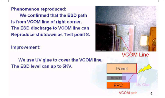
5.3 Add TVS Diodes on VCOM Pins
Place one TVS diode on each side of the VCOM line. Recommended model: Leiditech ULC0511CDN (DFN1006 package) This has been successfully implemented in various customer displays with excellent results.
5.4 Insulate Exposed Traces on the Panel
Use insulation adhesive or protective tape to cover exposed panel wiring to prevent static discharge.
6. Design Matters: Avoiding Common ESD Pitfalls
While many engineers recognize the need for ESD protection, failures still occur due to:
Improper device selection
Ignoring PCB layout principles for ESD circuits
This results in failed electrostatic or EMC testing, repeated verification cycles, wasted time and resources, and ultimately delays in product release. Overdesign can also increase production costs.
Leiditech: Your EMC & ESD Design Partner
Leiditech Electronics provides:
Professional EMC design services
A dedicated electromagnetic compatibility (EMC) lab
Reference circuits for electrostatic and surge protection
We help customers design more reliable products and pass EMC certifications efficiently. Leiditech is committed to improving product robustness and helping customers meet compliance faster.
If you need tailored protection solutions for your display or interface circuits, don’t hesitate to contact Leiditech Electronics.
Let me know if you want this formatted into a downloadable PDF, presentation deck, or social media post!
Visit us at [en.leiditech.com] #ESDProtection #LCDDesign #HardwareDesign #TechTips #ElectronicsEngineering #EMCDesign #Leiditech #ProductReliability #StaticElectricity #TVSdiodes #PCBDesign #TechBlog #ElectronicsTips #ElectrostaticDischarge #ManufacturingQuality #EngineeringSolutions #DisplayTechnology #DesignMatters
0 notes
Text
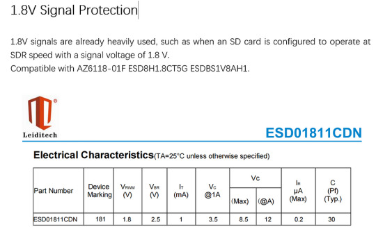
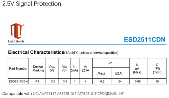
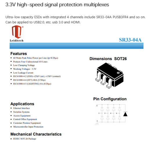
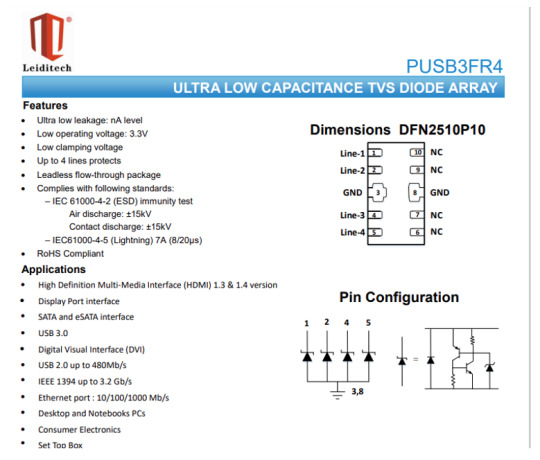
1. 8V 2. 5V 3. 3V signal is popular, how to design and select ESD, see this article is enough
At present, the main chips of electronic devices involved in fields such as autonomous driving, telemedicine, smart cities (such as DSPs, CUP, MCUs, ARM, DDR, etc.). There will be multiple low voltage supply channels such as 1.8V, 1.5V, 1.15V, 1.05V, etc., but in ESD Electrostatic discharge and transient voltage suppression products on the industry’s mainstream low voltage only to 3.3V, if the use of higher breakdown and clamp voltage devices can not be a good appeal of the main chip to provide favorable protection; the national high-tech enterprise Leiditech Electronics The development of ultra-low voltage ESD devices meets a large number of customer needs, and the new products have excellent electrostatic discharge and instantaneous pulse surge protection capabilities, while also having a very low clamping voltage, which can make the new ESD protector effectively behind ESD-sensitive chips and other associated circuitry provide the required electrostatic discharge and instantaneous pulse surge protection.
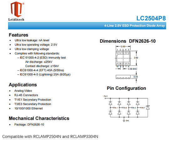
3.3V normal signal and power protection single way
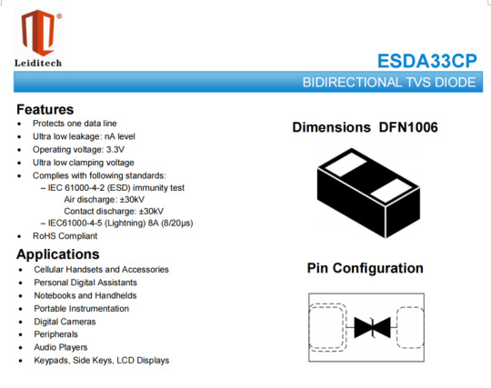
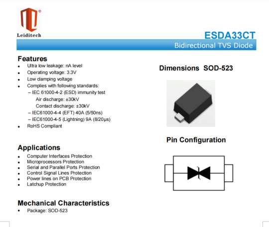
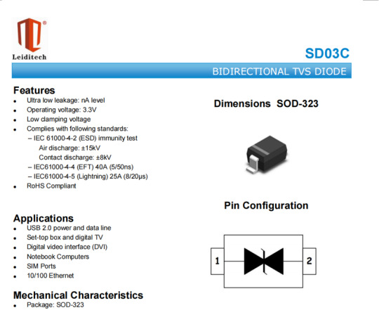
The application of 3.3V is relatively extensive, so according to the number of protection channels, the simplest and most easy to use is ESDA33CP 0402 can be applied to any ordinary 3 that needs protection 3V IO, contact discharge and air discharge are both 30KV. The device also has ESDA33CT SOD-523 and SD03C SOD-323, for some applications with high power requirements, Leiditech provides SMBJ3.3CA , also guarantees low leakage and surge protection.
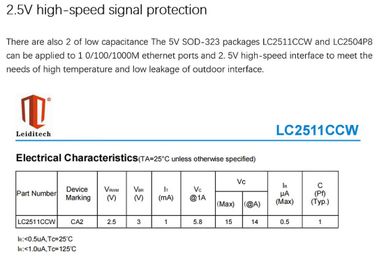
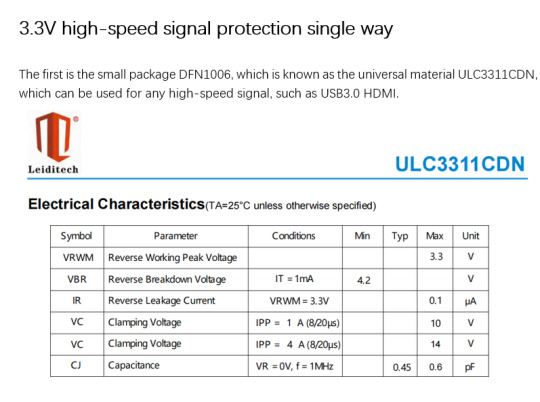
3.3V high-speed signal protection single way
The first is the small package DFN1006, which is known as the universal material ULC3311CDN, which can be used for any high-speed signal, such as USB3.0 HDMI.

If you’d like to learn more or have any questions, don’t hesitate to reach out:
Visit us at [en.leiditech.com] #ESDProtection #Leiditech #CircuitDesign #ElectronicsDesign #LowVoltage #HighSpeedDesign #USB3 #HDMI #IoT #SmartCities #EmbeddedSystems #HardwareDesign #SignalIntegrity #ElectrostaticDischarge #TechInnovation #SurgeProtection
0 notes
Text
DO-218AB Packaging Z5W27V Series TVS Domestic Replacement
1. Applications such as Z5W27V
These materials are mainly used for overvoltage protection in electronic systems and belong to the TVS product series of car regulations.
For example:
1) Automotive electronic systems
2) Commercial Electronic Systems
3) Industrial Electronic Systems
4) Used for communication, controllers, measuring instruments, etc
2. Why apply Z5W27V, etc
1) The excellent clamping voltage characteristics protect the electronic system from any type of surge, such as Load dump LOAD DUMP.
2) High surge power that can withstand the ability to absorb load dumping surges.
3) Can absorb steep surges.
3. Which ones, such as Z5W27V, are out of production
A website found that Z4W27V/Z5W27V, Z5W27VC, Z5W37V,/Z6W27V/Z8W27V, and Z8W37V have been discontinued.
4. Shanghai Leiditech SM5S/SM8S can replace the Z5W27V series products
The Shanghai Leiditech DO-218AB series SM5S/SM8S is mainly used to protect electronic equipment from damage caused by high or low voltage.
SM5S/SM8S TVS is widely used for overvoltage protection and electrostatic discharge protection in circuits. Its main functions are as follows:
1) Overvoltage protection: When there is a sudden change or high voltage in the circuit, TVS can quickly respond and guide excess energy to the ground to protect subsequent electronic components from damage caused by high voltage. This helps to prevent damage to components such as circuit boards and IC chips.
2) Electrostatic discharge protection: When human static electricity or other external static power sources come into contact with electronic devices, it may cause an increase in transient voltage, thereby causing damage to the equipment. TVS can provide a low resistance path to quickly guide electrostatic energy to the ground, protecting equipment from damage caused by electrostatic discharge.
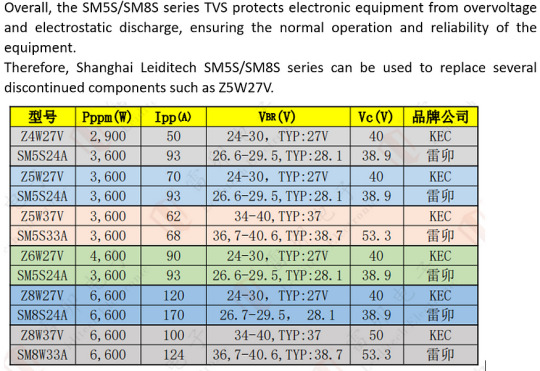
In the above table, the same sample color indicates a comparison between KEC and Shanghai Leiditech of the same model
It can be seen that the corresponding models with the same Pppm in the same color have higher current, lower Vc, and higher power for Shanghai Leiditech.
For example:
SM5S24A replaces Z4W27V, the Ipp of Leiditech is 93A, Z5W27V is 50A, the Vc of S5S24A is 38.9V, and Z5W27V is 40V,
SM5S24A replaces Z5W27V, the Ipp of Leiditech is 93A, Z5W27V is 70A, the Vc of S5S24A is 38.9V, and Z5W27V is 40V,
SM5S33A replaces Z5W37V, the Ipp of Leiditech is 68A, Z5W27V is 62A, and the Vc of S5S33A is 53.3V,
SM5S24A replaces Z6W27V, the Ipp of Leiditech is 93A, Z5W27V is 90A, the Vc of S5S24A is 38.9V, and Z6W27V is 40V,
SM8S24A replaces Z8W27V, the Ipp of Leiditech is 170A, Z8W27V is 120A, the Vc of SM8S24AA is 38.9V, and Z8W27V is 40V,
SM8S33A replaces Z8W27V, the Ipp of Leiditech is 124A, Z5W27V is 100A, the Vc of SM8S33A is 53.3V, and Z8W27V is 50V,
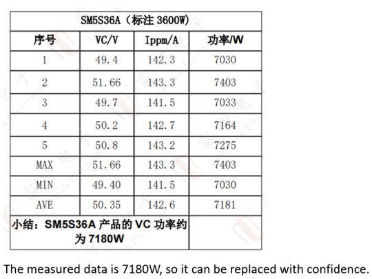
In addition, referring to the current, Shanghai Leiditech seems to be able to replace high power with labeled low power. For example, why can SM5S24A replace Z6W27V, where Z6W27V is 4600W and SM5S24A is 3600W.
In fact, the measured power data of the Shanghai Leiditech SM5S series are much higher than those indicated in the specifications.
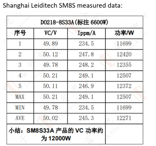
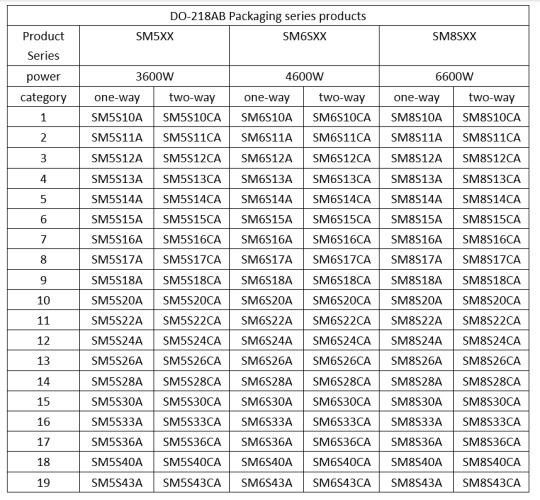
3. Shanghai Leiditech DO-218AB packaging can be made into the following models:
Shanghai Leiditech focuses on the electromagnetic compatibility design of electronic products, and the interface protection of electronic products requires overvoltage protection devices. Many engineers are aware of the need to use protective devices, but due to improper selection or failure to follow the design principles of ESD circuit PCB, the product fails static or EMC testing, wastes manpower and financial resources through multiple product validation tests, and causes product delays or over design, resulting in cost pressure.
Leiditech Electronics provides customers with electromagnetic compatibility EMC design services, providing laboratory testing for free. We aim to efficiently and conveniently complete the design for our customers. We hope that more customers can quickly pass EMC’s projects and improve product reliability as much as possible.
Leiditech Electronic Electromagnetic Compatibility Laboratory provides free testing, peripheral electrostatic protection reference circuits, and domestic certification documents.
If you’d like to learn more or have any questions, don’t hesitate to reach out:
Visit us at [en.leiditech.com]
#TVSdiodes #SurgeProtection #AutomotiveElectronics #IndustrialElectronics #Leiditech #EMCDesign #OvervoltageProtection #ElectrostaticProtection #MadeInChina #Z5W27VReplacement #ElectronicsProtection #SM5S #SM8S #DO218AB #ElectronicComponents #ESDProtection #EMClab #EngineeringInnovation
0 notes
Text
ESD protection method, I’ll take action
1、 Why does the equipment often need to be repaired
Failure to provide ESD (electrostatic discharge) protection may cause potential harm to electronic equipment and components. The following are some possible issues that may arise if ESD protection is not implemented:
1) Component damage: Electrostatic discharge may cause damage or complete failure of electronic components. This may cause equipment malfunction, affect its performance, or result in the need to replace components.
2) Data loss: If electrostatic discharge directly acts on storage media (such as hard drives, flash drives), it may cause data loss or damage. This may lead to information loss, file damage, or inability to access storage devices properly.
3) Frequent malfunctions: Electrostatic discharge may cause brief equipment malfunctions or crashes. This may lead to frequent downtime, increased maintenance costs, and decreased production efficiency.
4) Product quality degradation: If appropriate ESD protection is not taken during the manufacturing or assembly process, electrostatic discharge may lead to a decrease in product quality. For example, in the semiconductor manufacturing industry, electrostatic discharge may cause surface defects on chips, thereby affecting the reliability and performance of products.
5) Cost increase: Repairing or replacing equipment or components damaged by electrostatic discharge may require a significant amount of time and money. In addition, the lack of appropriate ESD protection may require the implementation of additional quality control measures and the addition of testing processes on the production line, thereby increasing costs and workload.
Therefore, in order to protect electronic equipment and components from the impact of electrostatic discharge, it is very important to carry out appropriate ESD protection. This includes the use of anti-static equipment (such as gloves, wristbands, etc.), suitable workbench and flooring materials, appropriate packaging and storage methods, etc.
2、 Structural protection
1) The most important thing in structure is to avoid gaps. If there is no way to minimize gaps, because once there are gaps, there will be
Possible breakdown of air discharge.
2) It is best to use a material for the shell, with overlap between the upper and lower covers. If production allows, sealant should be used as much as possible.
3) When gaps appear in the product structure, keep sensitive signal wiring harnesses and components away from the gaps.
3、 Protecting ESD from the circuit
On the schematic diagram, ESD prevention is mainly from the perspective of conduction, and the main methods include “dredging” and “blocking”.
1) The so-called “dredging” is to quickly bypass the transient interference generated by static electricity to the ground. The main devices include capacitors, TVS transistors, and varistors.
2) The so-called “blocking” refers to blocking interference through resistors. Of course, if the resistance is too small, it may not be effective. If the resistance is too large, it may affect signal quality. Therefore, “blocking” can only serve as an auxiliary function, adding to the icing on the cake.
1. ESD protection first move — capacitance
The first thing that engineers think of when they see ESD protection is capacitors. Why choose capacitors? Cheap, cheap, cheap. Easy to use, easy to use, easy to use. Its advantages are obvious. Choosing a suitable capacitor is once and for all, and it can also suppress interference and resist interference. It’s really a piece of cake. But capacitors are not omnipotent, high-speed signals cannot be used, and large surges cannot solve the problem. It is uncertain how many kV ESD protection capacitors can withstand, and currently they are conceptually usable.
2. ESD protection second move — TVS ESD tube
TVS (Transient Voltage Suppressors) diode is a new type of high-efficiency circuit protection component invented on the basis of Zener diode technology, also known as TVS transistor, transient voltage suppression diode, transient suppression diode, transient voltage suppressor, avalanche breakdown diode, etc. It can be divided into unidirectional and bidirectional. When the two ends of a TVS diode are subjected to instantaneous high-energy shocks, it changes the impedance value between the two ends from high impedance to low impedance at a speed of ns level to absorb an instantaneous large current, clamp the voltage at both ends to a predetermined value, and protect the precision components from the impact of transient high-voltage spikes. TVS mainly focuses on its reverse off state voltage, breakdown voltage, pulse peak current, forward conduction voltage, etc.
3. ESD protection third move — varistor
The resistance material of the varistor is ZNO, which is mainly used to suppress overvoltage protection circuits and limit the voltage within a safe range. When the voltage at both ends of the varistor is less than its voltage, the varistor is equivalent to an insulation resistance of several hundred megaohms or higher. When an overvoltage greater than the voltage is applied at both ends of the varistor, the resistance of the varistor rapidly decreases, leading to the rapid conduction of charges and effectively protecting other devices in the circuit. The varistor adopts the principle of physical absorption, so every time it passes through ESD protection, it will be injured, which can be said to be the desperate Sanlang in ESD protection. The response time is generally at the US level, slower than TVS tubes, but relatively cheaper.
I hope the above tips can help you.
Shanghai Leiditech Electronics provides a variety of packaged and high-power ESDs to meet customer needs.
The EMC product categories of Shanghai Leiditech are as follows:
Shanghai Leiditech focuses on electromagnetic compatibility design of electronic products. Overvoltage protection devices are required for electronic product interface protection. Many engineers are aware of the need for protection devices, but due to improper selection or failure to design according to ESD circuit PCB design principles, the product fails static or EMC testing, wastes manpower and financial resources, and delays the product’s launch. Alternatively, excessive design increases unnecessary costs.
Leiditech Electronics provides customers with electromagnetic compatibility EMC design services, providing laboratory testing for free, efficient and cost controlled design. We strive to quickly pass EMC projects and improve product reliability.
Leiditech Electronic Electromagnetic Compatibility Laboratory provides free testing, peripheral electrostatic protection reference circuits, and domestic certification documents. Contact person Hu Gong 18016225001.
If you’d like to learn more or have any questions, don’t hesitate to reach out:
Visit us at [en.leiditech.com]
#ESDProtection #TVSdiode #Varistor #CircuitProtection #EMCDesign #StaticDischarge #Leiditech #ElectronicsReliability #ElectromagneticCompatibility #PCBDesign #SurgeProtection #AutomotiveElectronics #IndustrialSolutions #ElectrostaticDischarge #MadeInChina #FreeTesting #ZenerDiode #TVSsolution #EMClab #SmartDesign #PCBProtection #ElectronicComponents
0 notes