
Don't wanna be here? Send us removal request.
Statistics
We looked inside some of the posts by pgphysicalcomputing and here's what we found interesting.
Average Info
Notes Per Post
0
Likes Per Post
0
Reblog Per Post
0
Reply Per Post
0
Time Between Posts
7 days
Number of Posts By Type
Text
6
Photo
2
Last Seen Tumblr Blogs


Fun Fact
In 2020, 27% of US Tumblr users had an annual household income of over $100,000.
Text
Final Project
Google Drive link:
https://drive.google.com/drive/folders/1zSZ-e4LBA1PKyKbaP7zTlJ65zkoJpR1G?usp=sharing
My final Project was a culmination of 3 main stages and with a bonus of the 4th stage if it could be done.
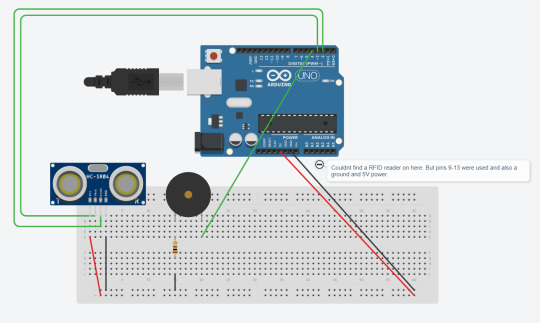
1st stage: Ultrasonic Sensor and Buzzer
2nd stage: Addition of the RFID Reader
3rd stage: Addition of a button (Completed but didnt work)
4th stage: Show time left on a display (not completed)
Additional parts needed:
Ultrasonic sensor, buzzer and RFID
Eleven Male to Female wires (seven to RFID, four to Ultrasonic)
Two Male to Male wires
100 Ohm Resistor
Button
Button
Five Male to Male wires
10k Ohm resistor
How I went about creating it:
I started off with the base of the Ultrasonic Sensor and buzzer setup:

I was happy with this as stage one and was excited to increase its complexity further.
I then added a RFID reader to allow for the user to pause the intruder detection for a certain amount of time allowing them to enter and leave without the buzzer going off.

This was my initial idea now complete but I wanted more, I wanted to simulate that the RFID was the entrance pass and to not be used as the Exit too. Therefore I added a button to be an overide from the inside and allow the user to leave without the buzzer going off.

I ran into some problems with the button as I couldnt figure out which direction it needed to face and after trying to fix the issue it made problems with the rest of the arduino. The code I had written also didnt work with my new addition and meant that the button wasnt behaving as I had expected it too. I believe if I had more time I would have been able to fix the issues and get the button working and allow the user to have two different ways of entering and exiting.
Video displaying functionality:
https://imgur.com/a/uMHQSEl
Circuit Diagram:
Technical Description:
RFID: The RFID component creates a magnetic field waiting for a card or tag to come into the vicinity, if one does a voltage is induced in the cards antenna coil. This then gives power to the card allowing it to return a signal to the RFID reader.
Ultrasonic Sensor: The sensor sends out a burst of ultrasound via the trig pin and the echo pin is what picks up any ultrasound waves that return, the width of the wave that returned defines the distance that the wave travelled and as it went to and from the sensor, halving that value gets the actual distance of the object from the sensor.
Button: The button has two states, LOW or 0 and HIGH or 1. When it is Low the button doesnt complete the curcuit and therefore doesnt trigger anything else but when the button is High it completes the curcuit and allows the power to pass through.
Buzzer: When the Tone function is called it tells the board, firstly, what pin the buzzer is on, and secondly what frequency the buzzer should play. Adding a delay in a loop function to the buzzer means that it can make it seem like its playing on repeat.
Code: (Includes commented out code for the button)
#include <SPI.h> #include <MFRC522.h>
#define echoPin 2 // attach pin D2 Arduino to pin Echo of HC-SR04 #define trigPin 3 //attach pin D3 Arduino to pin Trig of HC-SR04 #define buzzerPin 4 //attached buzzer to pin 4 #define RST_PIN 9 //part of the RFID #define SS_PIN 10 //part of the RFID #define NEW_UID {0xDE, 0xAD, 0xBE, 0xEF}
//loads variables from the .h file MFRC522 mfrc522(SS_PIN, RST_PIN); MFRC522::MIFARE_Key key;
//defines ultrasonic variables long duration; // variable for the duration of sound wave travel int distance; // variable for the distance measurement bool foundCard = false;
//button variables //const int buttonPin = 6; //int buttonState = 0;
void setup() { //RFID Serial.begin(9600); // Initialize serial communications with the PC while (!Serial); // Do nothing if no serial port is opened (added for Arduinos based on ATMEGA32U4) SPI.begin(); // Init SPI bus mfrc522.PCD_Init(); // Init MFRC522 card Serial.println("Warning: this example overwrites the UID of your UID changeable card, use with care!");
// Prepare key - all keys are set to FFFFFFFFFFFFh at chip delivery from the factory. for (byte i = 0; i < 6; i++) { key.keyByte[i] = 0xFF; } //Ultrasonic Sensor pinMode(trigPin, OUTPUT); // Sets the trigPin as an OUTPUT pinMode(echoPin, INPUT); // Sets the echoPin as an INPUT
//button //pinMode(buttonPin, INPUT); } void loop() { if(foundCard == false) { //ultrasonic sensor // Clears the trigPin condition digitalWrite(trigPin, LOW); delayMicroseconds(2); // Sets the trigPin HIGH (ACTIVE) for 10 microseconds digitalWrite(trigPin, HIGH); delayMicroseconds(10); digitalWrite(trigPin, LOW); // Reads the echoPin, returns the sound wave travel time in microseconds duration = pulseIn(echoPin, HIGH); // Calculating the distance distance = duration * 0.034 / 2; // Speed of sound wave divided by 2 (go and back) // Displays the distance on the Serial Monitor Serial.print("Distance: "); Serial.print(distance); Serial.println(" cm");
if(distance < 15) { tone(buzzerPin, 1000, 50); }
//BUTTON //buttonState = digitalRead(buttonPin); //if(buttonState == LOW) //{ //Serial.println("Button if statement"); //foundCard = true; //}
//RFID // Look for new cards, and select one if present if (mfrc522.PICC_IsNewCardPresent() && mfrc522.PICC_ReadCardSerial() ) { String content= ""; Serial.println("I found a card"); // Dump UID Serial.print(F("Card UID:")); for (byte i = 0; i < mfrc522.uid.size; i++) { Serial.print(mfrc522.uid.uidByte[i] < 0x10 ? " 0" : " "); Serial.print(mfrc522.uid.uidByte[i], HEX); content.concat(String(mfrc522.uid.uidByte[i] < 0x10 ? " 0" : " ")); content.concat(String(mfrc522.uid.uidByte[i], HEX)); } Serial.println(); content.toUpperCase(); if(content.substring(1) == "67 0A 6E B5") { Serial.print("Access Authorized"); foundCard = true; } } } else { Serial.println("Else Statement"); delay(10000); foundCard = false; } }
Evaluation:
I ran into some problems trying to get the first experimental stage added to the curcuit, still unsure as to why it happened but if I had given myself some more time I could have figured out how to get it to work. I left out the last stage by default as I felt I was using too many pins at this point in time for me to understand how to get a full display working. I know how it would be done but actually learning and implementing it would have taken more time than I had left.
I loved creating this build and when it came together in its first stages it properly made me smile about completing something I didnt think I could have actually done.
I feel like this can be used on a larger scale for many different uses, such as; Actual home intruder detection, or especially the Ultrasonic sensor being used as a way to notify a car driver if they are getting close to an object when reversing.
I learnt that electronics and physical computing is a lot of fun, especially when something you didnt think would works actually comes together and works as intended.
0 notes
Text
Final Idea
After realising my intial idea of the bowling game automation system was far to complex for the time left and my ability to create what I wanted, I decided to go back to the workshop experiment I did with the ultrasonic sensor and decided to plan out how I could make use of this and what it could become.
I decided on a home intruder detection system that notifies with a sound if something has gone through the sensor, I want to add several other layers ontop that extend the project out and make it a bit more interesting.
I have come up with a couple things to add, one of these will be a way to stop the buzzer from buzzing when something is in the way, kind of like a overide to allow entrance infront of the sensor. Secondly I would like there to be a timer that shows how long is left before the sensor is reactivated and finally a way to shut off the sensor from a 2nd side, maybe a button may work.


0 notes
Text
First ideas for final project
The first idea i had for my final project was to create a mechanism that attached to one of my favourite toys of all time to make it more automated than it originally was. This toy being Mickey Mouse’s Big Time Bowling.

My idea was to add a system that moves the Pin Setter, which is the large yellow structure at the left side, up and down automatically after it had sensed a ball pass through a sensor, to allow for the player to add pins back in to the pin setter. The idea was to also add a way for the ball to automatically be sent back to the start area to be used again next throw.
After a couple weeks of brain storming how I was going to go ahead with this I decided it required too many components that I didnt have any way to aquire, whether that was due to time or monetary reasons.
In my calculations I would have needed three servos in total and with only one given in the starter kit it meant it wasnt feasible to continue. I also would have needed access to materials to create the extra parts for the mechanism and again I couldnt get hold of this because of monetary reasons.
0 notes
Text
Week 5
Free Form Workshop
I choose to use the Ultrasonic Sensor and a buzzer to create a buzz whenever the sensor detected something within a certain distance.
Parts used:
Ultrasonic sensor, Buzzer, Arduino Uno R3 board, breadboard, 100Ohm resistor, two male to male wires, four male to female wires.
Layout:

Curcuit diagram:

How it works:
The ultrasonic sensor has 4 pins on it. From left to right; “VCC”, “Trig”, “Echo”, “Grnd”. The first pin VCC is connected to the 5V and allows the senor to get power, Trig is the pin that sends out the ultrasonic wave and is the OUTPUT. Echo is the pin that recieves the sound wave back from any objects that were hit by the wave and finally Grnd is connected to ground.
Trig sends out a sound wave and Echo picks up a reply if anything was in the path. The code then checks a distance and if its less than that it will set the buzzer off. Pin 4 for the buzzer is sent a signal and it travels through the buzzer, through the resistor and to ground.
Code:
#define echoPin 2 // attach pin D2 Arduino to pin Echo of HC-SR04 #define trigPin 3 //attach pin D3 Arduino to pin Trig of HC-SR04
#define buzzerPin 4 //attached buzzer to pin 4
// defines variables long duration; // variable for the duration of sound wave travel int distance; // variable for the distance measurement
void setup() {
//Ultrasonic Sensor pinMode(trigPin, OUTPUT); // Sets the trigPin as an OUTPUT pinMode(echoPin, INPUT); // Sets the echoPin as an INPUT } void loop() {
//ultrasonic sensor // Clears the trigPin condition digitalWrite(trigPin, LOW); delayMicroseconds(2); // Sets the trigPin HIGH (ACTIVE) for 10 microseconds digitalWrite(trigPin, HIGH); delayMicroseconds(10); digitalWrite(trigPin, LOW); // Reads the echoPin, returns the sound wave travel time in microseconds duration = pulseIn(echoPin, HIGH); // Calculating the distance distance = duration * 0.034 / 2; // Speed of sound wave divided by 2 (go and back) // Displays the distance on the Serial Monitor Serial.print("Distance: "); Serial.print(distance); Serial.println(" cm");
//checks if the distance was less than 15cm (can be changed to what ever distance needed)
if(distance < 15) { tone(buzzerPin, 1000, 50); }
}
Evaluation:
Everything worked well on this one, I didnt run into any problems and it was fun to understand that I could interact with a buzzer in that way.
This was the first experiment where I felt like I had actually created something that worked and it was a nice feeling to get it to work.
0 notes
Photo

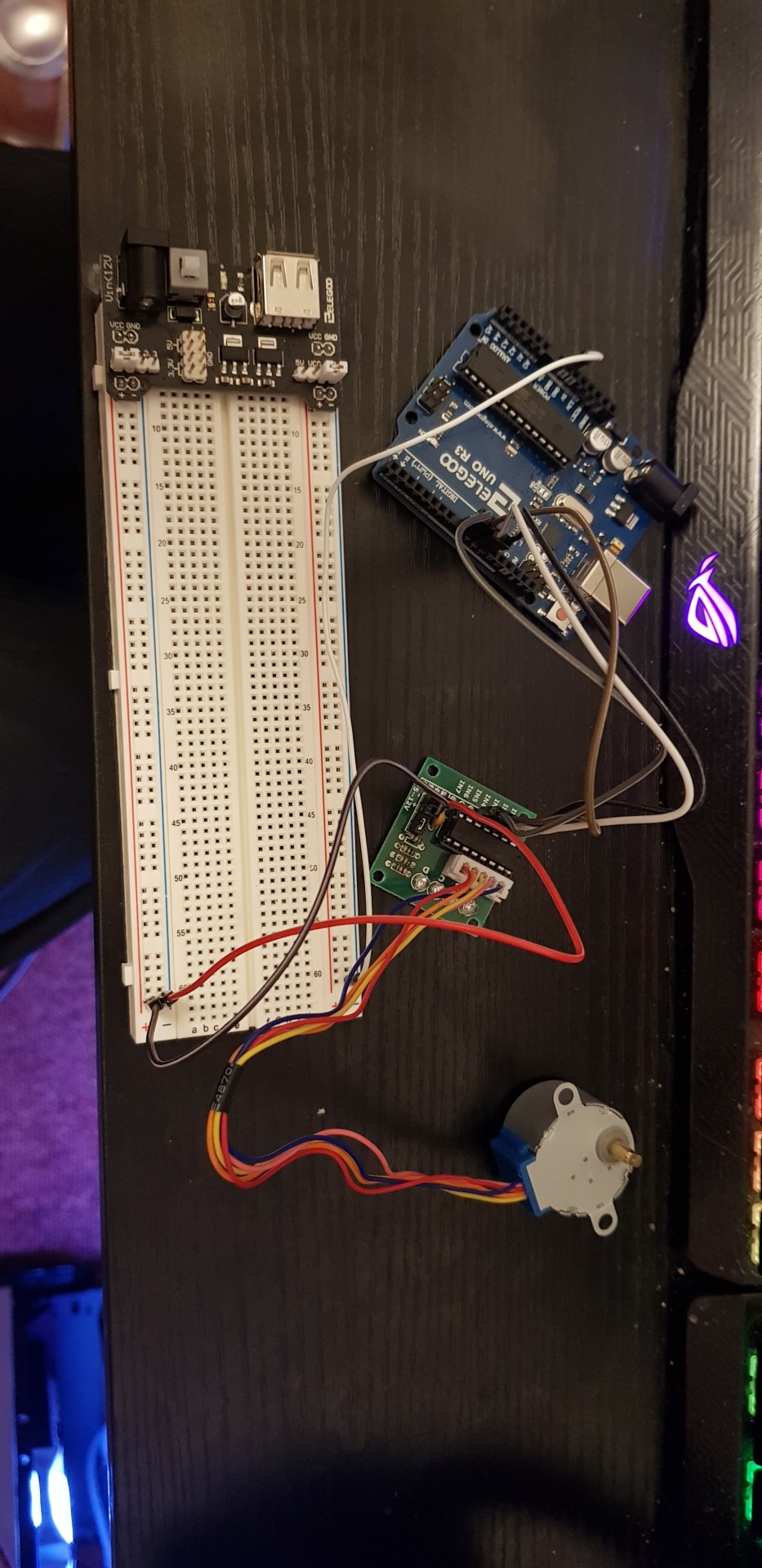
Week 4 - Stepper Motor
Learning how to control a Step Motor. The power supply module connected to the breadboard allowed for power to come directly from a socket, this was required to power the step motor. The step motor was connected to stepper motor driver module and this took power from the breadboard (5V), the stepper motor driver module was also then connected to the UNO R3 controller board, it was connected with the use of male to female wires rather than the normal dual male wires, also ground was added from the UNO board to the breadboard to complete the circuit. The controller board was used to run code that made the stepper motor move.
NEVER CONNECT THE ARDUINO’s 5V TO THE CONTROLLER.
Setup:

How it works:
The external power supply feeds into the stepper controller with power and a ground, with a seperate ground coming from the arduino board, four wires are connected to the IN1-4 pins also from the arduino, this allows the motor to be controlled, the motor has a connector that connects to the other side of the stepper controller, this is keyed and can only go in one way.
Inside the stepper motor is a gearing system of 4 sets of cogs, firstly 32/9, then 22/11, then 26/9, and finally 31/10. This gives it a 64/1 gear ratio.
The Stepper Motor can have a total of about 2038 steps per one revolution of the motor which allows for precise control.
Code:
#include <Stepper.h>
const int stepsPerRevolution = 200; // change this to fit the number of steps per revolution const int rolePerMinute = 2; // Adjustable range of 28BYJ-48 stepper is 0~17 rpm
// initialize the stepper library on pins 8 through 11: Stepper myStepper(stepsPerRevolution, 8, 10, 9, 11);
void setup() { myStepper.setSpeed(rolePerMinute); // initialize the serial port: Serial.begin(9600); }
void loop() { // step one revolution in one direction: Serial.println("clockwise"); myStepper.step(stepsPerRevolution); delay(500);
// step one revolution in the other direction: Serial.println("counterclockwise"); myStepper.step(-stepsPerRevolution); delay(500); }
Problems I had:
For me personally my stepper motor would get very hot to touch and for that reason I didnt have it setup for long. I am unsure what the problem was and had no fix at the time of doing the experiment. It did work though.
0 notes
Text
Week 3
Servo
This week we learnt how to attach and control a servo motor. This has many uses, for instance servos can be used to control RC airplane control surfaces, a marble maze labrynth, and the opening and closing of entrances and exits.
In the lesson we connected up the servo to the arduino board with a varaible resistor in the form of a potentiometer, this allowed the servo to be controlled by the change in temperature. An extension of this was to control the servo with a light dependant resistor.
Parts needed to run just the servo:
Servo, Arduino board, three males to male wires, potentially an outside power supply depending how much voltage the servo uses (>250mA).
Parts needed for Potentiometer:
Potentiometer, more males to male wires.
Parts needed for LDR:
Light dependant resistor, more male to male wires.


How it works:
The servo can rotate 90 degrees each way allowing 180 degrees of movement in the code for just the servo we see it will sweep through 0-180 degrees and then return to 0 after a small delay. This is where I ran in to trouble as the servo would turn maybe max 10 degrees at a time, meaning I couldnt feasibly complete the other two tasks.
The potentiometer adds a new level of function to the servo allowing it to read a temperature and for it to rotate the servo to a specific degree.
The LDR does the same but dependant on how much light is shining on the resistor.
Code for just Servo:
#include <Servo.h>
int servoPin = 9; Servo servo; int angle = 0; // servo position in degrees
void setup() { servo.attach(servoPin); }
void loop() {
// scan from 0 to 180 degrees for(angle = 0; angle < 180; angle++) { servo.write(angle); delay(15); }
// now scan back from 180 to 0 degrees for(angle = 180; angle > 0; angle--) { servo.write(angle); delay(15); } }
Code for Potentiometer:
#include <Servo.h> // add servo library
Servo myservo; // create servo object to control a servo
int potpin = 0; // analog pin used to connect the potentiometer int val; // variable to read the value from the analog pin
void setup() { myservo.attach(9); // attaches the servo on pin 9 to the servo object }
void loop() { val = analogRead(potpin); // reads the value of the potentiometer (value between 0 and 1023) val = map(val, 0, 1023, 0, 180); // scale it to use it with the servo (value between 0 and 180) myservo.write(val); // sets the servo position according to the scaled value delay(15); // waits for the servo to get there }
Code for LDR:
#include<Servo.h> int lightval; int lightpin=A0; int tm=100; int servopin=3; Servo myservo; int angle; void setup() { Serial.begin(9600); pinMode(lightpin,INPUT); myservo.attach(servopin); pinMode(servopin,OUTPUT); }
void loop() { lightval=analogRead(lightpin); //Reads LDR value Serial.println(lightval); //Prints that value delay(tm); //delay adjustable
angle= lightval/5; //calculates the angle myservo.write(angle); //sets the servo to that angle Serial.println("angle is"); Serial.println(angle); //outputs in the serial the angle
}
Evaluation:
This experiment was a bit of a let down for me as no matter what i tried I couldnt get the servo to move more than a couple of degrees before returning back to its original position. In the future I would have tried to trouble shoot it more to see if it was a problem I could have sorted or a problem with the servo itself.
0 notes
Text
Week 2
Blinking LED
First week was an introduction to physical computing and understanding electronics. We started with blinking an LED on the Arduino.
All you need is the arduino board and the USB cable for power.
Setup:
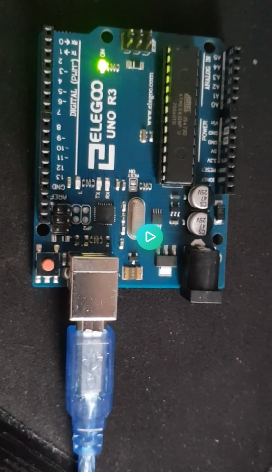
Video:
https://imgur.com/sgbYeD7
code:
// the setup function runs once when you press reset or power the board void setup() { // initialize digital pin LED_BUILTIN as an output. pinMode(LED_BUILTIN, OUTPUT); }
// the loop function runs over and over again forever void loop() { digitalWrite(LED_BUILTIN, HIGH); // turn the LED on (HIGH is the voltage level) delay(1000); // wait for a second digitalWrite(LED_BUILTIN, LOW); // turn the LED off by making the voltage LOW delay(1000); // wait for a second }
The simplest thing to setup with an arduino, normally already programmed on to the board.
0 notes
Photo

Thematic Infographic
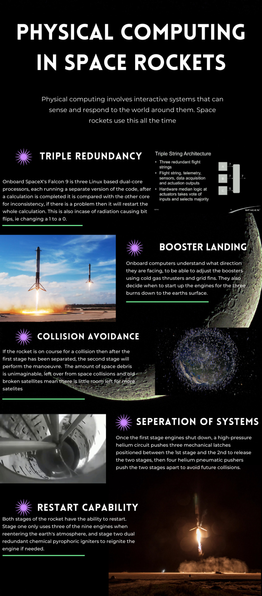
I chose to go with Physical computing in space rockets because it is something that I am extremely passionate about, I am always amazed at the work that goes into getting a rocket up into space and even more so being able to bring it back down and land them with little to no human interaction. After a little bit of research, I did not find much of quantifiable data that would have allowed me to have percentages. So, I focused on the core systems of the rocket and the stats of the most popular rocket around in the Falcon 9.
(The stats page doesnt look as sharp as I didnt realise my chrome addon Dark Reader made the text unreadable when i downloaded it. I had to screen grab it instead.)
Links to resources:
https://www.spacex.com/vehicles/falcon-9/
https://www.spacex.com/media/Falcon_Users_Guide_082020.pdf
https://www.wikiwand.com/en/Falcon_9_Full_Thrust
https://space.stackexchange.com/questions/9243/what-computer-and-software-is-used-by-the-falcon-9#
0 notes