
Don't wanna be here? Send us removal request.
Statistics
We looked inside some of the posts by quicktothematmobile and here's what we found interesting.
Average Info
Notes Per Post
3
Likes Per Post
2
Reblog Per Post
0
Reply Per Post
1
Time Between Posts
3 months
Number of Posts By Type
Text
15
Photo
2
Last Seen Tumblr Blogs


Fun Fact
In 2020, 27% of US Tumblr users had an annual household income of over $100,000.
Text
Electrics, v3!
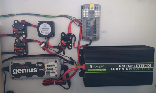
I wasn’t too happy with the last electrical switchboard, and having just bought an inverter I took the opportunity to redo it all.
I’d used a trailer plug and socket on the previous board to connect that board to the camper circuits, but it was a tight fit under the seat and I’d thought about trying to move it behind one of the seat backs.
I’d also added an Arduino + LCD display to run the power monitoring and control, but that failed almost immediately when I accidentally shorted out a MOSFET switch, so I abandoned that until I could rework it.
In the end it was easier to just get rid of the board all together and install everything on the wall behind the set back.
On the left side of the bench seat (not pictured) is where the wiring comes out of the cable channels. It’s still very messy, which is why I’m not showing photos. :D I will tidy it up, honest. There’s also a ground rail, which is attached to the vehicle chassis, to the leisure batteries, to various devices, and also via the thick black cable in the photo to the inverter.
On the right side (pictured) are the devices and fuses and all the switches that we need access to. The two large switches/breakers on the left are the lines in from the starter and leisure batteries. The starter battery is now wired in via a VSR, so it connects automatically now. Both batteries and the charger are connected together at the master power switch in the middle.
(If I ever get around to installing the solar panel and MPPT charger, that will go in here.)
The other side of that master switch goes to the fuse block and the inverter. The cabling out from that fuse block goes back to the left side, where a terminal block connects back to the van wiring.
I tested the inverter’s load while switched off - it consumes less than 5mA, so I’m okay with having it connected when the master power is on. However, if it’s switched on with no load, it consumes 1.4A, so that’s something to avoid. The inverter has a remote on/off switch and indicator, I’m not sure where to install that. But the mains power isn’t done yet anyway (space at top right of that panel!), so will cross that bridge later.
In getting rid of the previous panel, I’ve lost the other switches that were on that board. The charger switch isn’t an issue - if there’s power to the charger then it should charge! Having switches on some of the fuse-block outputs was nice (switch off the fridge, for example), but will live without those for now.
Apart from the one thick black negative cable to the inverter (and then also to the charger and the VSR), all the wiring here is all +12V. That helps keep it all neat. But I was concerned about having the high current +12V connectors exposed, so I bought some liquid electrical tape - that’s the red gunk you can see on the terminals of the breakers. I’ve put on 3 layers so far, but my multimeter still reads voltage through the insulation, so either it doesn’t work, or I’m going to have to keep applying more layers.

With a hole cut in the seat back, we have easy access to the master switch and the fuses, and also can get to the other switches and the charger too.

I’ll probably put a magnet at the top of that panel to hold it in.
Still to do: Arduino to monitor current and voltage levels. AC breaker box, with or without the option of inverter input.
1 note
·
View note
Text
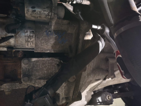
Replacing the starter motor
2012 Ducato 250 JTD.

So the starter was only working intermittently. When it would turn the motor over it would start (although it seemed a bit weak, given the battery is fairly new), but occasionally it would just click (solenoid noise) and not turn. I'd give the starter and solenoid a bash with a rubber mallet, rock the van a little in gear, then try again, and it would start, but it needed to be fixed.
Gave Augustin (https://augustin-group.de/) a ring, they’ve got a few replacement models and they’ve always been good on the phone, recommending which brands to go with, and got a new one from ATL for 180€.
Went to my local DIY workshop and put the van up on a hoist. Now that I’ve seen how to do it, I could do it without it lifted, but I’m happy to spend 25€ to make the job that much easier. The starter motor is located just behind the radiator, it’s easily reached on my van. I saw one report that said there was plastic shrouding under the motor which needs to be removed, but there was none of that on mine!
The replacement itself is straightforward.
1 - disconnect the battery.
2 - disconnect the main power cable from the starter (13mm socket. I could have used a short tube spanner for this - the nut is located within a plastic shroud, which I had to cut open to get my socket to fit inside it) and the solenoid cable (10mm socket). Remember, that main cable is always live and can carry plenty of amps, so don’t forget step 1!

3 - remove the 3 bolts holding the starter on (13mm socket). A bit of WD40 and the bolts all came out easily. The top one is a little tricky to get to, but no drama with a socket wrench.
4 - put the new motor on with the reverse of the above.
Easily done in an hour.
0 notes
Text
Electrics, v2

So the v1 version of the electrics board that my daughter and I whipped up last year was really large and had to come out when I put the bench-seat in, and since then I’ve been looking at getting a new board made up that will fit under the seat. This is what I’ve come up with so far.
Apart from adding in the solar charger and knowing a bit more about what I need to control and switch, the layout went through a few iterations. I wanted to make it obvious, what needs to be done to get power switched on. Originally the wiring for some components was above the board, but I didn’t like that, and have recessed them back under the panel.
Once I’ve tried it all out and tuned the layout a bit, I’m tempted to get it printed on a piece of foam board (can be done online pretty cheap) for the final product. It’s currently sized A3, but I’ll make it a little narrower to fit under the bench easier.
Components
The two heavy-duty power cables (from the starter and leisure batteries) each have a 100A breaker on them.
The cable from the vehicle battery also has a relay, currently just connected to a simple switch, but later to be controlled by an Arduino which will sense the voltage to determine when the alternator is running.
The solar charge controller (not yet installed) is a cheap MPPT controller with a serial connection, so I’ll be logging its activity to see how much power it’s producing.
There’s a Blue Sea Systems fuse block which I really liked the look of, but hasn’t fitted as neatly into the board as I would have liked. I’ve put switches on half the outputs from that, while the other half will be used for stuff that doesn’t need switching (the fuses can still be pulled to turn that stuff off).
There’s a bypass switch that connects power straight through to the fuse block, even if the solar controller isn’t doing so. On the back, the heavy-duty posts of that switch are used as connection points for all the cabling.

There’s a rail on the back for the ground connections. And indicator lights to show where power is available (not yet connected). I think I’m also going to put a terminal block on the back that all the power outputs go through, so that a simple cable loom will run from this to the van cabling. This board sits below a seat, but above the batteries, so it needs to be removable to be able to get to the batteries.
The electronics on the lead to the leisure battery is a WCS1600 Hall Effect sensor which will also attach to the Arduino to measure current flowing to and from the leisure battery.
I may end up putting an LCD display or something on the Arduino, and mounting that on the panel too. But principally the Arduino will be delivering power data to the Raspberry Pi. And I’ll run something up to the driver’s seat to display and control the split-charge relay from there too.
0 notes
Text
Making it official
In order to get the TÜV to certify the vehicle as a camper, I needed to get some more items installed quickly. Most of these aren’t finished, but are advanced enough for their liking. So, as of last week, the Matmobile is officially a campervan! Here’s what been added:
Kitchen

The kitchen’s an Ikea cabinet with a work surface on top, raised to about 90cm to be at the right height. There’s an induction hob, to be used on hook-up only. That’s enough to satisfy the TÜV’s requirement of a permanent stove.
The cupboard doors and drawer have push-locks attached, to stop them opening while driving. I’ve only installed one of the two drawers, with both drawer fronts screwed together on the front of it. That’s so, if I decide to install a sink to the left of the hob, there’ll be enough depth to put it in there.
Ikea chipboard furniture isn’t great for campers - it’s pretty susceptible to damp. But it’ll do as a temporary measure.
Cupboard
A cabinet goes in opposite the kitchen, with the fridge installed at a comfortable height.

There’ll be some nooks cut into both sides of this, and the touch-screen for the Raspberry Pi will go in the right hand side. The front just has some temporary slats to stop stuff falling off the shelves, later there’ll be a nicer front with doors.
There’s a vent in the side of the van, behind the fridge. This will be improved later on, to make sure the fridge’s heat gets vented out there in summer, and piped back into the van in winter. More on that later.
Bench
The bench was originally going to be facing forward, but I changed my mind and put it along the wall, in front of the cupboard.

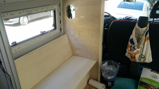
A wall was put up behind the driver’s seat - the hole’s so the driver can see out that window there. There’s a small shelf screwed to the wall, and 3 battens suspended between that wall and the cupboard. Two storage spaces under the bench - on the left the batteries and the electrical wiring, and on the right for other stuff. They’re separated by timber that also supports those battens.
The sheeting here is 8mm poplar ply - a lot lighter than what I made the cupboard and bed out of. I’m still not sure if it’s sturdy enough, maybe I should have gone a little thicker, for the seat at least. The bench seat and back will be upholstered - I got some garden furniture cushions from Ikea today to use temporarily.
Table
The table hooks onto a rail across the front of the van.

It’s a super cheap offcut of ply that I played around with, reinforcing it to straighten it out, and sanding it back as smooth as I could, before varnishing it. It can slide left to right on that rail, and is sized to fit into the gap forward of the kitchen. Here’s it’s over to the left, sitting over the bench.
The rail, with its clips, and the table leg were bought from Reimo.
Later, a book shelf will go along the top of the wall above that window. And some more timber edging will clean up the border between the cab and the van, along with a curtain.
0 notes
Text
21st Century TV (aka Internet)

I see a lot of vans with satellite dishes on the roof, but I haven’t watched satellite TV in years and it seems like a waste to spend so much money on such outdated tech. I also want the van’s IT to be online all the time, so getting some sort of mobile network hub was on my list. So why not get a great Internet connection and use that for TV as well?
Looking at the available technologies, I wanted it to be capable of LTE and HSPA. My budget meant that I was looking for a portable hotspot, and I wanted it to have an external antenna connection. In the end I went with the Huawei E5786, for 150€.

This little beauty has an external antenna connection (MIMO), supports up to 10 connected devices, runs LTE at up to 300Mbps, and can even act as a router over a WiFi connection - so at a campsite or when it’s parked outside my home, it uses the WiFi, rather than the mobile network.
On the downside, it’s not designed to be installed anywhere, so the connectors are all quite small and flimsy ( I’ll have to be sure to install it with good tension relief on the cables), and it will go into standby if no devices are connected, meaning that I need access to the device to switch it back on when it’s needed.
FTS Hennig gave me some advice about antennas, and you can read about MIMO antennas online. Many MIMO antennas put two antennas at 90° to each other (one horizontal and one vertical), and otherwise two separate antennas should be separated by 1 metre or more. MIMO connections will actually use more than one path simultaneously in order to achieve their maximum bandwidth.

A window-mount antenna might be a great option for some vehicles, but I don’t have many suitable windows in my van, and I figured roof-top antennae would give me better omnidirectional coverage. I chose this Panorama LPB low profile antenna.

I got two of these antennae (26€ each), which come with a 5m cable and an SMA plug, as well as the SMA-to-TS9s adapters (15€ each) that I’d need for my hotspot. I sprayed the antennae white, and mounted them at the front and back of the van (see top photo). They’re positioned to hopefully not interfere with any roof-rack I might later install.
Inside, I scraped off some paint to get a good ground connection - the antenna needs a certain amount of flat metal around it (10cm, I think) to work correctly. The antenna is mounted with an adhesive foam pad and some Sikaflex, as well as the screw-thread.

I’ll finish this up with some primer and will then patch the insulation.
Performance

So here’s the results of a simple performance test in Munich, near my place. I ran 3 tests with the speedtest app - one with my phone directly on the LTE network, one with my phone on the hotspot, using its internal antennas, and one using the hotspot and the external MIMO antennas. The results are pretty impressive!
Smartphone LTE: Download 7.30 Mbps, Uploas 1.58 Mbps.
Hotspot alone: Download 16.36 Mbps, Upload 16.18 Mbps.
Hotspot, MIMO: Download 39.67 Mbps, Upload 31.42 Mbps.
This is on the Vodafone network with the “DataGo M” tariff (“Internet Flat mit max. LTE-Speed”).
0 notes
Text
Securing the batteries
The auxiliary batteries weigh a ton, and shouldn’t be able to fly around the van in an accident.

The battery boxes I bought came with some pathetic straps and clips (as pictured above) that were never going to be up to the task. I also bought a cheap timber shelf to use as a frame to stop things sliding around, but the timber is such crap and prone to cracking, I’d have been better off with just a few battens.
While I was cutting and painting steel, I made up a few more plates, and bolted them to M8 tee-nuts in the floor:

Along with a ratchet strap, the batteries aren’t going anywhere now!


A bench seat will be built around these batteries, with electronics and a switch panel hidden under the cushions.
0 notes
Text
Making a bench grinder
So converting the van is a great excuse to buy loads of fun new tools, but still I have to save money where I can. Recently I was making up some steel plates that will support the central section of bed, and I wanted to round off the corners so they won’t hurt anyone. I would have used a bench grinder, but I don’t have one. Or do I...?

Yeah, it’s just an angle grinder, bolted to a block of wood with a couple of brackets. Does the job, though!
youtube
Here’s how those plates ended up:

I tapped an M6 hole in the end of two of them - the bolt sticking up on top locates in the frame of the bed when it’s down to add some more stability. And there’s some rubber sheeting on top.

Hmm, that bolt would probably work just as well put in from the top, and look better too.
And here’s another purpose-built tool, the “mill�� I built to chamfer off some timber. The timber gets slid along the guide and under the router bit.

0 notes
Text
Setting Tee-nuts

I’m fixing furniture to the floor with M8 tee-nuts (Einschlagmuttern in German), which need to be put in from underneath the timber floor plate. I got the van with this Fiat flooring already installed, and it’s cut to be a really good fit in the van, which means it’s really, really hard to get it in and out of the van!

Even a seemingly simple job like lifting it upwards results in that plate getting caught on every little protrusion. There are two plates, that join with tongue-and-groove, and the bed frame is sized to sit only on the plate at the rear. This weekend it was time to lift the plate at the front and set the tee-nuts under it.
I had to clear everything off of the floor plate and remove everything in the van that would get in the way of lifting it (front seats, electrical panels and conduits, end panels on the bed frame, etc.). Thankfully I didn’t have to remove the bed and rear floor plate.
I marked out all the points on the floor where I could conceivably need tee-nuts to fix things. There are several brackets for fixing cabinets to.

There are points for securing the batteries to, as well as points around the edges and along two possible lines where I might later build a raised section around the dining table.

I marked the points and drilled them half-way through before I started. At first I was able to lift the plate only about a foot - that was enough for me to be able to finish drilling the 9mm holes, and get the nuts closest to the doors in place. The ones in the rear left corner and down the left side were way harder and I had to prop the plate up against a bit of timber, then lie on the plate and twist my arm underneath to get the nut in, hoping that my prop didn’t slip out.
Hammering the nuts in was out of the question - the timber is too hard, and there’s not enough access to the bottom and the timber’s not stable enough. So I used the threads of the nuts to pull them in from the top. There were two problems with this method - first, the nuts had a tendency to spin underneath, wrecking the claws that hold them in place, and secondly this was really hard on the threads, wrecking a bolt after only inserting 3-4 nuts.
After trying a bunch of different things, here’s what I found worked best:
- Don’t turn the bolt too fast. Nice and slow on the battery drill up to a torque setting of about 10, then the rest with an allen key.
- Greasing the bolt makes a huge difference - I didn’t wreck any more bolts after I started doing this.
- I used a small thrust bearing on the top of the board to reduce friction there too. Not sure how much that helped, but it can’t have hurt.

With a bit less patience and a bit more brute force, I managed to lift the board up higher, and get underneath to clean out the debris.

Here you can see my patchwork insulation job too.
With the floor plate back in place, I took a bunch of photos to help me find the holes later, once the flooring was covering them, so I have tons of photos like this:

Finally I cut the PVC flooring to size, put it in, and started to fix the brackets on top. On this bracket you can also see the M6 rivet nuts that I’m using.

Here’s the temporary kitchen cabinet, ready to be fixed in place.

Next will be to put the electrics back in place, and then to start work on the full-height cupboard.
0 notes
Text
The Bed
The bed’s across the back of the van, and is a luxurious 160cm wide. It’s about 65cm high, which is low enough not to block the view out the rear windows, and will also allow access to the handle on the rear door (a German safety requirement). Otherwise I’d have been tempted to put it higher, to have more room for storage underneath it (camping chairs are about 70cm wide). Still, at 65cm high, I’ll still be putting a step in to make it easier to get in and out of the bed.
Forward of the bed will be a full-height cupboard on the left, and the kitchen on the right. Those units will stop the mattress etc. from sliding off the bed, but they won’t be attached to the bed - I’m leaving a 5mm gap between the bed and them, and filling that gap with a 10mm expanding foam strip. The bed base also has edging around it to stop the mattress sliding around, or things from falling down the sides.
The cupboard will come out 60cm from the wall, and the kitchen 45cm. The bed has frames that also come out about that far, and a removable piece in the centre. So there’s permanent storage under those two frames (which is also over the wheel arches), and the central section can also be used for storage or, when the bed is removed, for loading bicycles, a motorbike, or other long loads through the van.
I decided to try using aluminium profile to build the bed. I’d not used it before, and wanted to see how it went, before I decided whether to use it for the rest of the furniture or not. Doing some price comparisons online it looked like Easy-Systemprofile were going to be a good cheap option, and they were pretty helpful online as well, taking a look at my sketches and advising me on the best way to do the joints. Here’s the plan I came up with:

The boards on top of this will add some stability, and there are struts in the joints to make the construction more stable in the other directions. The frame is bolted to the floor with 14 angle-brackets and M8 bolts in tee-nuts. The single legs on two corners are at the back of the van to make it easier to slide stuff into the storage areas, whereas the two lengthways beams on the floor will be used to securing loads (bikes etc.) to.
The frame cost me about 400€, and went together and into the van easily enough.

I got some plates that connect to the side frames and support the bridge in the middle, but later decided to make different plates myself, with rubber padding and a bolt to lock the bridge in place.
Multiplex boards were used for the bed base, and cut to fit into the corners of the van.


A mattress was also bought and altered to fit. And I set about installing hinges so that the bridge can be swung up and out of the way. I used a Dremel along a guide to mark out what I needed to remove, then chiseled out layers of timber until it was deep enough. By the time I’d done the 4th one, I felt like I knew what I was doing!

We’d just had some plumbing work done in the bathroom, so I took advantage of the empty room to use it to do all my sanding in.

And then I varnished the timber on our dining-room table.

I haven’t done the best possible job there, but what I’ve learned doing it will help me heaps when it comes to doing the other timber pieces later that are actually going to be visible!
Here it is all put together:


There will be spring-loaded latches at both ends to hold the bridge in the vertical position, so the broom isn’t a permanent fixture. And I’m thinking about installing some drawers under the bed on the left and right, leaving room under them for crates and other gear (cables, outdoor furniture, bbq, etc.).
The sides and end of the storage areas are lined with sealed plywood (Siebdruckplatte) to keep things in place. It’s not super sturdy (4mm), but I’ll see how it holds up.
Once the bed is made up I’ll get a photo of it looking nicer. :) There will finally also be storage nooks, built into the rear pillars and into the side of the cupboard, and another slim cupboard across the top of the wall on the right (the foot).
0 notes
Photo

Showing why I’m grateful for Kat’s patience and tolerance during this project of mine. Also, our kitchen is currently my paint-shop.
0 notes
Text
Disassembling a Bosch PSB 650 RE drill
The spindle lock on my drill doesn’t lock properly any more, which is a problem for this drill with its keyless chuck, so I opened it up to find the problem.
The case says it’s a PSB 650 RE, but from looking at spare-parts diagrams, I think it’s actually a ”Bosch PSB 650-2 / 0603386103”.
First step is to pop off the grip at the back, as it covers some screws:

Then the plastic on top also needs to be popped off:

Then there are 7 screws to be removed with a Torx-20 driver.

(My drill had 7 holes but only 6 screws! Why?)

The forwards/reverse switch is fun - it’s a mechanical movement of the commutator brushes over by one segment, to cause the motor to reverse,
There’s a tiny metal clip at the front bottom of the motor, which I’ve already removed in that last photo. I’m not sure what its purpose is, but I took it out to be able to lift out the front of the motor and remove the gearbox/chuck assembly.

Pulling the plastic cover off the gear box is enough to get it apart. Calling it a gear box is a bit of a joke, really. The motor spindle pokes through the bottom hole, and engages with a single cog on the main spindle. There’s a grooved plate in the centre for the hammer-drill function.

In that last photo you can also see the pin sticking through which is supposed to lock the spindle. When pressed, it’s supposed to engage into one of the 6 holes around the large cog:

At this point I’m not sure if worn parts are stopping this lock from working properly, or if the pin’s just not engaging deep enough. I found a spare parts supplier online, but the bearing bracket with the locking pin is the one part that they don’t carry.
0 notes
Photo

A little teaser, showing my Chromecast Audio hooked up to a tiny MAX9744 class D amplifier (2x20W) and a pair of speakers. This will be the basis of the van’s audio system.
0 notes
Text
Radii
I need to cut pieces of timber to fit inside the curved corners of frames of the van (e.g. the window panels), and to get them to fit nicely I need to measure the radius of the curve.
I’m not sure how people normally measure radii, but I figured it wouldn’t be too hard to build a little gadget to do the job.

I cut a bit of timber as square as I could, and got to try out my Dremel radius cutter as I cut off the largest radius I wanted to be able to measure (150mm).
Then I mounted a straight pointy tool along the 45° line that I could use to slide out to the corner radius that I want to measure.

I had to try to remember a bit of trigonometry to work out how the measurements would give me the radius. It turns out that the 45° angle varies at a rate of sqrt(2)-1, compared to the radius, so I could mark up the tool like this:

Now I can measure up the window frame corners, and finally get these windows finished off.
1 note
·
View note
Text
The Mattress
One of the reasons for getting the Ducato was to be able to get a decent sized bed into it (the VWs will only take a 120cm wide bed, once the cabinet is installed along the side wall).
The Ducato can fit up to about 190cm across the van, which is awesome. That’s just about enough for my height, and means that I can put it in cross-ways, and have a 160cm wide bed with still loads of room.
Exactly how much space you get across the van depends on the height you measure at, and whether you’re using the internal wall space at all as well. I’m using that wall space for insulation, and the bed is at ca. 65cm height, so I only have around 187cm for the bed.
Finding a mattress the right size was always going to be tricky, and then I would also need to cut off the corners so that it would fit around the pillars at the back of the van.

For when the bed is folded away, I either wanted to roll the mattress up, or divide it into several cushions that could be used as seating. Rolling it up means less work, so that’s what I’ve gone with. I looked for a foam or latex mattress that I could alter. Amazon had quite a few with good reviews for comfort, but other reviews that said the foam wore out after a few months.
In the end we went to Ikea, and put a few different mattresses on the floor to try out how they felt on a solid base. We thought about getting two single mattresses, a firmer one for me, and a softer one for Kat, but in the end we both opted for the same and so got the 160cm-wide double.
The Ikea mattress had a two-piece cover that zipped together around the foam inner. Cutting the foam down to size was a doddle - I used the electric carving knife which went through it easily enough, and I could have gotten the cuts even straighter if I’d thought to put the mattress between two tables and cut along the gap - it sags too much over the edge of a table and really needs to be flat to get the cut right.
Sewing the cover was trickier. The single zip ran all the way around the mattress and was sewed on along with piping. The cover itself had an outer layer, a thick layer of padding, and a thin inner layer. I took it to a couple of alteration places to see what it would cost. The first place wouldn’t give me a price estimate, but said it would cost at least 100-150 Euro. The second place I went to quoted 100 Euro, but I wasn’t convinced they’d understood what needed doing.
So I figured I’d do it myself. I worked on the end of the cover where the zip started and ended so I wouldn’t have to take it off completely, and unpicked the stitching to get the zip and piping off as well as the corner folds out.
I marked out the 13cm that had to come off, then put a couple of lines of stitches inside that to hold it together before cutting off the 13cm. (The original edges were overlocked, but I couldn’t do that.)

One corner just got a simple 90° seam sewn into it, just like was on the end originally, and the other corner got a 14x14cm triangle cut out, each with a 45° angle, to fit that van corner.

Finally the piping and zip got sewn back around the hem. This was made trickier by the thickness of the whole assembly (I found a kind of half foot for the sewing machine which helped with that), by the way the zip on each side of the mattress had to be evenly stretched so that the both sides still fit together, and by the way the zip had to overlap at the ends.
The even tightness turned out to be something I got better at as I went along, and I got the first one wrong by about 5 centimetres. I ended up having to open that stich and redo it, to get it to match the other half.
And getting the zip to overlap itself in the right way, so that the loose “bottom” end of the zip ended up inside the top and the mattress, was topologically challenging, and no matter how much I thought I’d gotten it right, I always ended up having to redo it. (That loose end of zip is now a good 30cm longer than it used to be, but it’s all stuffed inside the mattress cover and is not a problem.)
Still, am pretty happy with the result.

I didn’t alter the other corner that had to be taken off - the foam is cut off inside, but the cover is still square. It’s not a huge issue - the cover is quite stretchy and I think it will fit in the van just fine the way it is.
0 notes
Text
Electrics (Part 1 of many)
Even leaving electronics and IT to the side, there’s going to be lots and lots to say about electrics. Way more than I thought. If you’re like me, you’ve installed a car stereo and thought that all there is to wiring up the campervan is putting in some cabling, to some lights and sockets, maybe a 2nd battery and a connection to the fridge, and you’re sorted. Oh, and maybe a charger.
...and maybe a solar panel for charging. And an inverter to create 230V power. And then you’ve got to choose all those things.
Auxiliary battery
So you want to run your gadgets off an auxiliary battery so that you don’t run the starter battery flat. Also, because the starter battery is designed to deliver a ton of amps, but will fail quickly if you drain it too much. Seriously, even draining 25% of a starter battery will damage it. (Google for “starter vs deep cycle battery” for more info.) And there’s a bunch of different technology out there, each with its pros and cons.
At the top end are Lithium Ion batteries. They’re really expensive, out of my range. Once people want to put more than, say, 400Ah of battery into a camper, the weight of lead batteries becomes a real factor, and people start to consider Lithium.
At the bottom end are starter batteries. These won’t survive a large number of deep cycles, but for a camper that’s not used all that often this can still be okay. And starter batteries are cheaper because they’re so common.
In the middle are gel and AGM batteries. These are still lead-acid tech, but cost about twice what a starter battery does. The deep cycle variants have different plate thicknesses, designed to deliver lower currents but survive deeper discharges. They also don’t normally release gas when charging, meaning that they don’t need to be vented. (The hydrogen and oxygen mix, given off by a charging starter battery, is an explosion hazard.)
I’d read some articles which made me doubt how good AGM batteries really are, so decided to go with gel. The Exide Equipment Gel range is well regarded, and I looked at the price-per-Amp-hour of all those batteries, and figured the 80Ah battery is at the sweet spot. So I got 2 of those. That’s 300€ worth of battery, which feels like quite a lot to be spending, but I will have a fair bit of electrics installed, so better to have a bit more power available.
I did try to do some calculations, working out what I’d need to run the lights and the fridge per day, but in the end it’s all a vague estimate, depends on how much you’re driving/charging, and you don’t want to use anywhere near all your capacity anyway.
One more factor to consider - EURO6 engines are getting too clever for us, and for a bunch of reasons their alternators aren’t great for charging auxiliary batteries. My van is EURO5, so I don’t have this issue.
Charging
You want your auxiliary battery to charge when the van is running, but to disconnect from the van electrics when stopped. “Split charging” is the (outdated) term for this, and it’s usually done by adding a relay that connects when the motor is on. 12 Volt Planet has some excellent articles on this.
Depending on the voltage being delivered to the battery, the van’s alternator probably won’t be able to fully-charge the auxiliary batteries. You can use a battery-to-battery charger to get around this, but they’re not cheap.
My choice has been to go with gel batteries, which charge similarly to lead-acid starter batteries. I keep the cabling as short as possible, and use some decently thick cable for less voltage drop. I rely on the alternator to do the bulk of the charging, and have a small 7A smart charger to top off the charge once I’m back on mains power.

This shows the location of my starter battery, under where the driver’s seat is normally found. I’ve run cable pipe from here down the left side of the van to where my electrics will all go - a run of about 3 metres.
Cable size
As soon as I go to wire something up in the van, I face my first decision - which size cable to use? The current carrying capacity is one factor (particularly for the link between the car battery and the auxiliary battery where, apparently, something in the range of a hundred amps can flow in certain conditions). How much current a cable can carry is a really variable thing. It depends on whether the cable is by itself, or bundled. What the cable is made of. And how well ventilated the cable is.
At the end of the day, you want to keep well under that capacity, and it turns out there’s another factor which will be more important anyway - power loss.
Voltage drop is calculated by V=IR. Amps times resistance. The resistance of copper cable is, of course, low. Say around 0.01 Ohms per meter. But if running to a light on the opposite wall of the van is 1 metre up, 2 across, and 1 down, that’s round trip of 8 metres. And if carrying 10 amps, that cable is losing 10x8x0.01 = 0.8 Volts. And we only had 12 volts to start with, so that’s 7% of our potential we’ve lost - enough to stop some devices working properly.
Most cable vendors don’t list things like resistance, so I had to get a bit creative to work this out. Turns out the resistance per metre times the cross section of the cable in square millimetres is a constant for copper: 0.01678. And so:

Assuming a length of 8m, which seems like a typical maximum, I want to keep the voltage drop under 3%. So for any of a number of cable sizes, I can see how much current can be carried. I use this as a guideline for choosing cable size, except in some cases where the distances are shorter, and in those cases I’ve run an addi... well, I’ll describe all that later in another post.
Safety
You can’t electrocute yourself with 12 Volts, but you sure as hell can melt things and set fire to them! I’ve talked about cable size, but I haven’t even touched on things like fuses and why multi-stranded cable is essential yet. There’s a lot to know about electrical safety in automotive wiring, and I haven’t covered much in this post today.
And 230V is another matter altogether. I do have some 230V wiring in the van, and I’ll talk about that some other time too. All I’ll say for now is that it’s very minimal and it’s completely isolated from any 12V wiring - cables in separate channels, everything in separate sealed boxes, and a current-leakage device is the very first device it goes through inside the van.
0 notes
Text
Skylight
I decided to put in a skylight for ventilation, and wanted to get some extra light in too, in the kitchen area where there are no windows. There’s enough room between the roof struts to install a fairly standard sized 40x40cm skylight, and I chose this one with a clear window (more light), built-in fan (better ventilation), and it also has a blind and mosquito net built in.

Similar to the windows, the vent needs to be installed in a roof with a minimum thickness of 25mm, so a frame needs to be added to the sheet steel, that the vent will clamp around. The first complication you’ll notice is that the roof panels aren’t flat - they’re corrugated.

At first I thought the outside was flat and that the corrugations were hollow, but actually it is just corrugated sheet steel. Still, it meant the timber frame I was cutting needed to take the corrugations into account. And on the outside I’d also need to deal with the corrugations, and to get a good seal I bought an adapter frame:

The method of cutting the hole here was like with the windows - first I drilled a corner hole from inside to make sure I was aligned with the roof struts, then I hopped up on the roof, marked out the hole to fit the adapter frame, and cut the panel out with the cutting wheel from outside.

I’d suspended an old towel under the area to catch debris, and once the panel was out I painted the edges with rust-proofer. The bits of timber got glued around the edge, and I clamped that and let the glue dry before I put sealant (Sikoflex 221i) around both the adapter plate and the skylight and screwed the skylight in place.

The timber frame is sized so that the inner frame of the skylight will screw onto the ceiling lining, which will be attached to those roof struts. At first I didn’t bother attaching the inner frame, but I later realised that it would be better on - the outer frame of the skylight attaches only with the 4 screws you see in the middle of each edge. While the inner frame screws go into each corner, adding more clamping strength to the assembly.
Here’s how it looked at first.

You can see there are some gaps around the bottom which I wasn’t too happy about, especially in the corners where that inner frame would have helped out. I left it in this state for a while and when we had a heavy downpour a few days later, sure enough one corner of the skylight let a few drops through.
So I took the skylight back out and glued it back in again with a lot more sealant, and also put a bead of sealant in the gaps all round the edges.

The inner frame also got screwed on.

It all seems good now - no more leaking, and it all works great - it lets loads of light in, the fan is great for moving hot and stale air out of the van, and blind is fine too. The fan can take a thermostat connection, so later on I’ll hook it up to a controller with a temperature probe so that it’ll ramp down at night when the van’s cool enough.
The inner frame will project down a little lower than the ceiling, and I did wonder if I’d be catching my head on it each time I walk by. But it’s actually pretty low profile, and nicely rounded as well so it should be fine. And besides, I’ve got some other plans for the ceiling which may change how all this looks anyway. But more on that later!
1 note
·
View note
Text
Windows
The van is getting two windows installed - one where the table will go, and one opposite, in the sliding door. And there will be a skylight in the middle, over the kitchen area, for extra light and ventilation. I want the windows to look similar to the existing windows in the rear doors, so a square black panel with the window inset into it:

I’ve looked at a few different models, and decide to go with the popular choice, the Seitz S4 campervan windows. They’re well insulated, and have built-in roller blinds and fly screens. 1100x450mm will fit inside the door frame, so I choose that size for both sides. It will fit something like this:

There’s the option of hinged or sliding windows, and both have their pros and cons. Sliding windows can be open when driving, and aren’t at risk of being broken against obstacles when the sliding door is.. uh... slid. The hinged window can be opened wider (for better airflow) and can be left open when raining. I got one of each - sliding for the door, and hinged for the other side.
The windows consist of an outer frame (containing the window) and an inner frame (containing the blinds) that clamp together, and are intended for a wall between 26mm and 53mm thick, so about an inch of frame needs to be added to the sheet steel to support them. In the Ducato, the thickness of the wall is tapered, and I decided to taper my support frame too so that the inner window frame will be flush with the inner wall, even if that means that the frame will be screwed together at a small angle.

I buy timber and cut it to these tapered sizes, 30mm thinner than the width shown here, so that the inner frame will be level to (but recessed into) the inner wall.
There are minor struts across these window openings, supporting the sheet steel - the one on the right gets cut off as I cut the panel out and I adjust the timber frame to allow for that. The one on the left is held on by four tiny tags that I cut out.

The installation of the windows is pretty straightforward, barring needless additional stress. I measure the size out on the inside of the panel, and punch a mark 11mm in from each corner. I drill those marks through with a 2mm drill (rechecking each mark a bunch of times!). From the outside I use my 22mm hole saw to drill out the corners.

I use a cutting wheel to cut along the lines between those holes.

On the inside I’ve hung up an old towel to catch the oxide debris. I don’t want it to start causing rust where it lands. The towel gets a bit singed, but doesn’t catch fire! The edges of the hole also get deburred and any wonky spots get straightened, although the cutting wheel is pretty good for cutting straight lines..

Once the hole is cut it’s best to stick the timber frame on around the edge. (I did this after painting on the first panel, and then realised it’s better to do it first so the clamps don’t mar the paint job.) And the cut edges need to have rust-proof primer applied. Since I don’t have a garage to paint this and let it dry, I’ve also made a frame to protect the wet paint.

The edges of the panels get masked off and the panels themselves sanded back lightly, first with 600 sandpaper, then with 1000 dry and 1000 wet. I’m only trying to get the clearcoat off here, I don’t want to go back to blank metal. Then I paint the panels in about 8 thin coats, waiting 3-5 minutes between each coat.

The colour is a gloss black, but I’m not putting clearcoat on top, so I think the result will end up looking a lot like the window frames.
The van has this indented panel that runs all the way to the back, and it would probably look better with the whole thing painted black. But I haven’t decided about the end colour yet, so at the moment I’ve only done these front panels.

Finally a bead of sealant is put around the window and it’s screwed into place.


The inner frame is screwed in, but not yet permanently. There’s still insulation to put around the timber frame, and the inner wall as well to conceal it all. At the moment, the inner frame is distorted by the tightness of the screws - I don’t mind that at first, while I wait for the sealant/glue to set properly, but later it needs to be adjusted so that the blinds operate smoothly. It’s possible that because of the thicker wall size I’ve gone with (roughly 35-45mm), I’ll need to add some more support between the inner and outer frame to correct this.

In the end it’s been a pretty straightforward job, but has taken a long time! In hindsight, next time I’d do the driver’s side first. I made a few little mistakes on the first one which I did better the second time round, and the passenger side is the side I’ll see more often.
0 notes