
Statistics
We looked inside some of the posts by rose-pc-blog and here's what we found interesting.
Average Info
Notes Per Post
0
Likes Per Post
0
Reblog Per Post
0
Reply Per Post
0
Time Between Posts
7 days
Number of Posts By Type
Text
11
Photo
1
Last Seen Tumblr Blogs


Fun Fact
The most popular pages on Tumblr are about Minecraft, GIFs, and David J. Peterson.
Text
Final Artefact
Finally, my journey with Arduino has come to an end (for now). Here is a run through of the WeatherSensor and MusicBox circuitry and code, a demonstration video, and a evaluation at the end.
WeatherSensor
This circuit is comprised of a Raindrop Sensor, two Photoresistors (LDR’s), and a HC-05 Bluetooth Serial Module. These are all displayed in the circuit diagram below.

The code is fairly simple. It initialises pins A0, A1 and A2 as inputs in the setup, and assigns their values to integers initialised in the loop function. These are then converted into String values with the String() function and are combined to create the String ‘message’. Using Arduino Leonardo’s Serial library, Serial1.begin() is run in the setup, allowing access to the boards RX and TX pins. Serial1.println() is then used to send the ‘message’ String. There is then a delay to allow time for reading on the receiving Serial, and then Serial1.flush() is used to clear the outgoing buffer to keep the data in there fresh.
void setup() { pinMode(A0, INPUT); pinMode(A1, INPUT); pinMode(A2, INPUT); Serial1.begin(9600); } void loop() { int rain = analogRead(A0); int light1 = analogRead(A1); int light2 = analogRead(A2); int light = (light1 + light2) / 2; String message = String(rain) + " / " + String(light) + " ~"; Serial1.println(message); delay(1000); Serial1.flush(); }
MusicBox
This circuit is comprised of a Photoresistor (LDR), a Piezo Speaker, and a HC-05 Bluetooth Serial Module. These are all displayed in the circuit diagram below.

This code is more complex, as it involves multiple loops, extra functions, and external header files. The first thing to mention is that both ‘pitches.h’ and ‘melodies.h’ are included at the top of the file. ‘Pitches.h’ is the note library for Arduino, and is used alongside tone() to play specific melodies with Piezo Speakers. ‘Melodies.h’ is a custom header file I created to hold each melody array, for organisations sake. This file also contains the two global constant arrays ‘melodies’ and ‘sizes’ which is used to handle the looping through melodies. There are also several variables initialised at the top of the file. Most importantly the char ‘message’ which will hold the values read from the Serial buffer and the char* ‘instructions’ to hold the parsed version of ‘message’.
#include "pitches.h" #include "melodies.h" char message[20] = ""; char* instructions[3]; int inc = 0, val = 0, rainVal = 0, lightVal = 0, buzzer = 8, ldr = A0;
The setup function sets the LDR pin to input, and then runs Serial1.begin() which allows access to the boards RX and TX pins.
void setup() { pinMode(ldr, INPUT); Serial1.begin(9600); }
The if(Serial1.available()) statement will run if there is content in the Serial buffer, then Serial1.read() will read the first byte in the buffer to the char ‘x’. There is then a if(x != “~”) statement, this is to check if the message is at its end, if not then the byte will be added to ‘message’. Then, when ‘x’ is ‘~’ and the message is fully collected byte by byte, the else condition will run.
if (Serial1.available()) { char x = Serial1.read(); // ADD TO MESSAGE INCRIMENTALLY UNTIL HIT THE END if (x != '~') { message[inc] = x; inc ++; } else{...}
The next step is to separate the message into its two instructions, the rain value and the light value. The strtok() function splits the message at each space and attributes it to the char* token. Then while(token != NULL) is used to loop through what should be three tokens (EG: message = “rainval / lightval”, instructions = “rainval”, “/”, “lightval”). Val2 is initialised as an integer and the sscanf() function is used to convert the token char data to the val2 int format. As we know the data will always appear in the same order (rainval, seperator, lightval), we can use a switch() statement with an incremental int value (val) to assign data correctly. At the end of each loop the token is cleared using the strtok() function.
char * token = strtok(message, " "); while ( token != NULL ) { int val2; sscanf(token, "%d", &val2); switch (val) { case 0: rainVal = map(val2, 0, 1050, 100, 0); break; case 2: lightVal = map(val2, 0, 50, 0, 100); break; default: break; } token = strtok(NULL, " "); val ++; } val = 0; memset(message, 0, sizeof(message)); inc = 0;
Once we have properly parsed the data, the ‘message’ value is cleared using memset() and all iterating int counters are set back to 0. Then a series of if() statements are used to determine the current weather condition from the data provided. Depending on the condition, the statement calls the playMelody() function, passing the index of the melody to play and the tempo it is to be played at.
//LIGHT LOW + NO RAIN if (lightVal < 50 && rainVal < 30) { playMelody(1, 140); // zelda theme } //LIGHT LOW + SOME RAIN else if (lightVal < 50 && rainVal < 60) { playMelody(0, 88); // zeldas lullaby } //LIGHT LOW + LOTS OF RAIN else if (lightVal < 50 && rainVal >= 60) { playMelody(4, 85); // jigglypuff song } //LIGHT HIGH + NO RAIN else if (lightVal > 50 && rainVal < 30) { playMelody(3, 140); // take on me } //LIGHT HIGH + SOME RAIN else if (lightVal > 50 && rainVal < 60) { playMelody(2, 140); // layton theme } //light high + lots of rain not included as it is very unlikely to occur else { Serial.println("ERROR"); }
The playMelody() function first checks the current brightness by reading the LDR. If it is over 1, the box lid is open, and the melody plays. This is done using a for loop that access values from a melody in the melodies array to cycle through each note. There is a ‘divider’ value which is used to calculate the duration of each note, which then effects the ‘noteDuration’ value. Tone() is used to access the Piezo and play the set note for the set duration, delay is then set to hold the note, and then the sound is stopped using noTone(). The reference for this section of the code and each of the melodies is here. https://github.com/robsoncouto/arduino-songs
void playMelody( int index, int tempo) { int brightness = analogRead(ldr); if (brightness > 1) { int notes = sizes[index] / sizeof(melodies[index][0]) / 2; int wholenote = (60000 * 4) / tempo; int divider = 0, noteDuration = 0; for (int thisNote = 0; thisNote < notes * 2; thisNote = thisNote + 2) { divider = melodies[index][thisNote + 1]; if (divider > 0) { noteDuration = (wholenote) / divider; } else if (divider < 0) { noteDuration = (wholenote) / abs(divider); noteDuration *= 1.5; } tone(buzzer, melodies[index][thisNote], noteDuration * 0.9); delay(noteDuration); noTone(buzzer); } } }
Due to the length of each song, build up of data can occur in the Serial buffer. Due to this the loop ends with the serialFlush() function. This is just a small function that runs a while loop to read, and therefore clear out, the rest of the Serial.
void serialFlush() { while (Serial1.available() > 0) { char t = Serial1.read(); } }
In Action
In the video below, you can see as the condition starts on ‘cloudy’, playing the melody ‘zelda2′ (the Legend of Zelda theme). I then put some water on the rain sensor to simulate rain and the condition changed to ‘heavy rain’, this plays the ‘jigglypuff’ melody (Jiggypuff’s song from Pokemon). Then I wipe off some of the water and the condition changes to ‘drizzle’, playing the ‘zelda1′ melody (Zelda’s Lullaby). Then I hold the weatherSensor up to the light source to simulate bright sunlight and the condition changes to ‘sunny’ playing the ‘takeOnMe’ melody (Take On Me by A-Ha).
vimeo
Evaluation
I think this is the end of my project for the moment. I’ve achieved what I wanted, two fully separate functioning circuits that can communicate with each other. As I have absolutely zero experience with circuitry, arduino or the language C, I think this is a pretty good achievement, and it has definitely been fun to experiment and learn.
There is definitely room for improvement. A lot of the circuitry is messy, and I think soldering or even creating my own board would be a cool thing to look into. The code is definitely not the most efficient way to send and receive data, it’s just the way I know how to do it (lots of string handling). Also, there is the issue of the whole melody having to play before the condition updates, meaning there can be a bit of a lag in responsiveness.
Still I’m proud of it, its a great start from absolutely nothing, and I’m excited to take it further in the future.
0 notes
Text
Remote Power
Once the batteries, snap connectors and barrel connectors arrived, I worked on making the circuits remote and functional. Before I got around to that though, I realised there was still some issues with the serial buffer on the MusicBox. I changed the data back to String format so it could be sent as one package rather than two, and added the custom serialFlush() function to clear the buffer after the data has been parsed.
Parsing String
char * token = strtok(message, " "); while ( token != NULL ) { int val2; sscanf(token, "%d", &val2); switch (val) { case 0: rainVal = map(val2, 0, 1050, 100, 0); break; case 2: lightVal = map(val2, 0, 50, 0, 100); break; default: break; } token = strtok(NULL, " "); val ++; }
Clear String
memset(message, 0, sizeof(message));
SerialFlush
void serialFlush() { while (Serial1.available() > 0) { char t = Serial1.read(); } }
After sorting that, I attached snap connectors to two batteries and attached the wire ends to barrel connectors. I taped this all up with packing tape to keep it together. I’m using a tupperware box to put the WeatherSensor in, to keep the circuit safe and dry outside. I cut a small hole for the rain sensor, so it can still detect raindrops, but used enough tape around it to keep the rest of the circuit safe. Surprisingly, the clear-ish lid doesn’t seem to affect the LDR’s too much, but I put the map scale down to 0-50 rather than 0-100 just to be safe. I am now also scaling the values before sending them, just for organisation sake.


For the MusicBox, I found an old wooden box to put the speaker in so it functions more like a music box. I used another clear lid of a tupperware box to cover the circuit and protect it, and bought some foam to pad the sides where the lid didn’t reach. I also added an LDR to detect if the lid is open or closed, so the music won’t start if it's closed.

Evaluation
I will do one final post outlining and evaluating the whole project, but other than that I think this is the end of my project for the moment. I’ve achieved what I wanted, two fully separate functioning circuits that can communicate with each other. As I have absolutely zero experience with circuitry, Arduino or the language C, I think this is a pretty good achievement, and it has definitely been fun to experiment and learn.
0 notes
Text
WeatherSensor and MusicBox
After getting the bluetooth working, I started putting all the pieces together. I have two arduino circuits, one named ‘WeatherSensor’ and one named ‘MusicBox’. The WeatherSensor is made up of one raindrop sensor, two LDR’s and a HC-05 Module transmitting the data. The MusicBox is, at the moment, one Piezo speaker and a HC-05 Module.
int rain = analogRead(A0); int light1 = analogRead(A1); int light2 = analogRead(A2); int light = (light1 + light2) / 2; Serial1.write(rain); Serial1.write(light); delay(1000); Serial.flush();
I started this development by sending a String containing direct readings from the rain sensor and an average reading of the LDR’s to my phone, just to check the data was sending.
Then I set up the MusicBox to receive this message. The next step was parsing the message into separate readings again. Due to sending String instead of raw int or byte values, this was more complicated than I expected. My prime language is Javascript, so I’m very used to being able to easily manipulate String values. This is not as easy in C, and I had to struggle with splitting and clearing the String message. I did eventually figure out a system, but once I fully understood the Serial Buffer and how it works, I was able to switch to just sending and receiving two integer values which was a lot easier.
if (Serial1.available()) { int val = Serial1.read(); if (alt) { Serial.println(val); rainVal = map(val, 0, 1050, 0, 100); Serial.println(rainVal); alt = false; } else { lightVal = map(val, 0, 30, 0, 100); alt = true; } }
Next I wrote a series of if/else conditions to determine what kind of weather it was depending on the Light and Rain values. Each statement passes different values into the ‘playMelody()’ function, the index of the required melody and the tempo it is to be played at.
//------DECIDE CONDITION //LIGHT LOW + NO RAIN if (lightVal < 50 && rainVal < 30) { Serial.println("CLOUDY"); playMelody(1, 140); // zelda theme } //LIGHT LOW + SOME RAIN else if (lightVal < 50 && rainVal < 60) { Serial.println("DRIZZLE"); playMelody(0, 88); // zeldas lullaby } //LIGHT LOW + LOTS OF RAIN else if (lightVal < 50 && rainVal >= 60) { Serial.println("HEAVY RAIN"); playMelody(4, 85); // jigglypuff song } //LIGHT HIGH + NO RAIN else if (lightVal > 50 && rainVal < 30) { Serial.println("SUNNY"); playMelody(3, 140); // take on me } //LIGHT HIGH + SOME RAIN else if (lightVal > 50 && rainVal < 60) { Serial.println("SUMMER SHOWER"); playMelody(2, 140); // mii channel theme } else { Serial.println("ERROR"); } //light high + lots of rain not included as it is very unlikely to occur
I created a separate header file to contain the arrays of melodies, simply for organisations sake, and created a global constant ‘jagged’ (multidimensional) array called ‘melodies’ to store them. I also created a separate array containing the sizes of these melodies, as the sizeof() function didn’t seem to work on the instances of the ‘melodies’ array. Each of the melodies are from this GitHub https://github.com/robsoncouto/arduino-songs
extern const int* melodies[] = {zelda1, zelda2, miiChannel, takeOnMe, jigglypuff}; extern const int sizes[] = {sizeof(zelda1), sizeof(zelda2), sizeof(miiChannel), sizeof(takeOnMe), sizeof(jigglypuff)};
The playMelody() function is a reworked version of the loop that comes with the melodies from that GitHub, altered a bit to function with the ‘melodies’ array. As it uses the delay, I had a problem with the Serial buffer becoming backlogged with unprocessed values. I added a serial.flush() function to the WeatherSensor code to clear the outgoing buffer each loop and keep only the most current data in it.
void playMelody( int index, int tempo) { int notes = sizes[index] / sizeof(melodies[index][0]) / 2; // this calculates the duration of a whole note in ms (60s/tempo)*4 beats int wholenote = (60000 * 4) / tempo; int divider = 0, noteDuration = 0; for (int thisNote = 0; thisNote < notes * 2; thisNote = thisNote + 2) { // calculates the duration of each note divider = melodies[index][thisNote + 1]; if (divider > 0) { // regular note, just proceed noteDuration = (wholenote) / divider; } else if (divider < 0) { // dotted notes are represented with negative durations!! noteDuration = (wholenote) / abs(divider); noteDuration *= 1.5; // increases the duration in half for dotted notes } Serial.println(melodies[index][thisNote]); // we only play the note for 90% of the duration, leaving 10% as a pause tone(buzzer, melodies[index][thisNote], noteDuration * 0.9); // Wait for the specief duration before playing the next note. delay(noteDuration); // stop the waveform generation before the next note. noTone(buzzer); } Serial.println("end"); }
The next step is to get the project working remotely. I have some batteries, a couple of snap connecters and some barrel connectors arriving soon that I will use.
WeatherSensor


MusicBox


vimeo
Evaluation
I am really happy with how this turned out. It was definitely a fairly complex and long process, but it all works and I’m proud of how far I’ve come. There are just a couple more pieces to add and I will do a full evaluation of circuit, code and general project outcomes then.
0 notes
Text
HC-05
The next step in this project was to get two HC-05 modules to pair. I knew this would be the biggest hurdle, and despite a couple of setbacks (lack of resistors, dog chewing up one of the HC-05′s), I managed to get it working.
AT Mode
To pair two bluetooth components, you need to program them in AT mode into a master and slave configuration, and set the type of communications you want them to be able to receive. To start the component in AT mode, you have to set the PIO11 pin to high, and hold the button down on the back as it powers up. The HC-05 is automatically set to slave, so I just had to set one of them to master, which allowed them to communicate. This was done using the following script to program with AT commands.
int key = 2; char c = ' '; boolean NL = true; void setup() { pinMode(key, OUTPUT); digitalWrite(key, HIGH); Serial1.begin(9600); } void loop() { if (Serial1.available()) { c = Serial1.read(); Serial.write(c); } // Read from the Serial Monitor and send to the Bluetooth module if (Serial.available()) { c = Serial.read(); Serial1.write(c); // Echo the user input to the main window. The ">" character indicates the user entered text. if (NL) { Serial.print(">"); NL = false; } Serial.write(c); if (c == 10) { NL = true; } } }
Once this was done, the two HC-05′s could connect. This also took at lot of trial and error, as I discovered I was reading my brand new resistors wrong (as they are 5 stripe instead of 4), but the LED flashes finally indicated pairing. I tested this by attaching a potentiometer to the slave circuit, and a servo to the master, and tried controlling the servo rotation with the potentiometer.
Slave
void setup() { // put your setup code here, to run once: pinMode(A0, INPUT); Serial1.begin(9600); } void loop() { // put your main code here, to run repeatedly: int val = analogRead(A0); int rot = map(val, 0, 1023, 0, 255); Serial.begin(rot); Serial1.write(rot); }


Master
#include Servo myServo; void setup() { Serial1.begin(9600); myServo.attach(10); } void loop() { if (Serial1.available()) { int c = Serial1.read(); Serial.println(c); myServo.write(c); } }


And here’s how it turned out:
vimeo
Evaluation
This was definitely the most complex part of the process. It took a while to understand the master/slave relationship, and for some reason AT programming was only working on one of the HC-05 modules. However now that it’s done I can finally put all the pieces together. I am also very happy with my progress over the last few months, as from a beginners perspective this is fairly complex stuff.
0 notes
Text
Melody
This is a start on working with the Pitches library for my music box. While I was still waiting for my speaker component to arrive, I used an RGB LED as a stand in to test a melody. I also added an LDR so that if light levels go under a certain amount, the melody won’t repeat after its cycle. This is so if I put this circuit inside a box, a person can close the lid to shut it off.
void loop() { //if box is open if(analogRead(input)> 10){ for (int thisNote = 0; thisNote < 8; thisNote++) { //e.g. quarter note = 1000 / 4, eighth note = 1000/8, etc. int noteDuration = 1000 / noteDurations[thisNote]; //had to add for sake of LED, will remove if(melody[thisNote] != 0){ int brightness = map(melody[thisNote], 190, 270, 0, 255); set_rgb(brightness, 255, 0); delay(noteDuration); } int pauseBetweenNotes = noteDuration * 1.30; delay(pauseBetweenNotes); } } else{ set_rgb(255, 255, 255); } }
vimeo
As soon as the speaker arrived, I updated the code and added it into the circuit. I also looked for a new, more complex melody, as the one currently being used was too short and a little annoying. The piezo speaker is connected to pin 8 and has a resistor to ground.

vimeo
Evaluation
Due to my previous experience with the piezo, this was fairly easy to set up. The melodies are something I’m going to have to look into more, but it was very encouraging how this worked so quickly.
0 notes
Text
HC-05 Experiments
For my final project, I want to make something that includes communication between devices. For this, I bought two HC-05 bluetooth modules. These were a little difficult to figure out as most tutorials and examples online use an Arduino Uno, which uses different Serial and ports for RX and TX than the Leonardo.
The final circuit uses a potential divider circuit to change the RX voltage as the 5V from the HC-05 is too high for the Arduino pins. I used 2V on the low and 1v on the high to allow the voltage to still be high enough to transmit. I paired it with my Android phone and used a Terminal Serial Bluetooth app to transmit data. After figuring this out, I tested the module by passing a command to turn on and off an LED.
int led = 9; void setup() { pinMode(led, OUTPUT); Serial1.begin(9600); } void loop() { if(Serial1.available()){ String data = Serial1.readString(); Serial.println(data); if(data.indexOf("on") != -1){ Serial1.println("Light is on"); digitalWrite(led, HIGH); } else if(data.indexOf("off") != -1){ Serial1.println("Light is off"); digitalWrite(led, LOW); } } }


vimeo
Evaluation
This took me a long time to figure out. Most of the online tutorials are for the Arduino Uno, which is the most common type of Arduino, I have a Leonardo, which is less common. What I didn’t know is that the Uno and the Leonardo have very subtle but different specifications for Serial. The RX and TX pins function slightly differently, and the Leonardo uses a Serial1 library that the Uno doesn't have. However once I figured this out, I could adjust the Uno tutorials to fit the Leonardo. There a also a couple of ways to write to the outgoing Serial, and only the print() function would send data to the phone, rather than the write(). Once all of these problems were fixed, it was very satisfying to see that data finally coming through, and to be able to write back.
The next step is to pair two modules, which is a whole other adventure, but I can always backtrack to this point for reference, which is helpful.
0 notes
Text
Rain Sensor
This is the first experiment with the rain sensor, to check its functionality. It’s a very simple circuit that changes the red hue of the LED by measuring the ‘rain’ on the sensor, this was simulated by manually sprinkling water on the sensor. As the rain sensor is a type of potentiometer, it measures resistance, this is how it is represented in the circuit.
After creating the circuit on Tinkercad, it recommended I put in a resistor to protect the LED from blowout. I will probably create the circuit first in future. It is also worth noting that my LED in the video is hooked up to ground, rather than power as in the circuit diagram, as it is an anode.
int sensorReading = analogRead(A0); Serial.println(sensorReading); int val = map(sensorReading, sensorMin, sensorMax, 0, 255); Serial.println(val); set_rgb(255, 255, val);

vimeo
Evaluation
After deciding to do a weather music box thing, I’m glad the rain sensor is working out so well. I would like to combine this with some LDR’s to detect light and get a more accurate weather reading, and then send that data to a music box. If I were to build on this, it would be cool to somehow map where the raindrops are and draw a melody from that. I may attempt to look into this if I finish the project early.
0 notes
Text
Pascal
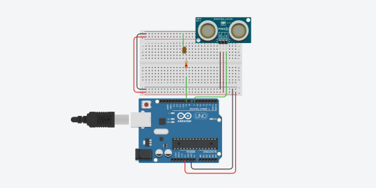
Ping Sensor
This experiment started with a ping sensor test that I did at home. I started by making an LED flash at the speed of the ping, and then evolved this so that an RGB LED’s red to blue value would change depending on the ping.
// establish variables for duration of the ping, and the distance result // in inches and centimeters: pinMode(pingPin, OUTPUT); long duration, inches, cm; // The PING))) is triggered by a HIGH pulse of 2 or more microseconds. // Give a short LOW pulse beforehand to ensure a clean HIGH pulse: digitalWrite(pingPin, LOW); delayMicroseconds(2); digitalWrite(pingPin, HIGH); delayMicroseconds(5); digitalWrite(pingPin, LOW); // The same pin is used to read the signal from the PING))): a HIGH pulse // whose duration is the time (in microseconds) from the sending of the ping // to the reception of its echo off of an object. pinMode(pingPin, INPUT); duration = pulseIn(pingPin, HIGH); // convert the time into a distance cm = microsecondsToCentimeters(duration); int blue = map(cm, 50, 0, 0, 255); int red = 255 - blue; set_rgb(red, 255, blue); delay(100);
vimeo
Stepper Motor and Buzzer
In class, we were then introduced to stepper motors, a type of DC motor that measures a full rotation by counting steps. The motor has a gear inside that is rotated by magnetic current passing through a series of ‘phases’, coils surrounding it. Due to the high voltage the motor requires, it is also attached to a transistor, which alters the charge to a safe level. After figuring out the stepper motor, I worked with a partner to attach a ping sensor to the top of the motor, meaning the ping sensor could rotate from 0 to 180 degrees. It looked like eyes so we gave him eyebrows and named him ’Pascal’.
To test this was working, we hooked up a buzzer to sound whenever the ping was under a certain level, so Pascal would scream when something got too close to him. It was very annoying to test, because we had no control over the volume or frequency of the buzzer, but it was functional by the end of the session. We then switched the buzzer for a more functional speaker and changed the tone of the sound depending on the ping distance, so Pascal could essentially use sonar to map a room.
int duration; pinMode(ping,OUTPUT); digitalWrite(ping, HIGH); delayMicroseconds(2); digitalWrite(ping, LOW); delayMicroseconds(5); pinMode(ping, INPUT); duration = pulseIn(ping, HIGH); Serial.println(duration); int freq = map(duration, 0, 12000, 1000, 0); tone(buzzer, freq); // step one revolution in one direction: myStepper.step(stepsPerRevolution); // step one revolution in the other direction: myStepper.step(-stepsPerRevolution);
vimeo
vimeo

Evaluation
This was another fun project, and it was good that Aaron and I could work on it together, as we could make a lot of progress. Though there were a few mishaps with understanding the tone library, and confusing a buzzer for a piezo, once again the combination of these components was very satisfying. I really enjoyed using the piezo once we got it working, and I think I would like to do something involving sound in my final artefact.
0 notes
Photo

AFCS Infographic
This is an infographic about how the Automatic Flight Control System, otherwise known as an ‘autopilot’, functions aboard a standard issue commercial plane, in this case a Boeing 747. Included is an explanation of ‘control modes’ and descriptions of the three main control surfaces: ailerons, elevators and the rudder. These are linked together with a diagram explaining how the autopilot obtains sensor data and compares it against the set control modes. If the autopilot detects a discrepancy, it issues a command to the control servos to adjust the appropriate control surface. The location of each are indicated on the plane.
References:
Harris, W (2007). How Autopilot Works. [online] HowStuffWorks.com. Available at: https://science.howstuffworks.com/transport/flight/modern/autopilot.htm [Accessed 20/03/20]
Modern Airliners, (N/A). Boeing 747 Specs. [online] Available at: https://modernairliners.com/boeing-747-jumbo/boeing-747-specs/ [Accessed 23/03/20]
Kostas Makris, (N/A). Accelerometer. [online] Available at: https://www.k-makris.gr/accelerometer/ [Accessed 22/03/20]
Lopez, D (2018). Horizontal Stabilizer - Elevator. [online] National Aeronautics and Space Administration. Available at: https://www.grc.nasa.gov/www/k-12/airplane/elv.html [Accessed 23/03/20]
SKYbrary, (2017). Elevator. [online] Available at: https://www.skybrary.aero/index.php/Elevator [Accessed 24/03/20]
SKYbrary, (2017). Ailerons. [online] Available at: https://www.skybrary.aero/index.php/Ailerons [Accessed 24/03/20]
SKYbrary, (2017). Rudder. [online] Available at: https://www.skybrary.aero/index.php/Rudder [Accessed 24/03/20]
0 notes
Text
Potentiometers and Servos
Potentiometer and RGB
The first thing I tried after hooking up the potentiometer was adjusting the red and blue values of an RGB diode. The potentiometer is another component that uses a potential divider circuit to read values, as the most accurate values come between resistance. You can see this circuit in the images below.
int input = A0; int b_pin = 11; int g_pin = 10; int r_pin = 9; void setup() { pinMode(input, INPUT); pinMode(r_pin, OUTPUT); pinMode(g_pin, OUTPUT); pinMode(b_pin, OUTPUT); } void loop() { int val = analogRead(input); int bVal = map(val, 0, 1020, 0, 255); int rVal = 255 - bVal; set_rgb(rVal, 255, bVal); }

vimeo
I then adjusted this code to also include a green value, so it traversed through the rainbow.
void loop() { int val = analogRead(input); int newVal = map(val, 0, 1020, 0, 150); if(newVal <= 50){ int led = map(newVal, 0, 50, 0, 255); set_rgb(led, 255, 255); } else if(newVal > 50 && newVal <= 100){ int led = map(newVal, 50, 100, 0, 255); set_rgb(255, led, 255); } else if(newVal > 100){ int led = map(newVal, 100, 150, 0, 255); set_rgb(255, 255, led); } }
vimeo
Servos and LDR
I also had time to work with a servo this lesson. The one I worked with used a 180 rotation scale, and I attached an LDR to it to create a light seeking mechanism. The servo will rotate from 0 to 180 until the LDR senses a light level above 170, then it will stop. It’s not perfect, but it works pretty well, and is a good start for combining complex elements together.
#include Servo servo; int input = A0; int pos = 0; int posMove = 1; void setup() { pinMode(input, INPUT); servo.attach(3); } void loop() { int val = analogRead(input); if(val < 170){ pos = pos + posMove; if (pos <= 0 || pos >= 180) { posMove = -posMove; } } delay(25); servo.write(pos); }

vimeo
Evaluation
I really enjoyed this session. The potentiometer really helped me understand how the potential divider works, and was good practice for reading inputs. The servo’s were very fun, and combining them with the LDR’s was enjoyable, showing how separate components can work together to create something new. I think LDR’s can be very useful in the future.
0 notes
Text
RGB Light Sensor
RGB Light Anode
For this session, I purchased some RGB LED’s to use as I wanted to experiment with them. The first experiment is learning how to manipulate each value and properly wire the circuit, as these nodes have 4 pins. I quickly discovered the LED’s I had bought were anodes, meaning they had to be connected to the voltage rather than the ground. This also means the high and low values are also swapped, so 255 is low and 0 is high.
void loop() { set_rgb(255, 255, 0); delay(1000); set_rgb(255, 0, 255); delay(1000); set_rgb(0, 255, 255); delay(1000); } //function to set the led each time void set_rgb(int r_val, int g_val, int b_val){ analogWrite(r_pin, r_val); analogWrite(g_pin, g_val); analogWrite(b_pin, b_val); }
vimeo


Light Sensor LDR
In this experiment, I used an LDR to measure light readings, and used those to adjust the brightness of an LED. The LDR utilises a circuit named ‘potential divider’ which takes a reading of voltage between two resistors, allowing for more accurate results. You can see this in the circuit diagram. As the light readings were a bit low (around 0-50) I used a map() function to scale them appropriately for the LED. I then adapted this to have two LDR’s, each of which would control the Red and Blue values of an RGB LED.
int analog1 = A1; int analog2 = A3; int b_pin = 11; int g_pin = 10; int r_pin = 9; void setup() { //SETUP PINS pinMode(analog1, INPUT); pinMode(analog2, INPUT); pinMode(r_pin, OUTPUT); pinMode(g_pin, OUTPUT); pinMode(b_pin, OUTPUT); } void loop() { //GET AND PRINT READINGS int value1 = analogRead(analog1); int value2 = analogRead(analog2); int newVal1 = map(value1, 0, 50, 0, 255); int newVal2 = map(value2, 0, 50, 0, 255); set_rgb(255, newVal1, newVal2); }
vimeo


Evaluation
The concept of the potential divider circuit was a little hard to wrap my head around, as I’m still struggling to understand how current and voltage works. However seeing how one component effects the other is very satisfying, and it was nice to have the opportunity to build on this.
0 notes
Text
First Light - 200220
This is my first time experimenting with Arduino, LED’s and any kind of physical computing. Today I built a blinking and fading light.

Blink
This is a simple script to make the light blink, and was the first experiment using the Arduino IDE and C. By default the scripting is split into a setup function and a loop function, and then any other functions that can be called in either. Below, the ‘led’ variable was used to specify the pin on the arduino. This script sets the led pin voltage to ‘HIGH’ (on), waits 1000 milliseconds (one second), then sets the voltage to ‘LOW’ (off) and waits another 1000 milliseconds. This then loops.
void setup() { pinMode(led, OUTPUT); } void loop() { digitalWrite(led, HIGH); delay(1000); digitalWrite(led, LOW); delay(1000); }
vimeo
Fade
The fade script follows a similar code. The variables ‘led’ and ‘brightness’ are set to a specified pin and 0 respectively. With each loop, the brightness is increased by the fade amount. This is set to a negative number if the brightness hits 255. ‘DigitalWrite’ is changed to ‘analogWrite’ as the program needs to write on a 1-100 scale rather than 0-1.
analogWrite(led, brightness); //has to be done with analog (1-100) // change the brightness for next time through the loop: brightness = brightness + fadeAmount; // reverse the direction of the fading at the ends of the fade: if (brightness <= 0 || brightness >= 255) { fadeAmount = -fadeAmount; }
vimeo

Evaluation
This is a good first start, and I really enjoy how easy it is to see the results with Arduino. There is definitely a lot of room for customisation with this kind of technology. Though I am not familiar with C, it seems easy to learn, and I’m exited to see what kind of cool stuff I can make.
0 notes