Statistics
We looked inside some of the posts by skrrrrrrttt and here's what we found interesting.
Average Info
Notes Per Post
373K
Likes Per Post
157K
Reblog Per Post
216K
Reply Per Post
3
Time Between Posts
3 months
Number of Posts By Type
Photo
10
Video
2
Text
4
Note
1
Last Seen Tumblr Blogs


Fun Fact
Tumblr’s reach among the 26-to-35-year-olds in the US is 11%.

Text
Homebrew Z80 - Mail time

Amazon order came in, and I think I’ve got everything I need to make something interesting happen. Here’s what I’m working with:


Components from Mouser:
6 MHz CMOS Z80 CPU
64K (8k x 8) Static RAM
2 MHz Crystal oscillator
A few types of 74HCXX series logic ICs
8 and 4 position DIP switch blocks
And some extra goods from Amazon to help with development:
3 Breadboards
2 Veroboards
A shitload of 3mm LEDs
I really cheaped out on the breadboards and LEDs, but I’m actually really impressed with the quality. The breadboards were “Elegoo” brand and only about $7.99 for a three pack. That’s less than the single breadboard cost me at Fry’s the other day. I was surprised to see that they came in some really high quality packaging, and the boards themselves were cleaner, whiter, and straighter than an altar boy. Hell, the American-made, $8 breadboard I just bought came in a plastic bag and looks like it’s made out of recycled milk jugs.


The LEDs came in white, blue, green, red, and yellow. The leads are sturdy, the lights are bright, and I’ve yet to have one fail. They even came in a convienient labeled box. I think I paid less than $15 for 750 of them. LEDs at Fry’s were something like 25 for $5.00, which is a total rip.


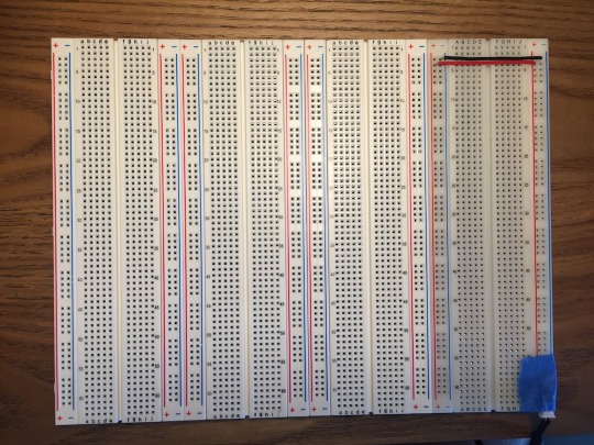
I had originally considered building the computer on a 160x100mm eurocard board, but I feared that would be much too small for a single-board computer after drawing it out on paper. I saw that Amazon had some larger Veroboard-branded stripboard available through Prime, and I thought that it might be better to try to use that first, then make some eurocard based multi-card computer system later. I’m glad I did, too. a 10”x5” piece of stripboard sounded massive after looking at 160x100mm eurocards all night, but I was surprised to see how small even 10”x5” looks in person. You can see the comparison in the picture below, with my small wireless mouse included for reference as well. There’s no way in hell I could fit everything on a single eurocard.


For now though, I’ll be building everything on breadboards while I design and experiment. I had no trouble attaching the new Elegoo breadboards to my other one. The four boards should give me plenty of room to work with while I’m getting started.
Now that I can fit more than just a clock circuit on the board, I should be able to plug in the Z80 and get to work.
0 notes
Text
Homebrew Z80 - Clock

My shipment from Mouser came in, and my desk is now covered in ICs, resistors, LEDs, and jumpers.
Ciarcia’s book and other sources online start the building process off with the clock, so I did the same. This was my first time working with ICs, and the clock seemed like a simple and rewarding place to start. Flashing LEDs will can make anyone feel like they’ve made something cool.
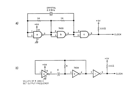
My first attempt at a functioning clock was Ciarcia’s single step design using a 7000, 7404, and an SPDT switch. This seemed simple enough, just like any circuit where a component is turned on with a switch. I also set up the slow clock, made with a 7404, capacitor, and resistor, as pictured in the book. A 4-pin DIP switch block selected between the two clock circuits.
I had trouble testing and getting any validation from these circuits though. I tried hooking an LED up to the circuit’s output and connecting the cathode to ground, but I think this resulted in the LED emitting all the time due to the clocks 330 Ohm pullup to 5V. At the time, I hadn’t realized how IC logic worked outside of putting a high or low voltage signal in on one side and recieving a high or low voltage signal out of the other side. It took a day or two to discover that an LED could reach ground through an ICs output when the output pin was in a low state. For now, I took the circuits apart, cleaned up, and called it a night.
The next day, I tried to make sense of the previous night’s errors. I tried to put together a logic probe circuit, but lacked some of the materials. I figured that my Arduino might be able to read logic high or low through the input pins, so I searched online to see if anyone had set up an Arduino as a probe. I found a few solutions that not only worked as a probe, but even as a full-blown multi-channel logic analyzer. Hell yeah! Setup was simple enough: upload the sketch to the Arduino, choose a port and baud rate, and launch the LogicSniffer software. The sketch implements a protocol fot interfacing with the open-source logic analyzer software. I set up a manual clock circuit as a I had the previous day, then started up the analyzer. I flipped the switch and captured data from the device a few times and was able to see the input switching between high and low. Seems like everything had actually been working, but I just couldn’t see it before due to wiring errors.
If you want to try the logic analyzer, you can find the Arduino sketch on Github here and the LogicSniffer software at the creator’s website here.
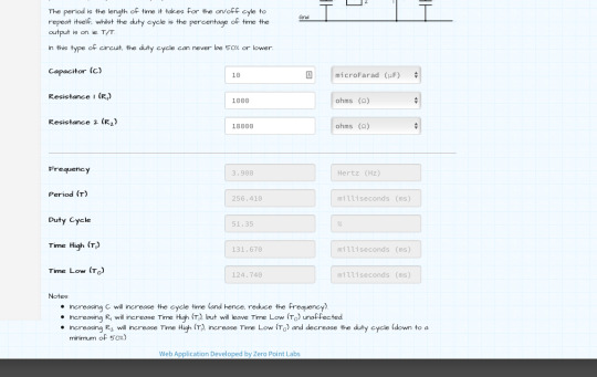
Feeling a little more confident and prepared, I watched Julian Ilett’s Z80 video again. He seemed to set everything up so quickly and easily, so I attempted to copy that. Julian used a simple 555 astable circuit to clock his Z80, and the 555’s output was even able to power an LED to show the clock’s pulse. I found a website for calculating 555 timer setups and figured out what I’d need to get a circuit that would flash around 4 times per second with almost a 50% duty cycle. I dug the components out of my drawers and got a similar set up and working. The first flashing LED; cool!
After getting the slow clock set up, I was anxious to get the blazing 2 MHz oscillator from Mouser up and running. The clock I bought was an all-in-one crystal oscillator circuit. All I had to do was hook up 5V and ground to have a perfect clock.

I ran both outputs through a 7404 before hooking up the LEDs so I could measure the real outputs, take some current off the ICs, and still have flashing light to match the clock pulses. The 555’s LED was looking great, but the oscillator’s LED stayed a dull green. That seemed like it might be correct though, due to the circuit toggling 2 million times per second.

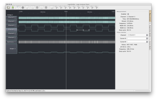
To be sure, I hooked both up to the Arduino’s digital pins and started up LogicSniffer. The captured data looked great! My 555’s wavelengths were uniform, and the oscillator was putting out a perfect 2 MHz square wave. I did notice that the 555’s frequency was a bit slower than the value from the calculator. Off by like 0.3 Hz even, which seems like a lot when the calculated frequency was only about 3.9 Hz to start with. Perhaps this is what the resistor tolerance is about. I’m using an 18k resistor in the 555, so if it’s 5-10% off, the actual frequency may be correct after all.
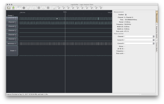
The analyzer started acting up after a few more captures, especially when I got the clock selector switch up in the mix. A consistant pattern started to emerge on any channels with a wire inserted, and I eventually noticed that the strange wave was at 60 Hz, which must be interference. No amount of unplugging and restarting could make the interference go away. I tried using decoupling capacitors and pullup resistors, but those didn’t make a difference either. When I disconnected my clocks from the Arduino, I saw that the interference was still there, so my clocks probably aren’t the issue. Even with the interference problem, I highly recommend LogicSniffer if you’re broke and clueless like me.

0 notes
Text
Homebrew Z80 - Power Up

I picked up a bigger breadboard at Fry's, along with a few logic chips to play around with while waiting for my shipment from Mouser to come in. When I got home and started setting things up, I realized that the only way to get 5V power to my breadboard was through jumpers from my Arduino's 5V and Gnd pins, which isn't going to work if this project is going anywhere. It was late and I was impatient, so I decided to improvise. I keep a giant bag of old phone chargers and USB cables stashed away just in case, and I rememebered that USB wall chargers put out 5V, even up to 2A sometimes. I said fuck it and got to work.
I recall from my XDA-Developers days how people used to praise BlackBerry USB cables for their thick conductors and reliablility. I needed to be able to solder or crimp onto the power lines of the USB cable to get some kind of connector working, so a BlackBerry cable seemed like the best choice. Upon snipping the micro USB tip off and slicing down the insulation, I was greeted with a mess of wire strand shards all over my desk, which will probably end up stuck in my feet later. It seems that the cable was shielded pretty well. The power conductors ended up being very, very thin, and mostly consisted of some synthetic fibers inside the insulation, perhaps for strain relief. I was already this far in, so I stripped back some wire, cut up a breadboard jumper, and attempted to splice the two together. It actually ended up working, but god what an ugly cable.

I could not imagine this new piece of crap being nearly as reliable as the original cable, so I tried to see what else I could find. I came across the wall adapter for an old active USB hub that I don't use anymore and was pleased to see that it put out 5V at a nice 3A max or so. The cables were super thick and there were no extra cables, or shielding to get in the way. I cut the plug off the end and was presented with two nice, strong, shiny copper wires. The wires ended up being too big to stick into a breadboard, so I got some heatshrink and snapped off two header pins and soldered it all together. This one ended up looking much better, but I did have trouble keeping in the breadboard. I also didn't like having those two conductors right next to each other, soldered onto the header pins. I could see that shorting out at some point.

Anyway, fucking up those cables took long enough to where I didn't get to mess with any of my new ICs that night, and so I just drove to Fry's in the morning to find something better. Most of the universal, adjustable DC adapters were at least $20, which I wasn't looking to pay right now. In the prototyping section, I did come across something like my hacked-together USB cable thing, but done correctly. This cable has a male USB A connector on one end, and a DC barrel jack on the other. Nice! I think this cable was about $3.00.

I still needed a female connector to get the power to the board though. I couldn't find any jacks that would fit on a PCB, but in that same prototyping section, they had a female DC jack with a two pin "JST" connector on the end, like you might see on a computer fan or sensor cable. I couldn't find any female JST connectors in the store, but I thought I could maybe fit two right-angle header pins in there and stick that in the breadboard.

This ended up working very well. The connection is loose, but that's nothing some tape can't fix for now. I finally have some reliable power from the wall. Total cost of power stuff was about $6.00 I think. I now see that I could have gotten a 5V wall charger and a proper connector online for less than $5, but instant gratification is a bitch, and I lose all patience as soon as I get really excited about a project.

I think this should do the job while I'm prototyping on the breadboard, and I'll be ordering a proper barrel jack to solder in when I move to PCB. If the USB cable in the phone charger isn't providing enough current when the project is further along, I'll get a male tip for the USB hub charger to get that sweet 3A.
0 notes
Text
Homebrew Z80 Project - Intro

I make software. I like my job very much. I get paid to sit at home and code all day, which is exactly what I would be doing if I didn’t have a job.
Hardware is just cooler though. Hardware hacks will always be cooler. Nothing beats the feeling of making something you can see with your eyes and use with your hands. It’s been a while since I’ve been able to take on a project where I get to try something completely new. I don’t really know anything about the hardware behind computers, so I’m going to make one. This project will be serving as an exploratory experience of sorts; I’ll try to keep to reading data sheets and probing around with meters instead of following any guides and tutorials too closely. I will surely be making a lot of mistakes along the way, so I wouldn’t recommend copying my steps too closely either, but feel free to follow along.
Why Z80?
No good reason. I didn’t know enough to choose from an engineering standpoint, but some quick googling showed that I’ve unknowingly been interacting with Z80s my entire life through calculators, video games, and embedded systems everywhere. I like that. They’re still used today, 40 years later. The name is cool. Good enough for me.
Project Goals
I plan to let this project be a learning experience and nothing more, but we’ll see how that plays out. Hooking up a keyboard, tape drive, monitor, and modem would be very, very cool, but I’ll be thrilled if I can get a computer I built myself to turn on and listen to a few instructions that I toggle in with switches.
I have seen a few homebrew builds with backplanes, custom bus patterns, and card-based hardware, and I like that very much. I think that my Z80 build will end up organized like that inside a nice enclosure eventually, but I think that would be biting off more than I can chew at the moment. I’ll be starting the project off as a single board computer. Getting the componenents to play nice together without worrying about bus and power issues will enough of a challenge for now.
I’d like to keep everything in the build simple and handmade. I’ll be using some newer test equipment while learning and debugging, but hopefully the end product will consist solely of hardware that would have been available in the 70s and 80s. I’m going to avoid buying any pre-fabricated boards or controllers, since that would really just be buying a slow, outdated computer for too much money. I’m also broke as shit.
I want the computer to have a name, too. I’ll be working on that.
Resources
I’ve been reading through Steve Ciarcia’s Build Your Own Z80 Computer repeatedly for the past week, and it’s been a godsend. Ciarcia explains why as much as he explains how, so I don’t think I’ll have too much trouble adapting his plans into my own designs. Donn Stewart’s CPUVille website has also been a source of inspiration. His schematics are simple and self-explanatory, and his expansion boards were all functioning prototypes on perfboard at some point, which shows that you don’t need printed circuits to make something functional. He’s even put out a guide for getting the Palo Alto Tiny BASIC from Dr. Dobb’s working on the Z80. One of the most motivating resources I’ve found is this video of Julian Ilett hooking up a minimal Z80 setup in a matter of minutes. No RAM, no ROM, and a 555 circuit as a clock. Shows that it’s possible to isolate components and take things one step at a time.
Components
I spent a night or two scanning all of the schematics in BYO Z80 and getting an idea of the parts I’ll be needing to get a basic setup running. I ordered a 6MHz CMOS Z80, 64k RAM, and a bunch of 74HC series ICs from Mouser. In my excitement, I also drove to Fry’s the next day to pick up a few extra chips to play around with while waiting on the shipment, as well as a bigger breadboard and some solid wire. I’ve never worked with ICs before, so having some extras around can’t hurt.
Since I don’t really know what I’m doing yet, I decided to wait to order a board until I knew I could fit everything on it. S100 prototype boards seem pretty expensive and hard to come by, and I’m not sure if a single 160x100mm eurocard will be big enough. For the next few weeks, I’ll be testing each module out on a breadboard and moving them onto something more permanent once I know everything will work.
0 notes
Note
How much strawberrys do I have to eat before my cum is flavorful??
The way your cum tastes is the least of your concerns. You should enroll in some GED classes.
104 notes
·
View notes
Photo

Hey tumblr, welcome to Georgia! Where my Miata can fit under your truck.
1K notes
·
View notes
Photo


Some more pop-up love <3 by: www.sexxx-on-wheels.tumblr.com
3K notes
·
View notes