
sonyacsmakerspaceblog-blog
Sonya's iDesign Blog
21 posts
Don't wanna be here? Send us removal request.
Last Seen Blogs

specialittleguy-blog
Roleplay

buffaloskyecat
Buffalo Skye Cat

workmanmathiassen29
The Blogging of Raymond 944

notyourfunnyman
WAYNE

enterolympus
Enter Mount Olympus and Tell Us What You Seek
Text
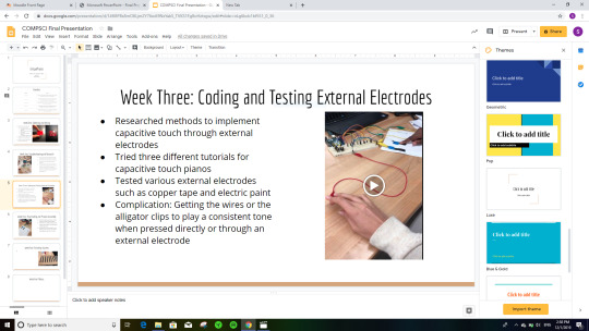
Final Project Week Four: Final Coding and Starting Product Assembly
Given the fact that I’ve been off campus for five out of seven days of the week, I think I was decently productive with my project this week. On Monday, I started creating my final product. I got a large cut of cardboard, measured out eight different keys, and painted the keys with black electric paint. I also was able to finalize my Arduino code, which then made each of the eight piano tones a note in the C major scale. I also decided to hook up one tone to two different external electrodes and it eventually worked. Leaving lab, I felt like I had made a lot of progress. Here is a picture of the piano I began to paint in lab:

Also, here’s a video of the electrode “keys” working as a touch input for the tone:
With that being said, I know that there is still a lot of work I need to do in order to finish my project. First and foremost, I need to hook up the other seven keys by soldering hookup wires on the bottom of the cardboard piano table. Then, I need to laser cut a box to hide the wiring I’ve used for the piano. If I have any extra time, I would also like to do a survey where people try out my piano with someone they don’t know too well. I would want to see if after a session of creating music together people would feel more empathetic to each other, but considering the fact that Monday classes has now been cancelled, I don’t think that I’ll have the time to do that unfortunately.
Anyways, I was decently productive this week. Even over break, I formatted and basically finished my PowerPoint presentation. Here’s a screenshot of the rough draft presentation:
0 notes
Text
Here’s a video of my friend and I making sick beats with the semi-functional capacitive touch piano I coded.
0 notes
Text
Final Project Week Three: Eventual Success
Finally my capacitive touch piano works. It was a painful process to get there, but we made it work before the end of the week.
During lab Monday, I attempted to follow the Arduino-based tutorial for the capacitive touch piano. After fiddling around with the code for a solid hour, not being able to figure out exactly why the “CapacitiveSensor” elements were not registering as they were in the example code. Eventually, I realized that I needed to download the actual “CapacitiveSensor” Library via Arduino and that made all the difference… or so I thought. Shortly after my false success, I ran into an issue where the Arduino processor was not picking up the “c.s2_10″ element. I eventually realized that there must have been an internal issue with the code or the CapacitiveSensor library after doing some diagnostic work with Professor Snyder. Even though I wired the circuit board perfectly (based off the diagram I found in the tutorial I mentioned in last week’s blog post), the code was simply not translating over to the board due to this tone being undefined in the code.
Additionally, I was trying to implement the capacitive touch sensors I ordered into my project, but that too seemed like a futile effort. On both Monday and Wednesday, Professor Snyder and I spent a collective two hours looking at my Arduino code, and my capacitive touch sensor circuitry in relation to the piano circuitry. Despite our efforts, we couldn’t pinpoint what element was causing the issue of the serial monitor not picking up the inputs from the touch pad. However, when we tested the touch pad on its own separate breadboard with the setup code directly from the touch pad manufacturer, we realized that Arduino was still not reading the touch pad inputs. The touch pad merely lit up the touch pad’s internal LEDs which led me to believe that the touch pad was either: a) not coded correctly to read + print the inputs from the touch pad (this is likely), or b) perhaps the touch pad was not created with the function to read and translate specific touch input information to the serial monitor.
Anyways, I left Wednesday’s class section feeling defeated. I really thought one of the tutorials I found last week would work out. But at this point, I realized that not only would I have to create an external electrode for my project, but I would also have to find a whole separate tutorial where the code wasn’t corrupt. I went into the Makerspace Friday morning with the intention of working on my code and the second tutorial I found with Angela, but she unfortunately was not at the Makerspace at the time I thought she was doing TA hours, so I just worked on a different assignment.
Flash forward to today, I was able to find a different Youtube channel for a capacitive touch piano this morning. It looked simple enough and promising, so I decided to go in this afternoon and try to figure out this capacitive touch piano one more time. I went in not confident in my ability to figure out the code or the project by myself, but ultimately I put my worries aside and just started with baby steps. I tested some electric paint to see if any electricity would be sensed through it. Success. I then followed the Youtube tutorial and associated blog post for the wiring of the Piezo speaker and the board. Success. I then implemented the code (which had no errors) effortlessly. Now was the moment of truth: putting all the elements together to test the product. I sheepishly taped the wire to the electric paint and pressed lightly on the paint “key”. Nothing. I pushed a little bit harder and a little bit longer… and a small hum of sound came out of the finicky Piezo speaker. Success… kind of?
After tinkering with the code as well as my circuitry, I discovered that the line of connection between all the resistors was somehow not strong enough. A simple cable was able to fix that issue and then the piano worked! I was also able to hook up a couple more speakers to my breadboard so the piano emitted a louder buzz with the touch of the key. Although there are a few minor kinks to work out, I was able to troubleshoot and work out all the issues I was facing for the past couple of weeks! This success puts me back on schedule to work on a few final touches or testing other potential elements such as LEDs for the final couple of weeks. I’m very happy with the result of today’s session in the Makerspace. It feels like a very big step for me as the designer considering the fact that up to this point I would hesitate to work on my projects without assistance from Angela, Professor Snyder, or the Fimbel lab workers. Today I was able to prove to myself that I am competent in my own right when it comes to troubleshooting circuitry/coding errors. Through solving this major issue without the assistance of the people mentioned above, I realized that I’m able to be successful on my projects independently as long as I approach the project with diligence and patience. I’m very proud of myself for pulling through and being able to make this capacitive touch piano prototype work after many struggles.
Here’s one video of my capacitive touch piano working (I’ll post a seperate in a different blog post since I can only include one video per blog entry):
Also, here’s a link to the tutorial that WORKED to my delight :)
https://www.youtube.com/watch?v=sqQzIN7G6Oc
and here’s the blog associated with the tutorial:
https://mrelectrouino.blogspot.com/2019/08/arduino-piano-diy-conductive-paint.html
0 notes
Text
Final Project Week Two: Troubleshooting and Research
So let me start by saying that this week was NOT productive. I was unable to get done what I wanted to get done which puts me behind schedule at this point. In lab, I wanted to set up the touch element to play a specific note. But then shortly after attempts to play music off the Arduino and Redboard, I quickly discovered that neither board actually has a built in speaker. I thought it was standard for every board to have a built-in speaker but apparently I was mistaken. That meant that I had to dig through the electronics cabinet at the Makerspace to find a couple of Piezo speakers. Setting up those speakers was a pain because the wiring diagrams online were very confusing. Even when I figured out the correct setup, I was drastically underwhelmed by the quiet buzzing sound the finicky speakers made. I unfortunately was not able tot get a video of the speakers working and I’ve since changed the wiring and the code so unfortunately I do not have any video of the project I can post.
From that point forward, I once again tried to do a setup of the speaker audio to react to the capative touch by combining the code. But even then, the two elements were going off at separate times and not connected to each other in the code. That’s when I realized that this project was going to be much more complicated than I anticipated. In the process of figuring out how to code the two elements together, I came across a few resources that are step-by-step guides for how to make capacitive touch sensor pianos. Then, that was the end of my lab: I didn’t get anywhere new, I just encountered a lot of problems with my project unfortunately.
After lab I wanted to meet with Angela and figure out what my next steps would be. I tried to email her but I think this time of the semester is busy for everyone, so we were not able to find a time to meet. The past couple of weeks I’ve had very big projects due in my other classes, so I haven’t had the space to focus on this project, but this week I really want to dig in and focus on this project. I’m just going to start from square one in lab next Monday and try to follow one of the capacitive touch piano tutorials.
Here is a link to all the resources I found in lab last Monday if you’re curious!
Capacitive Touch Piano Tutorials:
https://www.instructables.com/id/Capacitive-Touch-Arduino-Keyboard-Piano/
Or
https://create.arduino.cc/projecthub/San_Ismail/paper-piano-with-arduino-e27da7
Capacitive Touch Keyboard Library Link:
https://github.com/PaulStoffregen/CapacitiveSensor
Redboard Music Guide:
https://cdn.sparkfun.com/datasheets/Kits/SFE-SIK-RedBoard-Guide-Version3.0-Online.pdf
0 notes
Text
Final Project Week One: Soldering and Wiring


Last Monday when I was at lab, I received all the parts I ordered from Sparkfun and I decided a good first step would be to get one of the touch pad sensors working. In order to do this, I referenced one of the touch pad setup articles I found earlier in my parts ordering process. I was able to read through the article beforehand so I had a vague idea of what I was doing. However, what I didn’t realize before is that in order to setup the touch pad sensor to go off with the breadboard + Redboard combo, I needed to solder on male PTH headers onto all eight of my touch pads. Having never soldered before, I looked up a separate video explaining how to solder and then I practiced the technique on old SquareWears for about an hour until I got the technique down. From that point forward, I got my male PTH headers into the touch pad. Using alligator helper hands (which were really hard to set up) I eventually got the touch pad balanced on the headers and proceeded to meticulously solder the headers to the touch pad. From that point forward, I let the touch pad cool down and then I got out my all too familiar breadboard and wires. Going off some of the Sparkfun setup diagrams, I was able to figure out the wiring necessary to connect the touch pad to the breadboard and then the Redboard. From that point forward, Redboard had Arduino-based code I could use to set up my red board so I easily uploaded it to my Redboard and I was able to get my board working 10 minutes after lab technically ended. Here’s a video of the touch pad working. The light on the pad lights up green when it’s activated.
From this point forward, I’m most likely going to explore coding a tone for the touch pad sensor for my proof of concept prototype next lab session. Once I figure out the code and tone + LED light up for one touch pad, I will solder male PTH headers onto my other 7 touchpads and explore the wiring necessary for the touch pads to get to the Red Board + the coding needed for each touch pad to play a different tone.
0 notes
Text
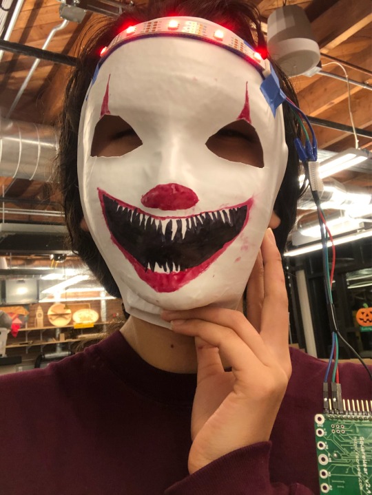
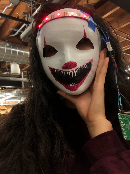
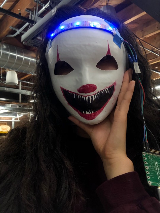
Lab 7: Masks (Light Up the Fright)
So my project is a Pennywise mask that has a light up dot star strip on the forehead. The steps of this project were to: 1. Use the vacuum former to create a face mask mold, 2. Download and edit the code to fit the dot stars I grabbed, 3. Cut out the mask from the mold using scissors and cut out the eye slots using an Exacto knife, 4. Design the mask using markers and an image of Pennywise, and 4. to connect the wires and the dotstar LEDs to the mask using masking tape. I am proud of how even and clean I was eventually able to make the eyes since the material is a little difficult to cut through with an Exacto knife. I wish I could think of a more creative way to add the lights, but I still think the lights look good where they are. If I had the time, I would have also liked to figure out how to attach ears to the model so I could have made a Panda mask. Overall, I’m happy with the project and I’m glad it’s done just in time for Halloween!! :)

0 notes
Text
Lab 6: Eye Design Part 2
For the final project of this week, I decided to make a music box that plays “Redbone” by Childish Gambino when you open the lid. After Lab 6 Monday October 21st, I decided that I was going to get laser cutter training last Wednesday. I went in and learned the basics of Adobe Illustrator, and then I booked the laser cutter again Tuesday the 29th so I could create my box. I created this schematic after Lab 6 depicting the design I wanted to go for:

As for the coding of the SquareWear, during lab this Monday (Oct. 28th) I spent nearly the entire time trying to figure out the code needed for the SquareWear to play music upon opening the lid of my box. Angela was there to help me through a lot of the issues I was having, yet we were still having issues triggering the “If... else...” statement on my code since Arduino wasn’t recognizing the two statements as connected to one another. Another issue was the fact that my code wasn’t recognizing my “playPerformance” line as an action the SquareWear needed to complete when the light sensor reaches its threshold. I first tried to code in the performance as “voidplayPerformance ()” before voidLoop as professor Snyder suggested, but for some reason my code wasn’t calling on the “playPerformance” definition after the light threshold was reached (it was defined but not triggered which meant the song was not playing at all). Then, Angela and I moved playPerformance into the directions of void loop, but then the SquareWear would just loop the song instead of having it triggered by a threshold reached in the light sensor. After about an hour and a half of Angela and I fiddling with the code, professor Snyder was able to fix the code so that the light sensor reaching its threshold triggered the music. Here’s a video of the code for my SquareWear (finally) working properly:
From that point forward, I went in the following Tuesday, I had a little bit of a hard time with the laser cutter. I had a couple of the Fimbel Lab Workers help me and they didn’t have any plywood, so I switched my material to a hardwood-like material which they also only had a little bit of. The first time I lined up the laser cutter with the help of the worker, everything went according to plan. We had to cut the box pieces on two different pieces of hardwood material which complicated things further since one of the hardwood pieces was very thick and not cutting through the hardwood until its third time under the laser cutter. The laser cutter was misaligned the second time I tried to cut the pieces which meant that I had to flip my box material outwards hence the reason for the gritty outside versus the smooth finish. I ended up liking the design the laser cutter engraved in the box so I stuck with it and glued the box front with the smooth side facing outwards. Additionally, the lid has the unique engraving which I think was a happy accident.
Here are some pictures of my final product:


I definitely had a few mishaps in this project between the coding and the laser cutter, but overall I think the project turned out really nice and I’m quite proud of this music box I made. If I had more time, I would have liked to make a box where the lid hinges open and maybe I would have liked to decorate the box more.
0 notes
Text
Lab 6: Eye Design Part One
Abby and I decided to work together to make our SquareWear creatures communicate with each other. My SquareWear creature was named Yuki and Abby’s creature was named Cheryl. We both modified the lab code we received to make sure Yuki and Cheryl were communicating with each other. The steps of this process were to create a light sensitive “speaker” that flashed with bright white LEDs (Yuki) and then Cheryl was the “listener” that used its light receptor to detect Yuki’s bright white flashing light to then glow a red LED and communicate accordingly. For your reference, here’s a video below demonstrating that process:
To answer the forum questions:
Blog Question 1.1:
Partner A's light sensor value: ____800__ (on) __50_____ (off)Partner B's light sensor value: ____750__ (on) ___100____ (off)
Blog Question 2.1: What does the above code do? If you're not sure where to place the code, discuss with your partner where are your options?
The above code is able to distinguish when the threshold is reached and tell the program to turn on the white light.
Blog Question 2.2: Where should you put this code? Within which method? Between which lines?
The first “if” statement should be placed below the Serial.println statement and above the code used to turn on the new red light. Then, the “else” statement should be placed below the closed bracket of the red light on code and above the code needed to turn the white lights off.
Blog Question 2.3: What happens when you the two "reflector" SquareWears interact? Does one light up? Does both light up? Neither?
Neither of the lights would light up since they are both in reflector mode and the brightness of the room would not reach threshold and have an effect.
Blog Question 2.4: What will happen if your modify the programs so that the white light turns on when the SquareWear detects that it is in the dark? Does one light up? Does both light up? Neither?
The SquareWear won’t interact with each other, but if the SquareWear reaches a threshold less than 100, then the red light will turn on.
Blog Question 3.1: In the loop method, what does the "speaker mode" code do? Describe what you expect the square wear to look like while it is in "speaker mode."
The speaker mode code continuously turns on the white blinking lights to “speak” to the listening code. In the speaker code, the SquareWear should have white flashing lights.
Blog Question 3.2: In the loop method, what does the "listener mode" code do? Describe what you expect the square wear to look like while it is in "listener mode."
The listener will have a red light which shows it is recording what the speaker is saying.
Blog Question 3.3: Cover the light sensor with your finger. What do you observe?
No matter what, the white light will turn on but the red light will not since it cannot record/ react to outer light when the sensor is blocked.
Blog Question 3.4: Hold the light sensor under a bright light. What do you observe?
The red light turns on and stays on because the light is higher than the threshold.
Blog Question 3.5: Now see if you can facilitate communication between the two square wears. Can both call? Do both respond?
You may need to adjust the threshold values in order to trigger the response. Both can call, but only one can respond at a time. (Reference video above)
Blog Question 5.1: Try changing the frequency of the buzzer. How does changing the frequency make the pitch sound higher or lower? Try a few values.
As the frequency of the buzzer goes higher, the pitch will also go higher and vice versa.
Blog Question 5.2: Sounds add another dimension to your creature. In a few sentences, discuss how you could add personality and individuality to your creature with light and sound.
So I’m planning to potentially make a music box you can activate with either 1) opening the box will turn on the flashing LED within the SquareWear and play one melody 2) speaking into the speaker will play a second song.
After our group project was complete, Abby and I decided it would be more conducive for us to do separate projects focused on music boxes that are able to play a melody based on the amount of light the receptors pick up. Once I’m complete with that project, I’ll create a second blog post for creating that project with the two clear pictures f the finished project, the code associated with it, and the features I found new, difficult, etc. I’ll leave you with a picture of “Cheryl” recording the light from my flashlight:
0 notes
Text
Elevator Pitch Lab
My elevator pitch is to create an Empathy Training Musicking Machine that combines the disciplines of music, technology, and psychology/neuroscience. Research in the field of psychology has suggested that shared music listening habits and collaborative music making deepens one’s empathy for others. With that being said, many people may be unable to sing or play an instrument, so collaborative music making technology would be able to solve that gap. The potential market audience or demographic of my product would be any workplace looking for an innovative way to promote team building activities, or any classroom setting which could use collaborative music making technology to build empathy between people from various socioeconomic backgrounds.
My product would use SquareWear technology and multiple touch pads sensors to create a dynamic, interactive instrument where multiple people could help decide the tones and note values which go into a piece of musical composition. Depending on where someone touches the touch pad/ the amount of pressure they apply on the touch pad, different LEDs will light up to inform each participant what pitch or note value they are programming into the SquareWear. Once the piece is done, the instrument should be able to play back the music each person created. To learn more about my pitch here are some resources to check out:
My elevator pitch presentation: https://docs.google.com/presentation/d/1y4FReBMojRo7ZX7qlMbk3w4JCkBIbzpGk10b_oBO9lM/edit?usp=sharing
More Music, More Empathy Article: https://www.psychologytoday.com/us/blog/live-in-concert/201508/more-music-more-empathy
My 90 sec Elevator Pitch (Google Document): https://docs.google.com/document/d/1x725ymjVDMk-UWKfY9ObiEwiqh6HIQL4XAq2PTMgsS4/edit?usp=sharing
0 notes
Text
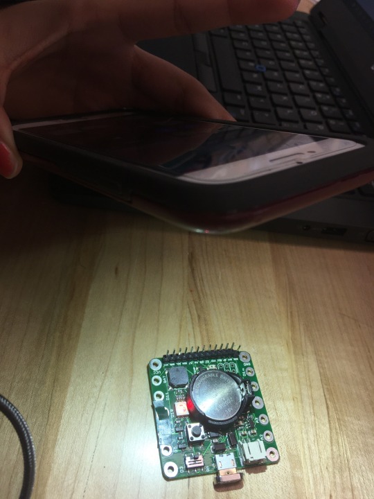
Lab 5: Input Via Microphone with SquareWear
So I’ve yet to finish my project, but at the end of lab the Monday before last, I felt like I made great progress on completing my project. I was able to implement the microphone into my SquareWear and correspond the various LEDs to levels of noise the microphone picks up. Here’s where my project was at the end of lab:
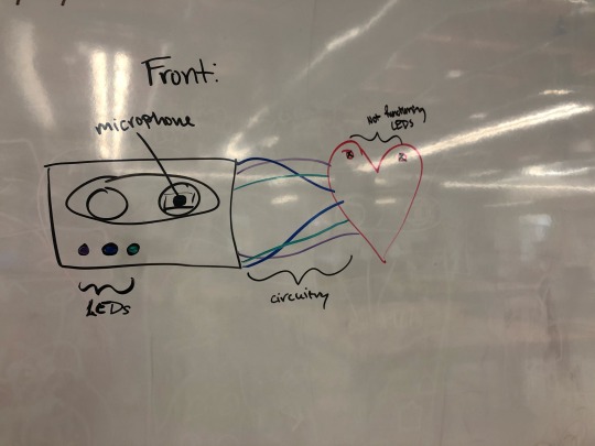
ORIGINAL PROJECT BRAINSTORM: I imagined my project to originally be a sort of heart connected to a green stem where the LEDs and the microphone could be sewn into the stem. As the noise gets louder, the LEDs closer to the heart would light up. I was going to use conductive thread to sew in each of my LEDs so that I would not need to keep the wires in my design.
CHALLENGES: However, there were various challenges I ran into while completing this project. For one, I had significantly less time to complete this project than I would usually have due to Fall Break. I was visiting home from Friday morning until Tuesday evening which made my time limited from the start. Because of other midterms I had last week, I put this project on the backburner and now I’m facing the consequences. In the future, I want to try and budget more time to work on my iDesign projects so I don’t find myself in this situation come Wednesday morning of the project’s due date. Additionally, when I came in Wednesday morning (today before the project is due), I found that none of the Makerspace staff is in office since they are all at a conference for the entire day. Without access to the Makerspace computers, I am unable to change my Arduino code which means that I had to improvise with my project:
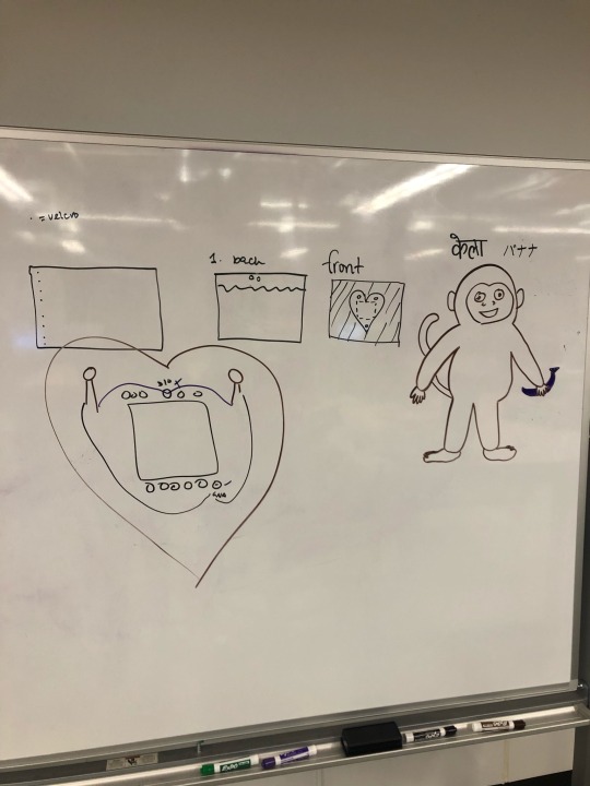
NEW PROJECT BRAINSTORM: Due to the fact that I am unable to change the code and there are no Fimbel lab staff members present I had to compromise my vision: I am going to keep the wires and my current setup as is, but I’m going to now make a project with the applicable software. My new idea is to sew a fabric pouch/ draw a paper pouch around the circuit board in the design of a mix tape and stick the microphone on that fabric patch and add it to the mix tape design. Then, I am going to leave it attached to my heart to show how much I love music. My goals of this new product were to:
1) keep wires visible in a design which would make sense with the exposed wires.
2) draw on past assignments/projects to complete this new design.
3) implement the microphone into my new design in a way that wouldn’t be awkward
4) Use the code that’s currently programmed in my SquareWear (and unable to be changed) to make sense in my design.
Here’s a schematic of my design:
After writing out the schematic, I used my business card from project 1 as a reference for my mixtape design. I cut a piece of paper that was roughly the same size, I marked where my LEDs and microphone would come through, and I got to work cutting, drawing, and decorating. Here is my final project:

If I were to do the project again, I would try to budget more time to fully complete the project. I would also make sure I understand the Fimbel lab hours and know in advance when the staff are going to be out of office so I can plan accordingly. As for my actual design, I think it’s pretty good based on the limited time and resources I had at my disposal. But my original project didn’t make a ton of sense with the assignment so I probably would have taken the time to think of another way to implement the microphone and LEDs into a project that makes more sense like a microphone and a guitar, a wearable, etc. rather than a heart on a flower stem.
0 notes
Text
This is a video of my patch fully working! Here’s my Lab 3 and Lab 4 video (๑>◡<๑)!!
0 notes
Text
Lab 3 Square Wearable and Lab 4 Light and Sound

Finished LEDs on heart patch
So I decided to actually create a combined project for lab 3 and lab 4 which uses the Squareware technology. In order to do this, I decided to make a wearable patch for my leather jacket with an attached felt heart that flashes its own unique LEDs (Lab 3), and it sings to the melody of Bohemian Rhapsody while the lights flash in the back (Lab 4).
Last week, during the Lab 3 hour, I learned about Squareware and how to correctly code the blinking lights. We used a very basic model called Blink where we learned the timing of the Squareware and how to program the lights to flash at certain times. It was my first time ever coding last week, so it was a little bit difficult to initially make sure all the brackets, parentheses, and void setup bits were remaining in the code. Additionally, not being able to save my code within Arduino made things more difficult when I had to copy and paste my code to and from my Google Doc every time I wanted to alter the code.
During lab 4 hour on Monday, I learned how to code the pitches and how to input quarter notes and the correct delays. The difficult part with this week’s coding was figuring out what parts of the code go where as well as, distinguishing which tone goes to which code. For example, I wanted my Squareware to play a Bb note, but there were 6 different octaves for Bb available so mapping out which octave of Bb I was specifically looking for was difficult.
My three goals for this project (lab 3 and Lab 4) were to 1. create a wearable that can also be functional 2. create a wearable I can use for this week and next week that has multiple functions and 3. create a wearable where the Squareware could be accessible for future alterations. With the help of Angela and many Fimbel lab student workers, I was able to create this really awesome heart pocket and I’m very very proud of it :)
Heart Project Flashing Light Schematic feat. Curious George

Finished Back of Heart (end of Lab 4)


Coding for Lab 3 and Lab 4
Flashing Lights (end of Lab 3)
1 note
·
View note
Text
Discussion 3: Why Wearable Technology Will NOT Replace Traditional Purchasing Norms
Although wearable tech is taking the fashion and technology industry by storm, I don’t believe that Wearable technology will completely replace the “traditional” way we sell products and here’s why:
I define “traditional” marketing/purchasing methods as buying clothes and products in person at a physical store front. While online shopping has admittedly increased within the last decade, there are still issues of not knowing exactly how a product might fit if you’re buying it online. There can sometimes be a huge difference in the quality of clothes you think your buying online versus the quality of clothes you actually receive. Popular online stores like Wish and Romwe are notorious for selling poor-quality, fast fashion items that sell due to their low price tag and misleading product photos. Similarly, wearable technology has yet to make an impact on the average consumer, which means that people who buy wearables could be weary of the items they receive in the mail.
Another reason online shopping is still on the backburner for some items is due to the fact that many people like to go to the mall to hang out and look at/ try on clothes before buying them. Malls serve as a gathering place for people from all different age groups and socioeconomic backgrounds to come together and partake in consumerism. To this end, going to the mall could be seen as a social activity to get one out of the house and into society, which could never be the case for online shopping.
If wearable technology were to come into the mainstream, then it would have to become commoditized by companies that could cheaply design wearable tech and sell it in stores for people earning average salaries. In the video, “Money No Object”, a woman named Heidi Hinder describes the recent work she has been doing in the field of technology economics. She specifically was exploring how to create a pin that would allow people to transfer money to the cashier at a store digitally. She was aiming to create a pin which redefined the way we pay for our products. Although this idea for exchanging currency is quite unique, it clearly still acknowledges the fact that in-person stores are still prevalent in today’s society. This video attests to the fact that wearable technology will still adhere to the traditional buying practices we have in place, not the other way around.
0 notes
Text
Lab 2: Soft Circuit Planning
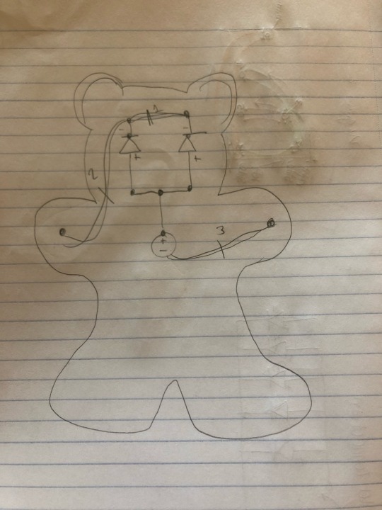
Finished Wiring Diagram pictured above
Creating a wiring diagram: I decided to first create a baby teddy bear. I chose blue LEDs for the eyes and they will go typically where eyes for any teddy bear would go. The battery will be placed towards the middle (or the heart) of the teddy bear to make wiring a little bit easier. The conductive thread for the positive side will be connected to each other and then connected to the positive end of the battery. The negative side will also be connected to each other by stitching the thread around the front to to the other negative LED end (to prevent a short circuit from positive and negative wires touching), then one negative LED will be connected to the left hand on diagram (refer to diagram above), and the other one hand will be connected to the negative end of the battery, so when the two sides clasp together the blue LED lights should light up. Then, everything was sewn up and stuffed!
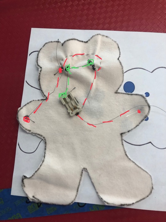
Just for your reference, here’s a picture of the marked fabric pieces before seeing my final circuit. KEY: red=negative wire connections, green=positive wire connections.
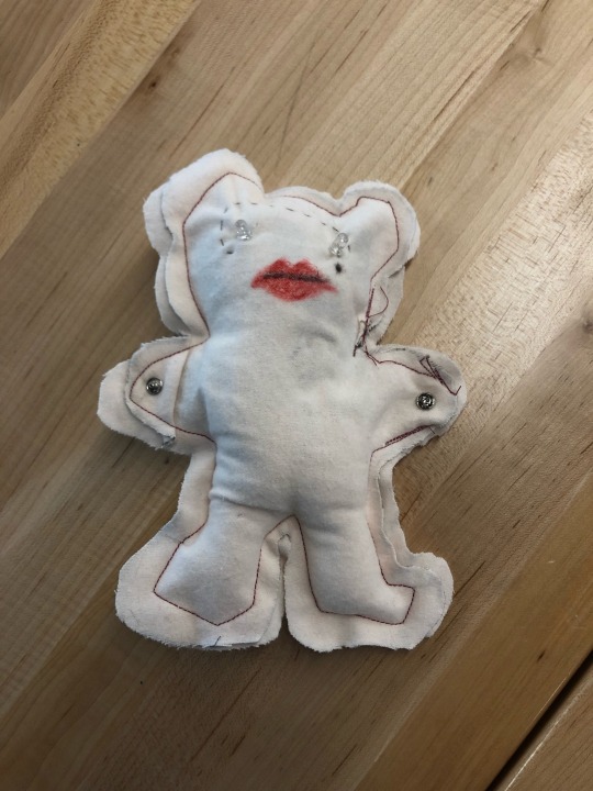
And here is a picture of the finished schematic:

After I completed the circuitry, Angela taught me how to sew and stuff the bear and then I completed my project! Here is a picture of my finished project:

0 notes
Text
What is Wearable Technology?
1. Wearable tech, from what I understand, is a new field of technology focused on bringing technology to the fashion industry in order to make our clothes more functional. Wearable technology can improve many fields including health and fitness, communication and fashion among other things. To be honest, I personally haven’t noticed a ton of applications to wearable tech in society, but there are devices like apple watches, fitbits, and heart monitors that are used commonly for health and fitness. In the 2000s, I grew up listening to music on my iPod shuffle. In a way, this simple music device that clips to your clothes could be referred to as wearable tech that allows people to exercise without having to hold a bulky device. Nearly 20 years later, we’ve come really far in our understanding of technology, yet we’re just scratching the surface of what is possible with wearable technology. Another prominent example I can think of from more recent years are the Google glasses available for people to buy, but I don’t think our culture has caught onto the idea of using these spy-like glasses in everyday life. I’ve never met anyone who owns a pair of Google or Snapchat glasses just because many people don’t see the point in spending money on tech you can access for free on your phone. With that being said, if wearable tech can become more accessible to people from various socioeconomic backgrounds, then it may gain popularity within the next few decades.
2. What surprised me with the video and the article was how much more prevalent and accessible wearable tech is compared to what I originally thought. Now that I think about it, there are many products that can subtly enhance awareness and communication like a Blutooth earpiece/headband. Many people are sewing LEDs into clothes for fashion statements (DIY fashion), but I still think we are not going to see LED neckties or GPS jackets come into the mainstream until our clothes come with the desired hardware sewn into the clothes on the rack. Another thing to consider about DIY wearable tech (or just wearable technology in general) is the privilege factor that goes along with it. People who don’t have the time, money, or resources to make/ buy wearable technology will be unable to incorporate wearable tech into their everyday lives. Another potential issue with wearable tech could be the privacy aspect of the technology. For example, while the GPS jacket is useful, it would also theoretically be tracking your location at every point of the day which could raise issues of safety and security. Many people are still weary of their privacy or lack thereof in our modern society, so wearable tech could really be pushing against peoples’ values of privacy. Therefore, my view of wearable tech being at the fringes of fashion, primarily used in million dollar fashion show dresses, DIY outfits for people privileged enough to spend time putting LEDs in their clothes, or for health/fitness purposes for the daily user still stands. The only way wearable tech will become common is if it is already stitched into the clothes we buy and if the prices become reasonable for people with different socioeconomic backgrounds to buy wearable technology.
3. In my amazon search, the MUSE: The Brain Sensing Headband, the Bose Frames Audio Sunglasses, Black, and the Bluetooth Headphones Stereo Necklace Wireless Headphones seemed like the three most interesting products to me. First and foremost, the brain sensing headband sells for 150$ and it is supposed to make meditation easy. it provides EEG real-time feedback about your brain activity so you can take out the guessing work of whether you are truly reaching your full meditation potential or not. As a Buddhist practitioner who mediates relatively frequently, I will admit that it’s hard to know sometimes whether I’m getting fully into my practice. At the same time, I know that if I’m concerned about such things while meditating then I know my mind is distracted in worrying about the correct practice method and not focused on the practice itself. If anything, I feel like a device like this would only distract my meditation more since I would be wondering if it’s working or what my brain activity looks like in the middle of my practice. Therefore, I don’t think I could personally use this product, but perhaps someone who’s just getting into meditation would benefit from it more. The second product is basically a pair of normal looking sunglasses with open ear audio which allows you to listen to music while staying aware of your surroundings. I could see this being particularly useful when longboarding/ biking around cities. In Japan, it’s technically illegal to listen to music through earbuds or headphones while biking, so this would be a great alternative to trying to hide the earbuds your listening to music on. I would definitely consider investing in this project since I longboard/bike a lot. The last product is a pendant necklace with a cross that’s also earbuds that’s also a speaker? I’m confused deeply by this product and what it’s trying to go for but at $39.99, apparently the necklace itself is very beautiful, but the microphone/speaker doesn’t work in some cases and the bluetooth headphones are nothing to write home about. For this reason, I wouldn’t invest $40 dollars into this product when I can buy a nicer necklace or set of earbuds for about $20 dollars. Here’s a picture from the website of the Bluetooth speaker/headphones/necklace just for your reference (where the earbuds are I have no idea):

4. In this article, I was surprised by how many fitness rings/ smart jewelry products there are. Contrary to the sketchy necklace I mentioned in the last paragraph, there are a lot of legitimate products like the Motiv Ring which measures heart rate and sleep patterns, or Ringly which alerts users when hey have meetings or phone calls with a flashing LED light. The second thing that surprised me was the intersection between neuroscience and technology when creating user-friendly products like the Google eyeglasses. Because technology is usually seen as the antithesis of human interaction, we don’t typically associate the two disciplines with one another, but it turns out that developers need to take into account the way user process their information in order to make an effective product. The last thing I found interesting was the idea of using wearables in specific contexts rather than for general use. Google was able to learn that people are not yet interested in general use wearable glasses from their UX launch failure. They were able to recognize the booming market for selling the glasses as an enterprise product for various fields of work, which was ultimately the better application for their technology.
5. The three products I’ve seen are: the Cycling tech because my partner is a serious cyclist and he shows me all of his cool biking gadgets all the time, Oculus Phase 2 on gaming channels (Youtube), and Apple watches which have only gained more and more popularity.
1 note
·
View note
Text
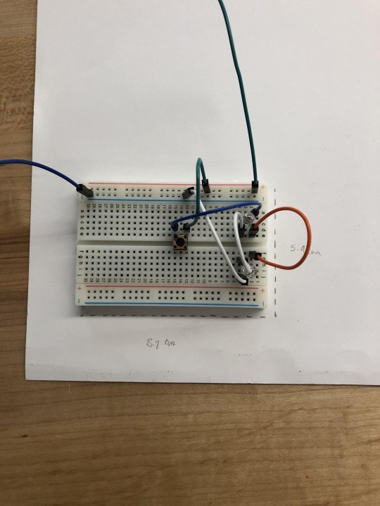
Project 1: Breadboards Pt. 2
STEP 2: After I finished the circuitry of my breadboard, I got a piece of paper and cut out a stencil of my business card. I did this by going to an unused circuit board (the same size as my own) and tracing it with a pencil. I then used a ruler to measure the dimensions of my circuit board (8.7 cm x 5.4 cm). I decided to measure out 0.5 cm more space on each side of my business card to make sure my card would completely cover the circuit and then I cut the guide (dotted) lines I created to get the shape of my business card. Here is a picture of that process:
STEP 3: I first started to encounter difficulty when I tried to place my business card over the circuit board I created. The issue was the fact that I had so many wire loops sticking out and no way to pin them down. I solved this issue by ironically, using more wires. I took a medium length M-M wire and weaved it into the wire loops on the lower side of my circuit board. I then took a medium length F-F wire, weaved the wire along the upper wire loops, and connected the M-M and F-F wires to each other in the back of my circuit board thus pulling the major wire loops to the side of the board and flattening them so I could put my business card over the wires.
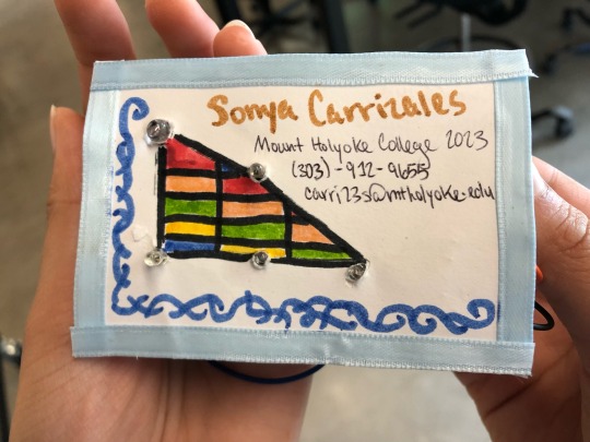
STEP 4: The last part of my project was designing the business card! First, I had someone help me push down the button to turn on the lights of my circuit while I marked the rough location of those lights. I used a wire cutter to actually poke out the holes for my lights (probably not the safest option). Then, I cut some blue ribbon and pasted it around the business card. I proceeded to design my card using markers and I wrote out my information.
Here is a picture of my final project! I was very happy about the way this one turned out! Despite a few difficulties I faced with determining where to cut the holes on the business card for my lights, or how to push the wires on my breadboard down, with perseverance I was able to figure out solutions to said issues and create a project I’m very proud of :)

0 notes
Text
Project 1: Breadboards Pt 1.
Here is a video of my circuitry for the buisness card!
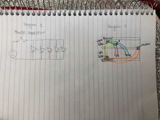
STEP 1: The first step of this project was wiring the lights in a triangle shape and making sure the button worked for each light. The wiring went quite well for this project, considering the fact that I was able to figure out the circuitry necessary to light up all five lights without any help. The only way I was able to get all the lights to light up was by sending power to the lights on opposite sides of the circuit board. For instance, after connecting a button to the first light (orange highlight), I started my circuitry by sending power from the left side (light 1) to the right side (light 2) of the board (yellow highlight). I then went and wired the right side (light 2) to the lower right side (light 3) (green highlight). From that point forward, I wired the right side (light 3) to the remaining lights on the left side (light 4) (blue highlight) and (light 5) (pink highlight). For clarity purposes, here’s one circuit diagram (Diagram 1) demonstrating the parallel connection of my circuitry, and another diagram (Diagram 2) which depicts the wiring in my circuitry which I explained above:
0 notes