
Don't wanna be here? Send us removal request.
Statistics
We looked inside some of the posts by stepper1128 and here's what we found interesting.
Average Info
Notes Per Post
0
Likes Per Post
0
Reblog Per Post
0
Reply Per Post
0
Time Between Posts
20 days
Number of Posts By Type
Text
16
Last Seen Tumblr Blogs


Fun Fact
Users from the US are the majority of Tumblr visitors.
Text
Main structure and design features of CNC spindle motor
1.Definition of CNC spindle motor CNC spindle motor is the core component of CNC machine tools, responsible for driving the spindle to rotate and perform cutting processing. The spindle motor generates rotational torque through electromagnetic induction, driving the spindle to rotate at high speed, thereby achieving high-precision processing operations. The electric spindle directly integrates the motor into the spindle, realizing efficient operation of mechatronics, significantly reducing the driving process, making the structure more compact and the noise lower, while also achieving higher mechanical efficiency, better precision and smaller vibration amplitude.

2.Operation mode of CNC spindle motor
1.Operation mode with variable speed gear: multi-stage mechanical speed change is achieved through the gearbox, which is suitable for occasions requiring large torque and speed change requirements. The advantages of this method are compact structure and high transmission efficiency, but the disadvantages are that it increases the complexity of the hydraulic system and the vibration and noise caused by the transmission are large.
2.Belt drive operation mode: Synchronous toothed belt drive is used, which is suitable for small CNC machine tools. The advantages are simple structure and ability to suppress vibration and noise, but the transmission ratio is inaccurate, which is suitable for small and medium power situations. 3. Direct drive of speed-regulating motor (electric spindle): The motor is directly connected to the spindle, which belongs to the direct drive structure. The advantage of this method is that it simplifies the structure of the spindle box and the spindle and improves the rigidity of the spindle components, but the heating of the motor has a greater impact on the spindle. It is suitable for small parts processing but not suitable for heavy cutting.
3.The main structure of CNC spindle motor 1. Spindle box: The spindle box is an important component of the spindle of CNC machine tools. Its main function is to support the spindle and withstand cutting force, radial force and axial force. The spindle box is generally made of high-strength materials and has sufficient rigidity and stability. 2. Spindle motor: The spindle motor is a key component that drives the spindle to rotate. It usually uses an AC servo motor or an ordinary AC motor, which has the advantages of high precision, high speed and high torque. 3. Bearing: The bearing is used to support the spindle and withstand radial force and axial force. The spindle of CNC machine tools generally uses rolling bearings, which have the advantages of low friction, high speed and high precision. 4. Seals: Seals are used to prevent cutting fluid and dust from entering the spindle box, maintaining the cleanliness and lubrication performance of the spindle box. Seals are generally made of rubber materials, which have the advantages of high temperature resistance, wear resistance and corrosion resistance. 5. Cooling device: Since the electric spindle generates a lot of heat when running at high speed, the cooling device ensures that the temperature of the spindle unit is maintained within an appropriate range. The cooling device usually includes two methods: water cooling and air cooling. The water-cooled spindle uses water circulation cooling, while the air-cooled spindle relies on fans to cool down. 6. Drive module: The drive module is used to control the speed change function of the spindle to ensure that the rotation speed and torque of the spindle meet the processing requirements. The drive module is usually integrated with the spindle unit housing to achieve precise control. 7. Speed and angular displacement sensors: These sensors are used to measure the rotation speed and angular position of the spindle, and timely feedback information to the CNC system to ensure the accuracy and stability of processing. 8. Inner tapered hole and end face design: The front end of the spindle is designed with an inner tapered hole and end face, which is convenient for the installation and use of the tool. The design of the inner tapered hole and end face directly affects the clamping force and stability of the tool.

4.Design features of CNC spindle motors
1.High speed and power density: CNC spindle motors usually have high speed and power density. For example, the rated speed of the 4.5KW manual high-gloss ultra-precision electric spindle can reach 24000rpm, ensuring stable operation at high speed. 2. Low noise and vibration: In order to reduce noise and vibration, the cooling system and dynamic balancing characteristics are taken into consideration during the design. For example, the JGD-125-2 model electric spindle controls the maximum speed noise within 70dB through the water cooling system, and the dynamic balancing accuracy reaches 3mg, ensuring stability at high speed. 3. High precision and stability: The design of CNC spindle motors focuses on precision and stability. For example, some models of electric spindles are equipped with high-precision bearings and cooling systems, and the axial/radial runout accuracy can reach within 0.002mm. The cooling system controls thermal deformation to ensure processing accuracy. 4. Bearing type: Common bearing types for electric spindles include ceramic ball bearings, hydrostatic bearings and magnetic bearings. Ceramic ball bearings are lightweight and high hardness, suitable for machining centers and milling machines; hydrostatic bearings are known for their high rotation accuracy and low wear; magnetic bearings work in a non-contact manner, with high-speed performance and accuracy, but at a higher cost. 5. Cooling system: In order to cope with the heat generated by high-speed operation, the design of the cooling system is crucial. For example, the JGD-125-2 model uses a water cooling system to ensure constant temperature processing of the spindle and improve processing stability.
0 notes
Text
What are the design requirements for linear stepper motors?
1.Basic principle of linear stepper motors The basic principle of linear stepper motors is to convert rotational motion into linear motion. The linear stepper motor contains a magnetic rotor core inside, which interacts with the pulsed electromagnetic field generated by the stator to generate rotation. Specifically, the linear stepper motor usually adopts a screw and a nut meshing method, and prevents the screw and the nut from rotating relative to each other in some way, so that the screw moves axially.

2.Basic structure of linear stepper motors The basic structure of linear stepper motors includes main parts such as stator assembly, rotor assembly, front cover, rear cover, and screw assembly. Specifically, there are multiple first teeth and first tooth slots on the inner circumference of the stator assembly, and multiple second teeth and second tooth slots on the outer circumference of the rotor assembly. A part of the second tooth corresponds to the first tooth, and a magnetic strip is installed in the first tooth slot, and another part of the second tooth corresponds to the magnetic strip.
3.Durability of linear stepper motors
1.Service life: The service life of a linear stepper motor mainly depends on its use environment and the loss of mechanical parts. The motor itself has no brushes to wear, so its lifespan usually exceeds that of other mechanical parts in the system. The main factors affecting lifespan include workload, working environment, bearing quality, etc. For example, running the motor at or near maximum thrust will significantly affect its lifespan, while maintaining a thrust margin of more than 50% can extend the motor life. 2. Working environment: The working environment has a significant impact on the lifespan of the linear stepper motor. High humidity, chemicals, dirt, and heat will accelerate the loss of motor parts, thereby shortening the motor life. In addition, mechanical factors such as side loads on the shaft, unbalanced loads, and eccentricity during installation will also have an adverse effect on the motor life. 3. Care and maintenance: Regular care and maintenance can significantly extend the service life of the linear stepper motor. Maintenance measures include keeping the motor clean and avoiding oil, dust, and water pollution; regularly checking the wear of the bearings and replacing them in time; ensuring that the motor operates in a suitable environment to avoid high temperature and humidity; and reasonably controlling the supply voltage and current to avoid overload operation. 4. Design features: Linear motors have the advantages of high efficiency, high speed and compact design. Due to its contactless force transmission characteristics, the mechanical friction loss is almost zero, so there are few faults, maintenance-free, safe and reliable operation and long life.

4.Design requirements for linear stepper motors 1. Load capacity: The static and dynamic loads of the system need to be considered during design. Static load refers to the maximum thrust that the motor can withstand when it is stationary, while dynamic load refers to the maximum thrust that the motor can withstand when it is moving. These two loads together determine the basic size and performance of the motor. 2. Operating speed: The operating speed of a linear motor is closely related to the lead of the screw. Engineers need to carefully select the appropriate lead of the screw according to the speed required by the system. Generally speaking, it is recommended to use a screw with a smaller lead when the speed is low, and a screw with a larger lead should be selected for optimal performance when the speed is high. 3. Accuracy requirements: The accuracy requirements of the system include linear accuracy and repeatability. Linear accuracy refers to the error between the actual stroke and the theoretical stroke after the lead screw rotates multiple times, while repeatability refers to the accuracy with which the system can repeatedly reach the specified position. These indicators are critical to the performance of the system. 4. Backlash: Backlash is the relative axial movable amount of the lead screw and nut when they are stationary. As the working time increases, the backlash may increase, so special attention needs to be paid to backlash compensation or correction, especially in applications that require bidirectional positioning. 5. Installation and connection: When designing, it is also necessary to consider whether the installation method of the linear stepper motor meets the mechanical design requirements, how to connect the moving object to the nut, and the effective stroke of the lead screw and the matching driver. 6. Material selection: In the design process, the selection of materials is also very important. For example, the selection of parameters such as the magnetic flux density of the core, the current density of the coil, and the slot fill rate will affect the performance and efficiency of the motor. Too high a magnetic flux density will lead to increased iron loss, while too high a current density will increase the resistance and temperature rise of the coil. 7. Structural type: There are three main structural types of linear stepper motors: external drive type, through-shaft type and fixed-shaft type. Each structural type has its specific application scenarios and design requirements.
0 notes
Text
How to improve the stability and service life of right-angle planetary gearboxes
1.Introduction to right-angle planetary gearboxes Right-angle planetary gearboxes are gearboxes used for deceleration or acceleration transmission, with the characteristics of high transmission efficiency, small size, low noise and long service life. Its core structure includes sun gear, planetary gear and inner ring gear. This structure can achieve high-efficiency transmission, and at the same time has high load-bearing capacity and long service life.

2.Working principle of right-angle planetary gearboxes The working principle of right-angle planetary gearboxes is based on the special structure of planetary gears, and its core lies in the rotation and revolution of planetary gears. The axis of rotation of the planetary gears is not fixed, but is installed on a rotatable bracket, which is called a "planet carrier". The planetary gears can not only rotate around their own axis (rotation), but also rotate around the axis of other gears with the planet carrier (revolution). This movement is similar to the movement of planets in the solar system.
3.Methods for improving the stability of right-angle planetary gearboxes
1.High-quality materials: The right-angle planetary gearbox is made of high-quality materials, with precise gear engagement, low noise, and no obvious wear after long-term use, thereby improving the stability of the equipment. 2. Precision manufacturing process: Through high-precision CNC machining technology, such as gear grinding and gear hobbing, the gear tooth profile accuracy is ensured to reach IT5-IT6 level, so that the gear is evenly stressed during the meshing process, vibration and noise are reduced, and a stable transmission ratio is maintained. 3. Compact structural design: The output shaft of the right-angle planetary reducer is at a 90-degree angle to the input shaft. This design enables the reducer to achieve efficient power transmission in a limited space, which is particularly suitable for occasions with limited space. 4. High transmission efficiency: The multi-stage transmission design of the right-angle planetary reducer enables it to have a higher transmission efficiency, usually up to more than 90%, reducing energy loss and improving the stability and reliability of the equipment. 5. High load-bearing capacity: The multi-point contact planetary gear system design enables the right-angle planetary reducer to have a higher load-bearing capacity, which is suitable for heavy-load occasions and further improves the stability of the equipment.

4.Methods to extend the life of the right-angle planetary gearbox 1. Regular cleaning and maintenance: Keeping the inside of the gearbox clean is the basic condition for extending its service life. Any impurities or dirt entering the gearbox will affect and damage its rotating system, thereby reducing its service life. Regularly clean the oil and dust on the equipment to ensure that the inside of the gearbox is clean.
2.Control the working temperature: Maintaining the normal working temperature of the gearbox can prevent the deformation of parts due to excessive temperature difference, ensure the normal operation of the gears, prevent excessive noise, and thus extend the service life. For gearboxes working in high temperature environments, heat dissipation devices such as radiators or cooling fans can be installed to avoid excessive temperatures that accelerate the failure of lubricants and wear of parts.
3.Reasonable use of lubricants: The use of lubricants is essential to the operation of gearboxes. Delayed use of lubricants or use of inferior oils will cause immeasurable damage to the gearbox. Regularly injecting an appropriate amount of lubricants and ensuring their quality can effectively reduce friction and wear.
4.Avoid overload and impact: Strictly use the rated torque and power of the gearbox to avoid overload operation. In the mechanical system design stage, the workload should be accurately calculated and a gearbox of appropriate specifications should be selected. Reduce the impact load during starting and stopping, adopt a slow and smooth operation method, and protect internal components. 5. Check and replace worn parts: Regularly check the relevant parts of the gearbox, such as oil seals and gaskets, and replace damaged or loose parts in time to ensure the normal operation of the gearbox. 6. Follow the instruction manual: Use the gearbox correctly in accordance with the instruction manual and avoid arbitrary and improper use, which can minimize the damage to the parts in the machine.
Source:https://www.steppernews.com/2025/03/how-to-improve-stability-and-service.html
0 notes
Text
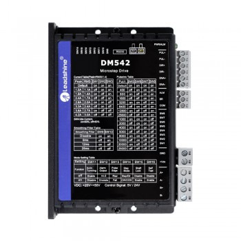
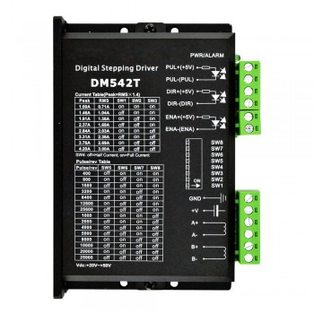
Main functions and maintenance methods of stepper motor drivers
1.Introduction to the working principle of stepper motor drivers The stepper motor driver is an actuator that converts electrical pulses into angular displacement. The stepper motor driver accurately controls the number of steps, speed and direction of the stepper motor by receiving pulse signals from the control system. The working principle of the stepper motor is to convert the electrical pulse signal into angular displacement, and control the angular displacement by controlling the number of pulses, thereby achieving precise control of the motor position.
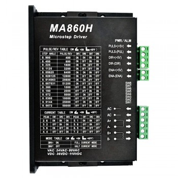
2.Main components of stepper motor drivers 1.Microprocessor: As the core component of the stepper motor driver, it is responsible for receiving input signals, processing control algorithms and outputting control signals. Microprocessors usually use high-performance, low-power single-chip microcomputers or DSP chips, with rich peripheral interfaces and powerful processing capabilities. 2.Power amplifier: Responsible for amplifying the control signal output by the microprocessor into the driving current required by the motor. The power amplifier usually uses switching power supply technology, with the characteristics of high efficiency, high power density and low noise, and has over-current, over-voltage, short-circuit and other protection functions to ensure the safe and stable operation of the motor. 3.Drive circuit: The bridge connecting the microprocessor and the power amplifier is responsible for converting the control signal into a signal that the motor can recognize.
3.The main functions of the stepper motor driver 1.Pulse distribution: The stepper motor driver controls the movement of the motor by receiving the control signal and converting it into the drive signal of the motor. Specifically, the ring distributor in the driver receives the pulse signal, direction signal and offline signal, and accurately controls the transistor in the power amplifier to turn on according to the instruction of the pulse signal, so as to drive the coil of the stepper motor to be energized. 2.Power amplification: The stepper motor driver provides sufficient power to drive the motor by amplifying the motor drive signal to ensure that the motor can operate normally. The drive module amplifies the motor drive signal and provides sufficient power to the motor to ensure that the motor moves in the specified step length and direction. 3.Precision control: The stepper motor driver achieves precise control of the motor position and speed by accurately controlling the step angle of the motor. This precise control makes stepper motors widely used in CNC equipment. 4.Protection function: The stepper motor driver also has a variety of protection functions, such as undervoltage lockout, overtemperature protection, etc. These functions can improve the stability and safety of the system.
4.Maintenance methods of stepper motor drivers 1.Regular inspection and cleaning: Regularly check whether the connection wires, power cords and switch power cords of the stepper motor driver are broken, and ensure that all connections are firm and there is no short circuit. At the same time, keep the surface of the driver clean to avoid dust accumulation affecting the heat dissipation effect. 2.Power supply system inspection: Use a digital multimeter to check the connection wires of the driver power supply system terminals and the working voltage of the power supply system to ensure that the power supply system is normal, without voltage abnormalities or insufficient power supply. 3.Heat dissipation management: Check whether the heat dissipation setting is proper and ensure that the driver has enough heat dissipation space. You can add heat dissipation equipment such as fans or heat sinks, and ensure that the working environment temperature does not exceed the specified range. 4.Parameter setting check: Check whether the current setting of the driver is correct to ensure that it does not exceed the rated current of the motor. Adjust the pulse width and the maximum step rate of the motor to avoid problems such as inter-turn and lost steps when the motor moves. 5.Environmental management: The stepper motor driver should be stored in a clean, well-ventilated environment with an ambient temperature of -40 to 50°C and a relative humidity not exceeding 95%. Avoid contact with corrosive, flammable gases, oil mist, dust and other impurities. 6.Regular maintenance: Regularly check the various components of the driver, including power cord, fuse, enable signal line, etc., to ensure their normal operation. Replace severely worn parts such as bearings in a timely manner. 7.Troubleshooting: If the driver fails, determine whether it is a common fault such as overvoltage, undervoltage protection, overcurrent, overtemperature, etc. according to the indication of the LED or other methods, and refer to the instructions for use for corresponding processing.
0 notes
Text
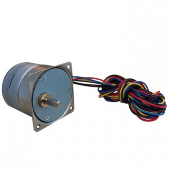
Control method and application of permanent magnet stepper motor
1.Working principle of permanent magnet stepper motor The working principle of permanent magnet stepper motor is based on magnetic field interaction and electromagnetic induction. When currents of different phases are applied to the stator winding, a rotating magnetic field is generated. This rotating magnetic field interacts with the permanent magnets on the rotor, causing the rotor to be attracted from one pole pair to another in sequence, thereby realizing rotational motion. By changing the power-on state, the rotation direction and step angle of the motor can be controlled.

2.Structural characteristics of permanent magnet stepper motor 1.Design of rotor and stator: The rotor of a permanent magnet stepper motor is composed of permanent magnets, while the stator usually contains electromagnetic coils or windings. The permanent magnets on the rotor are usually magnetized radially with multiple poles, while the pole pieces on the circumference of the stator inner hole are arranged in a claw-shaped annular symmetry. 2.Magnetic isolation sheet and annular winding: The stator and rotor of the entire motor are axially divided into two sections, separated by a magnetic isolation sheet in the middle, and the two sections are separated by a step angle. There are annular windings on each stator section, and these windings are usually connected in reverse series. 3.Cost and efficiency: The cost of permanent magnet stepper motors is relatively low, and the control power is small and the efficiency is high. Since the rotor is a permanent magnet, there is torque holding force when there is no excitation, which allows the motor to maintain a certain torque even in the non-excitation state. 4.Step angle and step angle: The step angle of permanent magnet stepper motors is large, and common step angles include 5.625°, 7.5°, 11.25° and 15°.
3.Control method of permanent magnet stepper motors 1.Control (FOC): Vector control is one of the most widely used permanent magnet synchronous motor control strategies. It is based on the mathematical model of the motor and space vector modulation technology, and achieves precise control of the motor by controlling the rotor magnetic field and stator current of the motor. 2.Direct torque control (DTC): DTC uses Bang-Bang control (hysteresis control) to generate PWM signals to optimally control the switching state of the inverter, thereby obtaining torque control with high dynamic performance. Its basic operation is to transmit the error between the set value and the actual value of the flux torque to the hysteresis comparator, and obtain the appropriate motor space vector through the offline operation switch table to realize the speed control of the motor. 3.Magnetic control: The purpose of weak magnetic control is to increase the speed of the DC motor. By reducing the excitation current of the motor and reducing the excitation flux, the motor speed can be increased to above the rated speed under the condition of ensuring voltage balance. For permanent magnet synchronous motors, weak magnetic control weakens the air gap flux by increasing the demagnetization component of the stator current, thereby achieving the purpose of increasing the motor running speed.
4.Common applications of permanent magnet stepper motors 1.In the field of industrial automation, permanent magnet stepper motors are often used to drive various mechanical equipment to achieve precise control of production lines. For example, in automated assembly lines, automated packaging lines, and automated conveyor lines, permanent magnet stepper motors can drive conveyor belts, elevators, rotary tables and other equipment to improve production efficiency and accuracy. 2.In the field of robotics, permanent magnet stepper motors are widely used in industrial robots, service robots, drones and other equipment. Due to its high efficiency, high response speed and high torque density, permanent magnet stepper motors can provide powerful power support for robots and achieve high-precision and high-speed motion control. 3.In the field of textile machinery, permanent magnet stepper motors can be used in textile machines, looms and dyeing and finishing equipment. It can replace traditional AC motors, achieve precise control of textile machinery, and improve production efficiency and product quality. 4.In the field of printing machinery, permanent magnet stepper motors are used in equipment such as printing machines, paper cutters and folding machines. It can achieve precise control of printing machinery and improve printing speed and printing quality. Household appliances and agricultural machinery 5.In the field of household appliances, permanent magnet stepper motors gradually replace traditional AC asynchronous motors and are used in equipment such as air conditioners, washing machines, refrigerators and televisions. 6.In the field of agriculture, permanent magnet stepper motors are also widely used in agricultural machinery and irrigation equipment to improve the efficiency and reliability of equipment.
0 notes
Text
How to debug the performance of integrated servo motors
1.Brief introduction of integrated servo motors Integrated servo motors are devices that integrate motors and servo controllers. They combine the traditional separate structures of motors and servo controllers into one, greatly simplifying the system design and installation process. Integrated servo motors have the advantages of small size, high power density, and fast response speed, and are widely used in the field of industrial automation.

2.Structural composition of integrated servo motors Integrated servo motors consist of motors, servo controllers, encoders, and communication interfaces. The motor is responsible for rotation, the servo controller is responsible for controlling the speed and position of the motor, the encoder is used to feedback the actual rotation of the motor, and the communication interface is used to interact with other devices. The servo controller calculates the speed and position error of the motor by receiving the feedback signal from the encoder, and adjusts the power supply voltage and current of the motor according to the set control algorithm (such as PID control algorithm) to achieve precise control of the motor.
3.Advantages of integrated servo motors 1.High precision: The reducer and encoder of the integrated servo motor are integrated in a closed body, which can effectively reduce the transmission error and improve the control accuracy. 2.High efficiency: Since all components in the integrated servo motor are integrated, the loss of energy conversion is reduced and the energy utilization efficiency is improved. 3.Easy to install: The integrated servo motor does not require additional transmission devices and mechanical structures, and can be directly installed on the equipment, reducing the difficulty and time cost of installation. 4.Compact structure: Compared with traditional servo systems, integrated servo motors have a more compact structure, which can greatly reduce the space occupied by the equipment and optimize the layout of the equipment. 5.Fast response: The integrated servo motor has a higher response speed and can achieve precise position control and synchronization tasks in a short time. 6.High continuous torque: It has high continuous torque or effective torque in a wide speed range, which is suitable for application scenarios requiring high loads. 7.Low torque pulsation: The torque pulsation of the integrated servo motor is low, which can provide more stable output. 8.High overload capacity: It has high overload capacity in a short time and can provide greater torque output when needed.

4.Performance debugging method of integrated servo motor 1.Determine the command mode: The servo motor can be controlled by digital pulse control and analog signal control. Digital pulse control sends pulse command signals of "pulse/direction" or "CW/CCW" type, and the servo drive works in position control mode. This method is simple and not easy to interfere, but the response is slightly slow. Analog signal control sends +/-10V analog voltage commands, and the servo drive works in speed control mode. It responds quickly but is sensitive to interference and the debugging is more complicated. 2.Initialization settings: According to the actual situation of the motor and load, adjust the initial parameters of the servo drive, such as gain, integration time, etc. The settings of these parameters directly affect the performance and stability of the motor. 3.Position and speed calibration: Use the position and speed calibration tool to ensure that the motor moves at the expected position and speed. This step is the key to ensure the performance of the motor. 4.Load test: Test the performance of the motor under actual load and adjust the parameters to optimize the performance. Through load testing, the actual working capacity and stability of the motor can be verified. 5.Troubleshooting: When encountering a problem, find out the cause of the fault and solve it by checking components such as circuits, sensors and drivers. Troubleshooting is an important step to ensure the normal operation of the system. 6.Continuous monitoring and adjustment: Regularly check the operating status of the motor and adjust the parameters as needed to ensure that the system is always in the best condition. Continuous monitoring and adjustment can ensure the long-term stable operation of the system.
Similar articles:https://pomana.hatenablog.com/entry/2024/11/08/180219
0 notes
Text
Technical advantages of high temperature stepper motors
1.What is a high temperature stepper motor High temperature stepper motors are motors specially designed to work in extremely high temperature environments and can maintain good performance in high temperature environments. Compared with ordinary motors, high temperature stepper motors use special materials and designs to adapt to high temperature environments. These motors usually use high temperature resistant magnetic materials and special insulated wires to ensure that they will not demagnetize or be damaged at high temperatures.

2.The main structure of high temperature stepper motors 1.Stator structure: The stator of a stepper motor is usually stacked with high magnetic permeability silicon steel sheets to form multiple stator teeth. Two sets of coils are wound around these stator teeth, and a rotating magnetic field is generated by controlling the power-on timing of the coils to drive the rotor to rotate. 2.Rotor structure: The rotor is usually made of permanent magnetic material, and its structural design and material selection enable it to remain stable in high temperature environments. The design of the rotor enables it to withstand high temperature environments and will not be damaged by overheating.
3.Technical advantages of high temperature stepper motors 1.High temperature resistance: High temperature stepper motors use special materials and structural designs to operate normally under high temperature conditions and are not affected by ambient temperature. This type of motor usually uses high-temperature resistant materials and high-temperature resistant designs, can operate stably in high-temperature environments, and will not be damaged by overheating. 2.High-precision positioning: The high-temperature stepper motor has a high-precision positioning function and adopts advanced control technology to accurately control the rotation angle and movement speed of the motor to achieve precise position positioning. In a high-temperature environment, it can still maintain good positioning performance, providing reliable guarantee for high-precision operation. 3.Low noise and low vibration: The design of the high-temperature stepper motor not only takes into account the special requirements of the high-temperature environment, but also focuses on reducing the impact of noise and vibration. It adopts advanced vibration reduction technology and noise control measures, so that under high-temperature working conditions, the motor can still maintain a low-noise and low-vibration operating state, which is very important for high-temperature fields that require quiet and stable operation. 4.High-efficiency and energy-saving: The high-temperature stepper motor has the characteristics of high efficiency and energy saving, which can effectively reduce energy consumption and maintenance costs. This motor can still maintain efficient operation in a high-temperature environment, reducing energy waste and reducing the cost of use. 5.Easy to install and maintain: The high-temperature stepper motor has a simple and compact structure, is easy to install and maintain, and reduces the cost of use. This design makes the motor more convenient during installation and maintenance, reducing the frequency of maintenance and replacement of the motor. 6.Adapt to harsh environments: High-temperature stepper motors can be customized with special protection levels to adapt to harsh environments. It can adapt to various high-temperature application scenarios, such as ovens, furnaces, hot presses, hot air guns, etc., and can also operate stably in low-temperature environments.

4.Application fields of high-temperature stepper motors 1.Aviation field: In the aviation field, high-temperature stepper motors are mainly used for flight control, positioning and orbit control. Its high precision and low noise characteristics enable stable operation in high temperature and vacuum environments, ensuring the reliability and accuracy of the system. 2.Satellite field: In satellite systems, high-temperature stepper motors are used for positioning and orbit control, and can adapt to high temperature and vacuum environments to ensure the long-term stability and efficiency of satellite systems. 3.Industrial applications: In the industrial field, high-temperature stepper motors are suitable for various application scenarios that require high-temperature operation, such as ovens, furnaces, hot presses and hot air guns. Its high-temperature resistant design and high efficiency and energy saving characteristics enable stable operation in these environments, extend service life and reduce maintenance costs. 4.Laboratory environment: In special environments such as high-temperature laboratories, high-temperature stepper motors can work stably, provide precise control and positioning functions, and are suitable for various scientific research and experimental needs. 5.Extreme environment: In some extreme environments, such as high and low temperature alternation, low air pressure, salt spray and other environments, high-temperature stepper motors can also maintain stable operation, which is suitable for automated production needs in various complex environments.
Source:https://www.steppernews.com/2024/11/technical-advantages-of-high.html
0 notes
Text
Solutions to faults during operation of stepper motor drivers
1.Basic understanding of stepper motor drivers A stepper motor driver is an actuator that converts electrical pulses into angular displacements. It drives the stepper motor to rotate a fixed angle in the set direction by receiving control signals. The stepper motor driver is an important component of the stepper motor system, responsible for converting the control signal into the current and voltage required by the stepper motor to drive the motor for precise angular or linear displacement. The working principle of the stepper motor driver is to convert the input pulse signal into a drive current signal to control the angular displacement of the stepper motor. The speed of the motor is proportional to the pulse frequency, so the speed can be accurately adjusted by controlling the pulse frequency, and the positioning can be accurately achieved by controlling the number of pulses. The stepper motor driver has high positioning accuracy and stability, and can subdivide each step into smaller steps through the subdivision function, thereby improving positioning accuracy and stability.
2.The main structure of the stepper motor driver 1.Ring distributor. Generate the switching waveform signal processing of the motor in different states according to the requirements of the input signal. Perform PWM modulation on the switching signal waveform generated by the ring distributor and filter and shape the related waveform. 2.Protection circuit. When the winding current is too large, a shutdown signal is generated to shut down the main circuit to protect the motor driver and motor winding. 3.Sensor. Real-time monitoring of the position and angle of the motor, and the signal generation device is transmitted back.
3.Solutions to faults during operation of stepper motor drivers 1.The motor does not rotate or rotates slowly: The stepper motor driver needs to receive the correct pulse signal to control the motor rotation. If the motor does not rotate or rotates slowly, first check whether the pulse signal source is working properly, ensure that the driver input terminal is connected correctly, and check whether the motor wiring is correct to eliminate the motor itself. 2.Overheating: The stepper motor driver may overheat when working for a long time or overloaded. Improve the heat dissipation conditions, add fans or heat sinks, ensure that the working environment temperature is suitable, and avoid long-term overload operation. 3.Excessive noise: Abnormal noise during motor operation may be caused by bearing damage or loose internal parts. Check whether the motor bearing is damaged, re-tighten the loose internal parts, and adjust the driver current setting. 4.Overcurrent protection: The driver has an overcurrent protection function. If the output current exceeds the rated value, the driver will cut off the power supply to protect the motor and itself. Check the power supply and motor load, and readjust the current setting. 5.Communication error: If the driver and controller are controlled by communication, communication errors may indicate that the driver cannot work properly. Check the communication line and settings to ensure stable communication.
4.Precautions for using stepper motor drivers
1.Power management: The quality of the power supply directly affects the performance and power consumption of the driver. The ripple size of the power supply affects the accuracy of the subdivision, and the suppression ability of the power supply common mode interference affects the anti-interference of the system. Therefore, for applications with higher requirements, users must pay attention to improving the quality of the power supply. In addition, the installation of the driver should ensure good ventilation, and regularly check whether the cooling fan is running normally. 2.Signal line processing: When wiring the system, the principle of separating the power line (motor phase line, power line) from the weak current signal line should be followed to avoid interference with the control signal. When it is impossible to wire separately or there is a strong interference source, it is best to use shielded cable to transmit the control signal. Using a higher level control signal is also meaningful for resisting interference. 3.Initial operation check: Do not connect all the lines at the beginning. You can connect the most basic system first, and then complete all the connections after confirming that it is running well. Carefully observe the sound and temperature rise of the motor. If any abnormality is found, it should be stopped and adjusted immediately. 4.Environmental adaptation: Due to the drastic changes in the storage and transportation environment temperature, condensation or frost is easy to occur. At this time, the driver should be placed for more than 12 hours. After the driver temperature is consistent with the ambient temperature, it can be powered on. If stored in an unsuitable environment for a long time, the quality of the product should be retested before operation.
Source:https://medium.com/@porterbickford69/solutions-to-faults-during-operation-of-stepper-motor-drivers-7fc1e964767f
0 notes
Text
How to adjust the dip switch of the stepper motor driver
1.Explanation of stepper motor driver The stepper motor driver is an actuator that converts electrical pulses into angular displacement, which is mainly used to control the rotation and movement of the stepper motor. It realizes the drive of the motor by converting the control signal into the drive signal of the motor. The stepper motor driver is generally composed of a pulse generator, a power module, a signal decoder and a drive module. The pulse generator is used to generate a control signal (pulse signal) to control the movement of the motor; the power module provides power to the motor so that the motor can operate normally; the signal decoder converts the pulse signal into a motor drive signal to control the operation of the motor; the drive module is used to amplify the motor drive signal to provide sufficient power to drive the motor.

2.Classification of stepper motor drivers 1.Voltage driver: It controls the speed and position of the stepper motor by changing the drive voltage. This driver is characterized by simple structure and low cost, but poor dynamic performance, easy to heat up and lose step. 2.Constant current driver: It drives the stepper motor by controlling the current to ensure that the current of the motor remains constant during operation. This type of driver is characterized by good dynamic performance and low heat generation, but the structure is relatively complex and the cost is high. 3.Microstep driver: It is a high-precision drive method that achieves more detailed position control by dividing the basic step of the stepper motor. This driver has the characteristics of high precision, low vibration and low noise, and is suitable for application scenarios with high precision requirements. 4.Closed-loop driver: By adding an encoder or other sensor to achieve real-time feedback on the position of the stepper motor, high-precision position control is achieved. This driver has the characteristics of high precision, high dynamic performance and low step loss rate, but the structure is relatively complex and the cost is high.
3.Reasons for stepper motor driver alarm 1.Power supply problems are one of the common reasons for stepper motor driver alarms. This includes unstable power supply voltage, too high or too low power supply voltage, poor power supply line contact, and power switch failure. Solutions to these problems include checking whether the power supply voltage meets the requirements, adjusting the power supply voltage in time, repairing or replacing the power supply line contact, and checking and replacing the power switch. 2.Motor problems may also cause stepper motor driver alarms, including motor damage, poor contact between the rotor and stator, and winding short circuit. Solutions to motor failures may include checking whether the motor is overheating and whether it needs to be replaced or maintained, such as cleaning and lubrication. 3.Control signal problems are also an important factor, including poor contact of the control signal line, controller failure, and unstable control signal voltage. Solutions to these problems may involve repairing or replacing the control signal line, checking and replacing the controller, and adjusting the control signal voltage. 4.Problems with the driver itself, such as a damaged or improperly adjusted driver, can also cause alarms. Solving these problems may require replacing the driver or adjusting the driver settings.

4.How to adjust the stepper motor driver dip switch 1.Understand the basic principles of stepper motor drivers A stepper motor driver is an electronic device used to control stepper motors. It converts current into signals that the stepper motor can understand, thereby driving the motor to rotate precisely. Before adjusting the dip switch, you need to understand the basic principles of the stepper motor driver. 2.Determine the working mode and parameter settings Before adjusting the dip switch of the stepper motor driver, you first need to determine the working mode and parameter settings. The working mode can be full-step mode, half-step mode or micro-step mode; parameter settings include step angle, acceleration, drive current, etc. 3.Consult the instruction manual of the stepper motor driver Stepper motor drivers are usually equipped with an instruction manual, which contains detailed parameter settings and information about the dip switches. Before making adjustments, read the instruction manual carefully to understand the location and corresponding functions of the dip switches. 4.Locate and adjust the dip switches According to the instruction manual of the stepper motor driver, locate the dip switches on the driver. Dip switches are usually a row of small switches that can be set to different functions and parameters by toggling. Before adjusting the dip switches, it is recommended to turn off the power supply to avoid short circuits or other damage to the circuit. 5.Adjust the dip switches as needed Adjust the dip switches from one position to another as needed. When adjusting the dip switches, carefully check the information in the instruction manual to ensure that they are adjusted to the correct position. Some dip switches may have multiple options, while others may only have two options (on/off). 6.Start and test the stepper motor driver After the adjustment is completed, reconnect the power supply and start the stepper motor driver. According to the working mode and parameter settings of the driver, perform corresponding tests to ensure that the motor can rotate as expected. If other parameters need to be adjusted, you can refer to the instruction manual again and repeat the above steps. 7.Test and application of the adjusted stepper motor driver Once the dip switches of the stepper motor driver are successfully adjusted, some tests and practical applications can be performed. In the test, you can verify whether the set working mode and parameters are as expected. In the application, you can connect the stepper motor driver to the corresponding equipment or system to achieve the desired functions and performance.
Source:https://www.steppernews.com/2024/09/how-to-adjust-dip-switch-of-stepper.html
0 notes
Text
Methods for optimizing the performance of hybrid stepper motors
1.Definition of hybrid stepper motors Hybrid stepper motors are designed by combining the advantages of permanent magnet stepper motors and reactive stepper motors. Through a specific structural design, it achieves the complementary advantages of high torque of permanent magnet stepper motors and high precision of reactive stepper motors. Hybrid stepper motors are divided into two-phase, three-phase and five-phase, of which the step angle of two-phase is generally 1.8 degrees, the step angle of three-phase is generally 1.2 degrees, and the step angle of five-phase is generally 0.72 degrees. The rotor of this motor is magnetic, so the torque generated under the same stator current is greater than that of reactive stepper motors. In addition, the step angle of hybrid stepper motors is usually small, which makes it widely used in economical CNC machine tools. Although the structure of the hybrid rotor is more complex, the rotor inertia is large, and its speed is lower than that of the reactive stepper motor, its high precision and high torque characteristics make it the preferred choice in many applications.
2.Installation requirements for hybrid stepper motors 1.Determine the installation location: First, you need to choose a suitable location for installation based on the actual needs and space limitations of the equipment. At the same time, you must also consider the connection method and location of the stepper motor and other components (such as transmission devices, sensors, etc.) to ensure stable installation and normal operation. 2.Connect the power supply and controller: Before installing the stepper motor, you need to connect the power supply and controller correctly. Stepper motors are usually powered by a DC power supply, and you need to pay attention to the matching of voltage and current to ensure the stability and safety of the power supply. 3.Install the driver and controller: The motion control of the stepper motor is achieved through the driver and controller. The driver converts the current signal provided by the power supply into a control signal that the stepper motor can accept, while the controller is responsible for giving the corresponding step pulse signal. During the installation process, the driver and controller need to be correctly installed on the equipment and connected to the stepper motor according to the wiring diagram. 4.Connect external devices: According to actual needs, the stepper motor may need to be connected to some external devices, such as sensors, encoders, etc. These devices can provide feedback signals to help control the movement of the stepper motor and improve control accuracy and stability. During the installation process, it is necessary to ensure that these external devices are connected to the stepper motor and controller normally, and the signal transmission is correct. 5.Perform basic debugging and fine debugging: After the installation is completed, perform basic debugging on the stepper motor, check whether the power supply and controller are normal, and ensure that the circuit connection is correct. Then, send a pulse signal to the stepper motor through the controller, observe the movement of the stepper motor, and check whether there is any abnormality. After the basic debugging is completed, some fine debugging work can be performed to improve the performance and control accuracy of the stepper motor.
3.Cooling method of hybrid stepper motor 1.Air cooling: Increase the air flow around the motor by installing a fan or heat sink to accelerate the dissipation of heat. This method is suitable for situations where the motor capacity is not very large. Through the fan-type radial and axial mixed ventilation system, the motor temperature can be effectively reduced. 2.Liquid cooling: Set up a liquid cooling system inside the motor to transfer the heat inside the motor to the outside through liquid to accelerate the dissipation of heat. This is a very effective heat dissipation method, mainly used in occasions that require long-term continuous work. 3.Hydrogen cooling: Make the rotor and stator wires hollow, then compress the hydrogen and compress it into the conductor to take away the heat. Hydrogen cooling is more effective than air cooling, but it may be more complicated to implement. 4.Current reduction method: Reduce the heat generated by the motor by reducing the drive current of the stepper motor to achieve the purpose of heat dissipation. This method is suitable for situations where the performance requirements of the motor are not particularly high. 5.Optimize the design structure: By optimizing the design structure of the stepper motor, the heat generation inside the motor can be reduced, thereby reducing the temperature of the motor. This includes improving the material selection of the motor, optimizing the magnetic field design, etc. 6.Environmental control: Reduce the operating temperature of the motor by controlling the ambient temperature, reducing the motor load, reducing the motor current, etc., thereby reducing the heat generation. This method is suitable for situations where you have control over the working environment of the motor.
4.Methods for optimizing the performance of hybrid stepper motors 1.Adopt a new generation of controllers, introduce more advanced controllers, provide more precise step angle control and higher control accuracy. 2.Optimize the drive system, improve the motor drive circuit, and improve the power transmission efficiency and motor response speed. 3.Introduce a closed-loop control mechanism, adjust the rotation speed and position of the stepper motor in real time through the feedback mechanism, and improve the motion accuracy. 4.Improve the motor structure, optimize the design and material selection of the stepper motor, and reduce noise and vibration. 5.Provide more interfaces, increase communication interfaces and control options, and facilitate the integration of stepper motors with other devices. 6.Use finite element analysis for optimization design, analyze the electromagnetic field, temperature field, vibration, etc. of the stepper motor, and optimize the motor design. 7.Reduce the moment of inertia. Reducing the moment of inertia of the stepper motor can increase the response speed of the motor, thereby improving its dynamic performance. 8.Add overload protection. Adding overload protection to the stepper motor can prevent the motor from overloading, thereby protecting the motor from damage. 9.Optimize the motor material. Selecting the right material can increase the efficiency, stiffness and durability of the motor. 10.Improve the cooling system. A more efficient cooling system can prevent the stepper motor from overheating, thereby improving its reliability.
In addition, the performance of the hybrid stepper motor can be further improved by using micro-stepping drives to increase the resolution of the stepper motor, using high-precision magnets and winding materials, and optimizing control algorithms. These methods can be selected and combined according to specific applications and requirements to optimize the performance of the hybrid stepper motor.
0 notes
Text
Common faults and maintenance methods of brushless DC motors
1.Definition of brushless DC motors Brushless DC motors are a type of motor drive that combines synchronous motors and electronic control technology. They control the frequency of the stator's rotating magnetic field through electronic control (driver, including power supply and control), and feed back the motor rotor's speed to the control center for repeated correction to achieve a method close to the characteristics of a DC motor. This type of motor can control the motor rotor to maintain a certain speed within the rated load range when the load changes. Brushless DC motors do not have traditional brushes and commutators, so they have higher energy efficiency and longer service life, and are widely used in fields that require high performance and high reliability.

2.Components of brushless DC motors 1.Rotor: The rotor is the core part of the brushless DC motor and is composed of permanent magnets and iron cores. The magnetic field of the permanent magnet generates torque, which drives the rotor to rotate. The magnitude of the torque is related to the magnetic field strength of the permanent magnet. 2.Stator: The stator is the external part of the brushless DC motor and is composed of a coil and an iron core. When the coil is energized, it generates a magnetic field that interacts with the permanent magnet of the rotor to make the rotor rotate. The number and arrangement of the coils have a great influence on the speed and torque of the motor. 3.Sensor: The sensor is used to detect the rotor position and speed of the brushless DC motor and feed the signal back to the controller. Common sensors include Hall sensors and photoelectric sensors. 4.Controller: The controller is the intelligent part of the brushless DC motor and is used to control the speed and direction of the motor. It receives the signal from the sensor, adjusts it according to the set parameters, and cooperates with the motor's drive circuit to achieve precise control of the motor. 5.Drive circuit: The drive circuit converts the signal output by the controller into current and drives the motor through a power amplifier. The drive circuit achieves precise control of the rotor by controlling the magnitude and direction of the current.
3.Application areas of brushless DC motors 1.Equipment positioning applications: Brushless DC motors are suitable for applications that require precise control of position and speed, such as industrial control and automatic control applications, including process control, logistics control, and machine equipment control. These applications have special requirements for the dynamic response and torque of the speed, and may require the use of photoelectric and synchronous devices for speed measurement. 2.Variable load application areas: Brushless DC motors are also suitable for machines and equipment with variable loads, such as compressors of refrigerators, washing machines, air conditioners, etc. in daily household appliances, as well as engine equipment control, electric controllers, and oil pump control in the automotive field. These applications usually have high requirements for the dynamic response time and speed characteristics of the machine. 3.Continuous load application areas: Brushless DC motors are also suitable for equipment that needs to maintain load continuously, such as electric fans, hair dryers, agricultural pumps, etc. These devices have specific requirements for speed, but do not require overly precise control. Open-loop control is usually used, which is low in cost.

4.Common faults and maintenance methods of brushless DC motors 1.Power supply problems: Brushless motors require a stable power supply. If the power supply voltage is insufficient, the current is unstable, or the power supply fails, the brushless motor may stop working or run unstably. Solutions include ensuring that the power supply is stable, checking that the power cord is in good contact, and that the power supply voltage is stable. 2.Mechanical failure: The brushless motor needs to be properly mounted on the mechanical device and the rotation axis must be correct. If a mechanical failure prevents the motor from turning, the brushless motor will not work properly. Solutions include ensuring that the motor is properly mounted, the axis is correct, and any mechanical failures are repaired in a timely manner. 3.Sensor problems: Brushless motors usually use Hall sensors for position detection. If the sensor is damaged or cannot correctly detect the motor position, the brushless motor will not work properly. Solutions include checking and replacing damaged sensors. 4.Driver problems: The brushless motor driver may have faults, such as unstable power supply voltage, current sensor failure, etc., which may cause the motor to stop working or run erratically. Solutions include checking and repairing the driver circuit to ensure that it works properly. 5.Temperature problems: Brushless motors heat up during operation. If the temperature is too high, the motor may stop working or be damaged. Solutions include ensuring the motor is running at the proper operating temperature and taking cooling measures if necessary. 6.Magnet problem: The magnets of the brushless motor may be affected by external magnetic fields, causing the motor to run erratically or stop working. Solutions include ensuring the motor is away from objects that may generate strong magnetic fields, or replacing damaged magnets. Resistance problem: If the load driven by the motor is too heavy, it may cause the motor to stall or stop working. Solutions include reducing the load or checking the connection between the motor and the load to ensure smooth operation. 7.Controller failure: The brushless motor controller is a key component that controls the normal operation of the brushless motor. If the controller is broken, the brushless motor will not work properly. Repair steps include determining the controller failure, checking the power supply, control signal, driver circuit, and protection circuit to see if they are working properly.
0 notes
Text
Components of CNC stepper motor kit
1.What is a CNC stepper motor kit A CNC stepper motor kit is a complete set of equipment that includes stepper motors, drivers, power supplies, and necessary interface cards. It is specially designed for precise motion control of precision machinery such as CNC machine tools. This kit usually includes stepper motors, drivers, power supplies, and necessary interface cards, and is designed to provide high-precision, low-vibration, and high-reliability motion control solutions. As a special type of electric motor, the internal structure of a stepper motor consists of a rotor and a stator with a fixed number of poles. It can rotate accurately at a certain step angle without load, thereby achieving high-precision motion control.

2.Components of CNC stepper motor kit 1.The stator is the fixed part of the stepper motor, usually consisting of an iron core and a coil. When current flows through the coil, a magnetic field is generated, which interacts with the rotor magnetic field to drive the rotor to rotate. The design and material selection of the stator directly affect the performance of the stepper motor. 2.The rotor is the rotating part of the stepper motor, usually made of magnetic material. According to different electromagnetic field compositions, rotors can be divided into two types: magnetic rotors and permanent magnet rotors. The magnetism of magnetic rotors is provided by the stator, while permanent magnet rotors have their own permanent magnets. 3.The drive circuit is an important part of controlling the rotation of the stepper motor. It is responsible for applying current to the stator coil to make the motor rotate according to the set step angle. Common drive circuits include bipolar drive and four-phase interleaved drive. The direction and magnitude of the current are controlled to achieve precise control of the stepper motor. 4.The control system is the brain of the stepper motor. It is connected to the stepper motor through the control device and sends signals to the drive circuit to control the movement and position of the motor. The control system can be a closed-loop system based on hardware or an open-loop system based on software. Different control methods are selected according to specific application requirements.
3.How to choose the right kit 1.Clear application requirements: Before choosing a CNC stepper motor kit, you must first clarify your application requirements. This includes understanding the load characteristics, speed range, positioning accuracy and other key parameters of the required motor. According to different application scenarios, such as load application, positioning application, speed application, etc., choose the appropriate motor type. For example, for applications that directly drive the load, it is necessary to consider whether the torque and thrust of the motor are sufficient to overcome the load resistance; for scenarios that require precise position control, such as robot arms, CNC machine tools, etc., pay attention to the positioning accuracy and repeatability of the motor; for applications that require constant speed operation, such as fans, pumps, etc., it is necessary to ensure that the motor has stable speed control performance.

2.Choose the right motor type: Choose the right stepper motor type according to application requirements. Common stepper motor types include two-phase, three-phase and five-phase stepper motors. Two-phase stepper motors have a simple structure and low cost, and are suitable for occasions with light loads and low precision requirements; three-phase stepper motors have higher torque density and lower noise, and are suitable for occasions with heavy loads and high precision requirements; five-phase stepper motors have higher precision and lower vibration, and are suitable for applications with extremely high precision requirements. 3.Consider motor performance parameters: When choosing a stepper motor, you also need to pay attention to performance parameters such as torque, speed, positioning accuracy, repeatability, noise and vibration. These parameters directly affect the motor's driving ability, operating speed, position control ability, and the overall performance and service life of the equipment. 4.Weigh cost and maintainability: When choosing a stepper motor, you need to weigh cost and maintainability. Generally speaking, high-performance motors are more expensive, but may be more cost-effective in the long run. Choosing motors that are easy to maintain and service can reduce operating costs. 5.Brand and after-sales service: Choosing well-known brands and manufacturers that provide good after-sales service can ensure the quality of the product and the reliability of long-term use.
4.Conclusion CNC stepper motor kits can provide cost-effective, precise and easy-to-integrate solutions for motion control in CNC systems. They have advantages such as precise positioning, high torque at low speeds, and simple design. They are suitable for various CNC applications and can be used by users with different technical levels.
Source:https://steppermotor.pixnet.net/blog/post/159019012
0 notes
Text
How to minimize the heating of hybrid stepper motors?
As a digital actuator, hybrid stepper motors are widely used in motion control systems. When using hybrid stepper motors, many users feel that the motors are very hot when working, and they are skeptical whether this phenomenon is normal. In fact, heating is a common phenomenon of hybrid stepper motors, but what degree of heating is normal, and how to minimize the heating of hybrid stepper motors?

1.Understand the structure and principle of hybrid stepper motors For various hybrid stepper motors, the interior is composed of iron cores and winding coils. The windings have resistance, and power will cause losses. The size of the loss is proportional to the resistance and the square of the current. This is what we often call copper loss. If the current is not a standard DC or sine wave, harmonic loss will also be generated; the iron core has hysteresis eddy current effect, and it will also generate losses in the alternating magnetic field. Its size is related to the material, current, frequency, and voltage. This is called iron loss. Copper loss and iron loss will both appear in the form of heat, thereby affecting the efficiency of the motor. Hybrid stepper motors generally pursue positioning accuracy and torque output, with relatively low efficiency, generally large current, high harmonic components, and the frequency of current alternation also changes with the speed. Therefore, hybrid stepper motors generally have heating problems, and the situation is more serious than that of general AC motors.
2.Hybrid stepper motor heating changes with speed When constant current drive technology is used, the current of the hybrid stepper motor will remain relatively constant at static and low speed to maintain constant torque output. When the speed is high to a certain extent, the internal back electromotive force of the motor increases, the current will gradually decrease, and the torque will also decrease. Therefore, the heating caused by copper loss is related to the speed. The heating is generally high at static and low speed, and low at high speed. However, the change of iron loss (although it accounts for a small proportion) is not always the case, and the heating of the motor as a whole is the sum of the two, so the above is only a general situation.
3.Control the heating of hybrid stepper motors within a reasonable range The degree of heating allowed for hybrid stepper motors mainly depends on the internal insulation level of the motor. The internal insulation performance will be destroyed only at high temperatures (above 130 degrees). Therefore, as long as the internal temperature does not exceed 130 degrees, the hybrid stepper motor will not be damaged, and the surface temperature will be below 90 degrees at this time. Therefore, the surface temperature of the stepper motor is normal at 70-80 degrees. A simple temperature measurement method is to use a thermometer, which can also be roughly judged: you can touch it with your hand for more than 1-2 seconds, not more than 60 degrees; you can only touch it with your hand, about 70-80 degrees; a few drops of water quickly vaporize, then it is above 90 degrees; of course, you can also use a temperature gun to detect it.

4.reduce the heating of the hybrid stepper motor Reducing the heating of the hybrid stepper motor means reducing copper loss and iron loss. There are two directions to reduce copper loss, reducing resistance and current. This requires that when selecting a motor, try to choose a motor with small resistance and small rated current. For two-phase motors, you can use a series motor instead of a parallel motor. However, this often conflicts with the requirements of torque and high speed. For the selected hybrid stepper motor, you should make full use of the automatic half-current control function and offline function of the driver. The former automatically reduces the current when the motor is static, and the latter simply cuts off the current. In addition, the subdivision driver has a current waveform close to sine and few harmonics, so the motor will generate less heat. There are not many ways to reduce iron loss, and the voltage level is related to it. Although the motor driven by high voltage will improve the high-speed characteristics, it will also increase the heat. Therefore, the appropriate drive voltage level should be selected, taking into account the high speed, stability, heat, noise and other indicators.
5.The impact of hybrid stepper motor heating Although the heating of hybrid stepper motors generally does not affect the life of the motor, it is unnecessary for most customers to pay attention to it. However, severe heating will bring some negative effects. For example, the different thermal expansion coefficients of various parts inside the motor will lead to changes in structural stress and slight changes in the internal air gap, which will affect the dynamic response of the motor and make it easy to lose steps at high speed. For example, some occasions do not allow excessive heating of the motor, such as medical equipment and high-precision test equipment. Therefore, the heating of the motor should be controlled as necessary.
0 notes
Text
Advantages of step angle of five-phase stepper motor
1.Overview
A five-phase stepper motor is a motor that realizes rotor movement by changing the direction of the electromagnetic field. Its rotation position can be controlled by changing the current. It has the advantages of precise positioning and fast response, and is widely used in various automation control systems.

2.Step angle of five-phase stepper motor
Compared with two-phase stepper motors, five-phase stepper motors have higher control accuracy. The step angle of two-phase hybrid stepper motors is usually 3.6 degrees and 1.8 degrees, while the step angle of five-phase hybrid stepper motors is further subdivided into 0.72 degrees and 0.36 degrees, which provides higher position control resolution and smoother motion control. In addition, there are high-performance five-phase stepper motors on the market, whose step angles can be smaller, such as 0.09 degrees, which further proves the advantages of five-phase stepper motors in precision motion control.
High-performance five-phase stepper motors not only provide more options in step angle, but also show their unique advantages in application fields. For example, some high-performance five-phase stepper motors can set multiple step angles through the DIP switch, which is compatible with the step angles of two-phase and five-phase hybrid stepper motors. This flexibility enables the five-phase stepper motor to adapt to more different application scenarios and needs.

3.The role of each part
1.Rotor: It is the main moving part of the five-phase stepper motor. Its magnetic field will be affected by the magnetic field of the stator coil, so that it rotates in different directions.
2.Stator: It is the static part of the five-phase stepper motor. The changes in its magnetic field and current will affect the position and speed of the rotor.
3.Control circuit: It is the core part of the five-phase stepper motor, which controls the current of the stator coil so that the rotor position and speed are accurate.
4.Power supply: Provide energy to the stator coil so that the stator magnetic field and coil current can work normally.
In general, the five-phase stepper motor occupies an important position in the field that requires precision motion control with its higher control accuracy and smaller step angle. Whether it is machine tools, medical equipment or other precision instruments, the five-phase stepper motor can provide stable and reliable performance.
Source:https://steppermotor.pixnet.net/blog/post/157186822
0 notes
Text
Characteristics and application scope of hybrid stepper motor
1.Definition of hybrid stepper motor
Hybrid stepper motor is a stepper motor designed by combining the advantages of permanent magnet and reactive stepper motors. It combines the high torque of permanent magnet stepper motor and the high precision of reactive stepper motor, and realizes the complementary advantages of the two through specific structural design. Hybrid stepper motors can be divided into two-phase, three-phase and five-phase according to the number of phases. Among them, the two-phase stepper motor step angle is generally 1.8 degrees, the three-phase step angle is generally 1.2 degrees, and the five-phase step angle can reach 0.72 degrees, showing a higher step angle resolution.

2.Characteristics of hybrid stepper motors High precision: Hybrid stepper motors have a higher step angle resolution and can achieve higher positioning accuracy. Its two-phase, three-phase and five-phase design makes the step angle more refined, meeting the needs of high-precision control. High torque: The rotor of the hybrid stepper motor itself is magnetic, so the torque generated under the same stator current is greater than that of the reactive stepper motor. This enables hybrid stepper motors to drive larger loads and meet the needs of various application scenarios. High reliability: The hybrid stepper motor has a simple structure and no wearing parts such as brushes and commutators, so it has a long life. At the same time, the vibration and noise generated during its operation are small, which further improves its reliability. Stable speed regulation: The operating speed of the hybrid stepper motor can be adjusted by the pulse signal frequency in the control circuit to achieve precise speed regulation requirements. This makes the hybrid stepper motor perform well in application scenarios that require precise speed control. Complex structure: Although the hybrid stepper motor has many advantages, its structure is relatively complex, especially the design of the hybrid rotor increases the difficulty and cost of manufacturing. In addition, due to the large rotor inertia, its speed is lower than that of the reactive stepper motor.
3.Working principle of hybrid stepper motor
The working principle of the hybrid stepper motor is based on its unique structural design. Its stator and rotor are divided into two sections, and small teeth are distributed on the pole surface. The two sections of the stator are not misaligned, and windings are arranged on them. The two tooth slots of the rotor are staggered by half a tooth pitch and connected in the middle by a ring permanent magnet. When the winding is energized in a specific power-on sequence (such as A-B-A-B-A or A-B-A-B-A), the stepper motor can achieve continuous rotation.
4.Application of hybrid stepper motors
Hybrid stepper motors have been widely used in many fields due to their high precision, high torque and high reliability.
Automation equipment: Hybrid stepper motors are widely used in automation equipment, such as 3D printers, robots, automatic doors and windows, etc. Its positioning accuracy and torque output capacity can meet the requirements of these devices for high precision and high reliability. Digital equipment: In digital cameras, camcorders and other devices, hybrid stepper motors are used to adjust the focal length and focus of the lens. Its high precision and stable speed regulation enable the equipment to achieve accurate shooting effects.

Communication equipment: In communication equipment, such as wavelength selectors in optical fiber equipment and directors in antenna equipment, hybrid stepper motors also play an important role. Its stable torque output and high reliability can ensure the normal operation of the equipment. Packaging machinery: In the production of packaging bags, tasks such as precise positioning and fixed length of sub-plastic film of packaging bags, whether intermittent or continuous supply, can be accurately controlled by hybrid stepper motors. Manufacturing: In the manufacturing industry, hybrid stepper motors are used to drive various mechanical equipment, such as gear oil pumps. Its rotation position and speed can be accurately controlled by programmable controllers to meet various needs in the production process.
5.Conclusion
In summary, hybrid stepper motors have shown strong application value in many fields such as industrial automation, digital equipment, communication equipment and manufacturing industry due to their high precision, high torque and high reliability. With the continuous development of science and technology, the performance of hybrid stepper motors will be further improved, and the application field will continue to expand.
Source:https://steppermotor.pixnet.net/blog/post/156323887
0 notes
Text
Advantages and disadvantages of integrated servo motors
1.Control method The integrated servo motor adopts closed-loop control, which is mainly composed of servo motor, controller and encoder. It has highly accurate position, speed and torque control capabilities and can be directly controlled by digital signals. Other motors mostly use open-loop control, that is, the control signal is sent to the motor, but the position control at the millimeter level cannot be achieved.

2.Advantages of integrated servo motors 1.High precision Compared with traditional servo systems, the reducer and encoder of the integrated servo motor are integrated in a closed body, which can effectively reduce the transmission error and improve the control accuracy. 2.High efficiency Since all components in the integrated servo motor are integrated, the loss of energy conversion is reduced and the energy utilization efficiency is improved. 3.Easy to install The integrated servo motor does not require additional transmission devices and mechanical structures, and can be directly installed on the equipment, reducing the difficulty and time cost of installation. 4.Compact structure Compared with traditional servo systems, the integrated servo motor has a more compact structure, which can greatly reduce the space occupied by the equipment and optimize the layout of the equipment.

3.Disadvantages of integrated servo motors 1.Difficult maintenance Since all components in the integrated servo motor are integrated, if one of the components fails and needs to be replaced, the entire motor needs to be replaced, which makes maintenance difficult and costly. 2.Risks Since the integrated servo motor has a more compact structure, if a component is not designed properly or not processed properly, it may face failures and risks. 3.Limited scope of application The specifications, models, speeds, etc. of the integrated servo motor are fixed and suitable for some specific scenarios. If the scope of application exceeds its design specifications, there may be problems such as insufficient performance or failure.
In short, the integrated servo motor is a servo system with advantages and disadvantages. Although there are some disadvantages, it has obvious advantages in high precision, high efficiency, easy installation and compact structure, and can be selected and applied according to actual needs.
0 notes