
Don't wanna be here? Send us removal request.
Statistics
We looked inside some of the posts by stepperonline52 and here's what we found interesting.
Average Info
Notes Per Post
1
Likes Per Post
1
Reblog Per Post
0
Reply Per Post
0
Time Between Posts
22 days
Number of Posts By Type
Text
14
Last Seen Tumblr Blogs


Fun Fact
Post activity is at the highest at 4:00 pm EDT; notes peak at 10:00 pm EDT.
Text
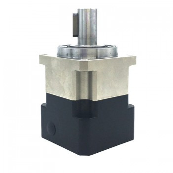
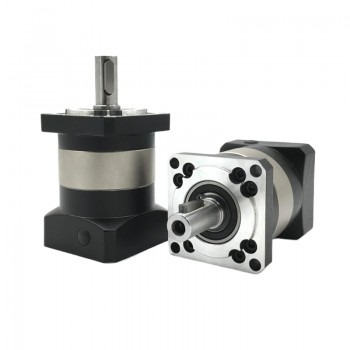
Main functions and protection measures of helical planetary gearbox
1.Main introduction of helical planetary gearbox A helical planetary gearbox is a mechanical transmission system composed of a planetary gear mechanism and helical gears. The core lies in the layout of the planetary gears. The central sun gear is surrounded by multiple planetary gears, and the outer side of the planetary gears is wrapped with an annular gear ring, and all gear axes remain parallel. The characteristic of helical gears is that the tooth shape is inclined at an angle to the axis, and the common angle range is between 15 and 30 degrees. This design makes the gear meshing process more coherent and effectively reduces the operating noise.
2.Working principle of helical planetary gearbox When the motor drives the sun gear to rotate, the planetary gear generates a reaction force during the self-rotation process, pushing the planet carrier to start rotating. The meshing method of the helical gears causes an axial component to exist at each contact point, and this force is transmitted to the output shaft through the planet carrier. Because multiple planetary gears share the load at the same time, the helical planetary gearbox has a load-bearing capacity of about 40% higher than that of the parallel shaft gearbox at the same volume, which is particularly suitable for heavy-duty equipment.
3.Main functions of helical planetary gearboxes 1. Improve transmission smoothness: The design of helical gears can effectively reduce vibration and noise, making the transmission process smoother. The helical gears have a longer tooth contact line, which can better disperse the load, reduce impact and vibration, and thus improve the smoothness of transmission.
2Strong load-bearing capacity: Helical planetary gearboxes usually have a large load-bearing capacity and can withstand high torque and load. This feature makes it excel in applications that require high torque transmission, such as heavy machinery and industrial equipment. 3. Adapt to complex working conditions: The design of helical gears enables it to adapt to complex working conditions, such as variable loads, impact loads, etc. Its excellent load-bearing capacity and transmission smoothness enable the helical planetary gearbox to maintain good performance under various working conditions. 4. Reduce friction and wear: Through precise design and manufacturing, helical planetary gearboxes can reduce friction and wear and extend service life. Its structural design allows the gears to always remain in mesh with each other, eliminating the slip phenomenon during gear shifting and reducing friction and wear. 5. Wide application: Due to its excellent performance, helical planetary gearboxes are widely used in many industries. For example, in the field of mechanical industry and automated production, its efficient and stable transmission performance has been fully utilized. Especially in the gear reducer in the electric drive axle, the helical planetary gearbox can smoothly transmit the power of the motor to the wheels, and at the same time realize flexible adjustment of the vehicle power through precision transmission.
4.Protection measures for helical planetary gearboxes 1. Regularly check and replace lubricating oil: Regularly check the oil level and quality of the lubricating oil to ensure that the oil level is within the specified range and the oil is clear and free of impurities. The lubricating oil should be replaced after the first 200-300 hours of operation of the new gearbox, and then every 12 months or 2000 hours of operation, and it should be shortened to 6 months under heavy load conditions. Choose the appropriate lubricating oil brand and model to avoid mixing lubricating oils of different brands. 2. Check the gear and bearing status: Regularly check the wear of the gears, including whether there are cracks and peeling on the tooth surface, to ensure good gear meshing. Check the lubrication status and rotation flexibility of the bearings, and clean and replace damaged bearings in time. 3. Prevent overload and impact load: Avoid long-term overload of the gearbox, and select a suitable motor to match it to meet the specified conditions of use. Prevent excessive impact load to prevent gears from breaking due to excessive load.
4.Prevent dust and impurities from entering: Keep the inside of the gearbox clean to prevent dust and impurities from entering, and avoid wear and failure caused by impurities. 5. Monitor temperature and vibration: Regularly use an infrared thermometer to detect the temperature of the gearbox housing and bearing parts to ensure that the temperature is within the normal range. Use a vibration meter to monitor the vibration of the gearbox and detect abnormal vibration and noise in time. 6. Regular maintenance: Regularly clean and replace the lubricating oil filter to ensure the normal operation of the lubrication system. Check whether the connecting bolts are loose to ensure that the connection between the reducer and the motor and load equipment is firm. 7. Deal with abnormal situations: Once abnormal temperature, excessive vibration or abnormal noise is found, the machine should be stopped for inspection immediately, and the fault should be eliminated before continuing to use.
Source:https://witty-shrimp-l6jg5w.mystrikingly.com/blog/main-functions-and-protection-measures-of-helical-planetary-gearbox
0 notes
Text
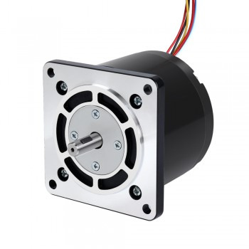
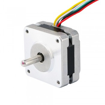
Design advantages and main applications of hollow shaft stepper motors
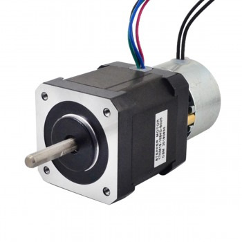
1.A brief introduction to hollow shaft stepper motors The design features of hollow shaft stepper motors allow for a hollow hole in the center of the shaft. This design optimizes mechanical design, facilitates wiring, and saves design space and production costs. According to different application requirements, hollow shaft stepper motors can be divided into two categories: designs without precision requirements and designs with precision requirements. Motors without precision requirements are mainly used for routing, light transmission, or passing through other media, while motors with precision requirements are used in occasions that meet specific precision requirements, such as using third-party lead screws or ball screws.

2.Specific structural features of hollow shaft stepper motors 1.Stator: There are multiple coils on the stator. When the current in the wire coil changes, a magnetic field is generated around it. This magnetic field generates force on the nearby coils, causing the coil to move. 2.Rotor: The rotor is a hollow structure with multiple magnetic poles inside. The hollow design of the rotor allows the motor to be easily connected to other mechanisms to achieve flexible motion control. 3.Electromagnetic induction: The working principle of the hollow shaft stepper motor is based on the law of electromagnetic induction. By controlling the number and order of the energized coils, the rotation angle and direction of the rotor can be precisely controlled.
3.Design advantages of hollow shaft stepper motors
1.Optimized mechanical design: The design of the hollow shaft stepper motor allows a hollow hole in the center of the shaft. This structure allows the axial direction to penetrate the space, thereby optimizing the mechanical design, especially in application scenarios where materials, signals or light need to be transmitted, and a more compact and optimized layout can be achieved. 2. Convenient wiring: The hollow structure is convenient for wiring, which can avoid twisting and damage of cables, especially in application scenarios where cables, wires, and sensor signals need to be transmitted. This feature is particularly important. 3. Save design space and production costs: The hollow shaft stepper motor reduces the volume and weight, reduces noise, realizes multi-purpose integration, reduces costs, and is relatively simple to manufacture and use. 4. Versatility: The hollow structure of the hollow shaft stepper motor can be installed with optical parts such as lenses and prisms to become a high-precision rotating optical device, and can also be connected to a gearbox to become a large torque output mechanism, which increases the diversity of its application scenarios. 5. High-precision control: For hollow shaft stepper motors with precision requirements, the precision of the inner hole diameter and thread is very high, which is usually used to meet the needs of using third-party trapezoidal screws or ball screws to ensure the mechanical accuracy and operating accuracy of the entire stepper screw motor.

4.Main application areas of hollow shaft stepper motors
1.In automated production lines and robot arms, hollow shaft stepper motors can accurately control the motion trajectory of the robot arm and improve operational accuracy and flexibility.For example, on automated production lines, stepper motors can accurately control the movement of the robot arm to ensure the stability and efficiency of the production process.
2.In the field of medical devices, hollow shaft stepper motors are widely used in surgical robots, rehabilitation equipment, etc., providing high-precision, smooth motion and position control. Its hollow shaft design allows the motor to dissipate heat better during surgery and is convenient for connecting to other devices.
3.In the field of optical equipment and aerospace, hollow shaft stepper motors can be used to install optical parts such as lenses and prisms through their hollow shafts, becoming high-precision rotating optical devices. In addition, its lightweight design enables weight reduction and improved overall performance when used in the aerospace field.
4.In CNC machine tools and automation equipment, hollow shaft stepper motors can accurately control the processing position and speed of workpieces to achieve high-precision processing. This type of motor also performs well in automated packaging machines, textile machinery and other equipment, providing high-efficiency motion control.
5.In the field of smart homes, hollow shaft stepper motors can be used in the control systems of smart door locks, smart curtains and other equipment to achieve automated control of equipment. Its lightweight design and low noise characteristics make these applications more convenient and reliable.
Source:https://olgana.pixnet.net/blog/post/184161811
0 notes
Text
Introduction to the main faults of variable reluctance stepper motors
1.Working principle of variable reluctance stepper motors The working principle of variable reluctance stepper motors is mainly based on electromagnetic induction and magnetic field changes. Specifically, when an electrical pulse signal is given, the corresponding coil will be energized to generate a magnetic field. This magnetic field interacts with the permanent magnet or electromagnet inside the motor to make the motor rotor rotate a step angle in a specific direction. By continuously giving multiple electrical pulse signals and controlling the sequence and time interval of these signals, continuous rotation and precise positioning of the motor can be achieved.
2.The main structure of variable reluctance stepper motors
1.The stator is a fixed part, mainly composed of a set of electromagnet windings, which is used to generate a magnetic field. The design of the stator requires extremely high stability and strength to ensure the precise control of the motor.
2.The rotor is the rotating part of the stepper motor, consisting of a set of steel materials or iron cores. When the magnetic field of the stator changes, the rotor will rotate with the change of the magnetic field.
3.The excitation system controls the current and magnetic field of the stator winding and is the commander of the motor. It is responsible for managing the sequence and power-on time of the winding current to ensure that the motor can rotate in the expected steps.
4.The control circuit is responsible for generating and controlling the current signal to ensure that the excitation system can work in the predetermined order and timing. The design and implementation of the control circuit are crucial to the performance and accuracy of the motor.
3.Control methods of variable reluctance stepper motors
1.Open-loop control: This is the most basic and simplest control method for stepper motors. In this control method, the controller sends a series of pulse signals to the driver, and each pulse causes the motor to rotate a fixed angle.
2.Closed-loop control: In order to improve the accuracy and stability of control, closed-loop control can be used. Closed-loop control monitors the position and speed of the motor in real time through a feedback mechanism, and adjusts the control signal based on the feedback results. Common closed-loop controls include position closed-loop and speed closed-loop.
3.Vector control: Vector control is an advanced control strategy that achieves efficient energy utilization and improved dynamic performance by precisely controlling the magnetic field and torque of the motor. Vector control can obtain the rotor position and current data of the motor through the magnetic encoder and phase current sampling circuit, and then achieve precise control through the closed-loop control algorithm (such as position loop, speed loop and current loop) inside the software.
4.Angle control method (APC): This method adjusts the current waveform by controlling the opening angle and the closing angle, thereby affecting the output torque and speed of the motor. The advantage of angle control is that the torque adjustment range is large and suitable for high-speed operation, but not suitable for low-speed conditions.
5.Current chopping control method (CCC): In this method, the current peak is adjusted by controlling the chopping current limit to control the torque and speed of the motor. This method is suitable for occasions where fine adjustment of motor performance is required.

4.Main faults of variable reluctance stepper motors
1.Heating problem: Variable reluctance stepper motors generate a lot of heat when running at high speed, and their heat dissipation conditions are poor, which makes the internal temperature of the motor easy to rise. If the temperature is too high, it may cause the insulation of the motor winding to burn out, thereby affecting the service life of the motor. 2. Failure of the reluctance synchronization mechanism: Since the variable reluctance stepper motor adopts a complex reluctance synchronization mechanism, there are many parts and it is difficult to process. Once a part fails, the entire mechanism may need to be disassembled and repaired, which increases the difficulty and cost of maintenance. In addition, the reluctance synchronization mechanism is also prone to wear. 3. Difficulty in starting: The variable reluctance stepper motor does not have the characteristics of self-starting, and requires external auxiliary equipment to start, which increases the difficulty and cost of motor starting. 4. Bearing problem: The bearing is an important part of the motor. Long-term operation may cause wear or damage, abnormal vibration and noise. Regular inspection and maintenance of bearings are the key to preventing such failures. 5. Electrical failure: Including low stator winding voltage, open stator winding or circuit problems, broken starter cage or poor contact at the joint. These faults may cause the motor to fail to operate or start normally. 6. Demagnetization problem: For permanent magnet synchronous motors, there is also a risk of demagnetization. Demagnetization may cause the motor to degrade in performance or even fail to work properly. Demagnetization can be determined by measuring the difficulty of the motor's rotor rotation. 7. Excessive noise and vibration: This may be caused by excessive transmission gear clearance, excessive load, incorrect wiring, etc. 8. Step loss and step failure: This may be caused by excessive load, unstable power supply voltage, drive circuit problems, etc.
0 notes
Text
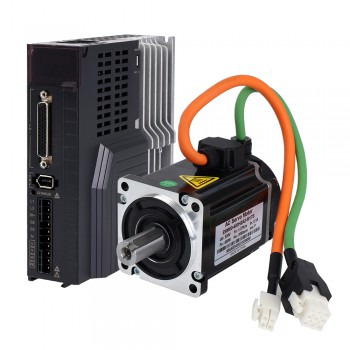
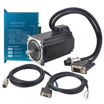
Technical features and operating precautions of integrated servo motors
1.Basic components of integrated servo motors Integrated servo motors are mainly composed of servo motor body, encoder and driver. The servo motor body is the component that performs mechanical movement. The encoder is used to feedback the position and speed information of the motor, and the driver is responsible for receiving control signals and driving the motor to operate. The control circuit is responsible for generating control signals and monitoring the operating status of the motor to ensure accurate control and stable operation of the system.

2.Working steps of integrated servo motors 1. Receiving control signals: The servo motor receives control signals from the external controller through the driver. These signals tell the servo system where to move, at what speed or direction to move. 2. Driving the motor: The driver sends power to the servo motor to drive it to rotate according to the received control signal. 3. Feedback monitoring: The encoder or other feedback device inside the servo motor measures the current position and speed of the output shaft and feeds this information back to the control circuit. 4. Adjustment control: The control circuit compares the feedback signal with the target value, adjusts the motor's current, voltage and other parameters to ensure that the motor can accurately reach and maintain the set position or speed.
3.Technical features of integrated servo motors
1.High-precision control: The integrated servo motor adopts advanced closed-loop control technology, and the encoder provides real-time feedback of the motor's position and speed information to achieve precise control. Its positioning accuracy can reach 0.001mm or even higher.
2.Fast response: The integrated servo motor has fast response capability and can reach the target position and speed in a very short time. This gives it a significant advantage in situations where high-speed and high-precision motion is required.
3.Good stability: The integrated servo motor adopts advanced control algorithms and drive technologies, which can maintain stable operating performance in various complex environments. At the same time, it has strong anti-interference ability and can effectively resist external interference and noise.
4.High flexibility: The integrated servo motor can be customized according to actual needs to meet the needs of different applications. In addition, it also supports multiple control modes, such as position control, speed control and torque control.
5.Intelligent design: The integrated servo motor usually adopts high-performance DSP to achieve precise and smooth motor control, which greatly improves the system integration and reduces the workload of wiring. Its opto-isolated differential signal input and multiple communication methods (such as CAN communication and Modbus communication) further improve the system's integration and maintainability. 6. High efficiency and energy saving: The integrated servo motor can maintain low temperature and energy consumption during operation, ensuring high efficiency and energy saving. For example, Schneider Electric's Lexium MDrive motor achieves high stability and low operating temperature through closed-loop control, thus ensuring high efficiency and energy saving.

4.Precautions for the operation of the integrated servo motor 1. Use environment: Try to use the servo motor in a clean and dust-free environment, and avoid using it in heavy oil, dusty or humid places to prevent damage to the motor. 2. Regular maintenance: Regularly check the housing, screws, bearings and other parts of the integrated servo motor to ensure that they are not damaged or loose. At the same time, keep the motor clean and dry to avoid the influence of moisture and dust. 3. Avoid overload work: During use, avoid overloading the integrated servo motor, and always observe the working condition of the motor to ensure that it operates within a safe range. 4. Avoid overheating: Regularly check whether the cooling fan of the integrated servo motor is working properly to prevent the motor from overheating. If the motor is found to be overheating, check the cause immediately and take measures. 5. Standard operation: When operating the integrated servo motor, follow the operating procedures to avoid misoperation and barbaric operation. Adjust the motor's speed, position, load and other parameters according to actual needs to ensure the stability and safety of the motor. 6. Cable protection: Ensure that the cable of the integrated servo motor is not subjected to torque or vertical load due to external bending force or its own weight, especially at the cable outlet or connection. The elbow radius of the cable should be as large as possible to avoid immersion in oil or water. 7. Parameter configuration: The parameter configuration of the integrated servo motor is directly related to its motion performance and load capacity. When configuring the parameters, select and adjust according to factors such as the motor model, specification, and application scenario to ensure that the motor operates in the best condition.
Source:https://olgana.pixnet.net/blog/post/180444976
0 notes
Text
Control and maintenance methods of CNC spindle motors
1.Introduction to CNC spindle motors CNC spindle motors, also known as electric spindles, refer to a new technology that integrates the machine tool spindle and spindle motor in the field of CNC machine tools. This design shortens the length of the machine tool main drive chain to zero, achieving "zero transmission", that is, the motor directly drives the spindle, thereby improving mechanical efficiency and precision.

2.Control methods of CNC spindle motors 1.Variable frequency speed control: This is one of the most common control methods for CNC spindle motors. By controlling the speed of the motor through the frequency converter, the spindle can be controlled steplessly. Variable frequency speed control can be divided into ordinary variable frequency drive, vector control and direct torque control. 2.Analog spindle control: FANUC CNC system uses analog voltage to control the spindle, and outputs 0~+/-10V analog voltage to control the start, stop, forward and reverse rotation and speed regulation of the spindle. The programming processing instruction is M03/M04Sxx. 3.Serial spindle control: In the FANUC 0i series CNC system, data control and information feedback are carried out between the CNC controller and the spindle servo amplifier through serial communication. Serial spindle control requires physical electrical hardware connection and spindle function configuration.
3.Structure of CNC spindle motor 1.Housingless motor: CNC spindle motors usually adopt a housingless motor design. This design allows the stator part of the motor to be placed in the housing of the spindle unit, and the rotating parts of the rotor and spindle are integrated, thereby achieving a compact structure and high-efficiency operation of the motor. 2.Bearing: Bearings are an important component of CNC spindle motors and mainly bear radial and axial forces. Common bearing types include ceramic ball bearings, hydrostatic bearings, and magnetic bearings. Ceramic ball bearings are lightweight and high-hardness, suitable for high-precision machining; hydrostatic bearings reduce wear and improve rotation accuracy by non-direct contact; magnetic bearings suspend the spindle by magnetic force to achieve high-precision and high-speed operation, but the cost is relatively high. 3.Cooling device: Since the CNC spindle motor generates a lot of heat when running at high speed, a cooling device is required to maintain a suitable working temperature. The cooling device ensures that the temperature of the spindle unit remains within a reasonable range to prevent performance degradation and damage caused by overheating. 4.Drive module: The drive module designed specifically for the spindle is responsible for accurately controlling the speed change function of the motor to ensure the stable operation of the spindle under different working conditions. 5.Sensor: The rear end of the spindle is equipped with a speed and angular displacement sensor, and the front end is designed with an inner tapered hole and end face to facilitate the installation and use of the tool.

4.Maintenance of CNC spindle motor 1.Cleaning and maintenance: Keeping the electric spindle clean is the key. Cleaning work should include cleaning of the outer surface and the inside, especially the airtight parts, which need to be cleaned regularly with detergent to ensure normal operation. In addition, cleaning of the cooling fan or air duct is also very important to ensure sufficient cooling of the spindle. 2.Lubrication maintenance: Reasonable lubrication can reduce the friction and wear of the electric spindle and extend its service life. Check the oil level and oil quality of the lubricator, change the lubricating oil regularly, and keep the lubrication system unobstructed and in good working condition. 3.Bearing inspection: The bearing is the part of the electric spindle that is most prone to failure, so bearing inspection is very necessary. Check whether the bearing has impurities, whether it is well lubricated, whether it is severely worn, etc. Once an abnormality is found, it needs to be replaced or repaired immediately to avoid safety hazards to the use of the machine tool. 4.Reasonable use: Avoid overload during use, eliminate impact loads, avoid long-term no-load work, etc., and reasonable use can effectively extend the life of the electric spindle. 5.Regular inspection: The axial runout and radial runout of the electric spindle need to be inspected regularly. For example, the axial runout of the electric spindle is generally required to be 0.002mm (2μm), and it is inspected twice a year; the radial runout of the inner cone hole is also 0.002mm (2μm), and it is inspected twice a year; the radial runout of the far end of the mandrel (250mm) is 0.012mm (12μm), and it is inspected twice a year. 6.Preventive maintenance: Perform preventive maintenance regularly based on the equipment usage and manufacturer's recommendations, such as replacing wearing parts and checking motor insulation performance. Preventive maintenance aims to prevent potential problems and ensure the normal operation of the equipment. 7.Fault maintenance: Maintenance performed when the equipment fails. This type of maintenance is usually performed after the equipment fails, with the aim of restoring the normal operation of the equipment as soon as possible.
Source:https://olgana.pixnet.net/blog/post/178552702
0 notes
Text
How to drive a unipolar stepper motor
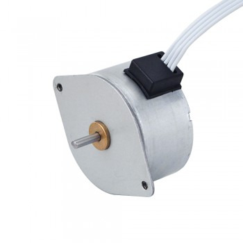
1.Introduction A unipolar stepper motor is a special stepper motor, which is characterized by achieving stepping motion through a specific driving mode. This motor usually has a permanent magnet with 5 or 6 wires and a hybrid structure. Its working principle is based on a design in which each of the two windings has a central tap. In use, the center tap of the winding is usually connected to the positive power supply, and the two ends of each winding are alternately grounded to reverse the direction of the field provided by the winding.

2.Working mode of unipolar stepper motor 1.In the single-phase driving mode, the stepper motor has only one set of windings, which is connected to an external power supply to make the magnetic field on the stator change continuously within a cycle. When the magnetic field changes, the rotor rotates with the change of the magnetic field. The advantages of this method are simple structure, easy control and implementation, but it is easy to lose step when running at low speed. 2.The two-phase drive method is different. It involves two sets of windings in the stepper motor. The windings are connected to an external power supply to make the magnetic field on the stator change alternately. Only one set of windings is energized at a time, attracting or repelling the rotor, causing the rotor to rotate clockwise or counterclockwise. Compared with the single-phase drive method, the two-phase drive method has better performance and stability, but the implementation is relatively complicated.
3.The drive method of unipolar stepper motor 1.The drive method of unipolar stepper motor mainly involves unipolar drive circuits. This drive method uses four transistors to drive the two phases of the stepper motor. The structure of the motor includes two sets of coils with center taps, and the entire motor has a total of six wires connected to the outside world. This motor is sometimes called a four-phase motor, but in fact it has only two phases, and a more accurate description should be a two-phase six-wire stepper motor. The characteristic of the unipolar drive circuit is that the current in the motor coil has only one direction, the current direction does not change. This characteristic makes the unipolar motor relatively simple to drive. 2.The driving methods of unipolar stepper motors also include the three most basic methods: single 4-beat method, double 4-beat method and single double 8-beat method. In the single 4-beat driving process, only one phase is energized at each moment, while the double 4-beat method is that two adjacent phases are energized at each moment. These two methods have their own characteristics. The former only works in one phase at a time, and the latter provides a greater output torque by driving two adjacent phases at the same time. The single double 8-beat method is a hybrid driving method that combines the single 4-beat method and the double 4-beat method. It completes a cycle through 8 steps. This method is more suitable for occasions where a greater output torque is required. In addition, the driving circuit of the two-phase unipolar stepper motor is basically the same as the driving circuit of the two-phase bipolar stepper motor in terms of input segment configuration, internal logic, control circuit and drive circuit use, but the output segment configuration is different. Two-phase bipolar stepper motors are driven using a dual-channel H-bridge, while two-phase unipolar stepper motors are driven using two switches (MOSFET) in two channels. This is because a two-phase unipolar stepper motor can be driven by making the current flow in a certain direction from the power supply supplied to the center tap of each coil.
4.Application areas of unipolar stepper motors 1.Robot control: Unipolar stepper motors are suitable for robot control operations, such as in manufacturing and assembly line control. By accurately controlling the rotation angle and step length of the stepper motor, the robot can achieve precise motion and position control to complete various tasks. 2.Medical equipment: Unipolar stepper motors are also suitable for medical equipment, such as synchronous or high-speed motion control. In medical equipment, stepper motors are used to control the movement and position of medical devices, for example, to control the rotation angle and position of X-ray equipment, and to control the joint drive system of surgical robots. 3.Automation equipment: unipolar stepper motors are suitable for automated production processes, such as fast and precise position control on conveyor belt systems, and robots that inspect and assemble parts in automobile manufacturing. 4.Joint drive systems and positioning systems in robotics: stepper motors are widely used in joint drive systems and positioning systems in robotics. By controlling the rotation angle and step length of stepper motors, precise motion and position control can be achieved to complete various tasks.
Source:https://olgana.pixnet.net/blog/post/176250202
0 notes
Text
Advantages and maintenance methods of Linear Guide Rail
1.A brief introduction to Linear Guide Rail Linear Guide Rail is a high-precision, high-rigidity, long-life linear guide device, mainly used to reduce friction and improve the efficiency of mechanical equipment. It consists of two parts: the track and the slider. By placing an appropriate amount of rolling elements (such as balls or rollers) between the track and the slider, the slider can reciprocate on the track, thereby reducing friction and wear and improving the accuracy and efficiency of mechanical equipment.

2.Components of Linear Guide Rail 1.Guide rail: The guide rail is the basic part of the linear guide and provides a track for linear motion. 2.Slider: The slider is installed on the guide rail and contacts the guide rail through the rolling element to achieve linear motion. 3.Rolling element: The rolling element can be a ball or a roller. The rolling element of the ball-type guide rail is a steel ball, while the rolling element of the roller-type guide rail is a steel column. The ball-type guide rail has low friction resistance and is suitable for light load and high-speed motion; the roller-type guide rail has a strong load-bearing capacity and is suitable for heavy load occasions. 4.Retainer: The retainer is used to fix the rolling element to prevent it from falling off. 5.Ball return groove: The ball return groove design allows the rolling element to circulate between the slider and the guide rail, ensuring the continuity and stability of the linear motion.
3.Advantages of Linear Guide Rail 1.High precision: The linear guide rail can achieve high-precision movement through precision machining and high-precision assembly, meeting the high precision requirements of modern industry. It can achieve ultra-precision machining at the micron level, making the machining quality more stable. 2.High rigidity and high speed: The linear guide rail has the characteristics of high rigidity and can withstand large shocks and vibrations, ensuring the stable operation of the equipment under dynamic conditions. In addition, the linear guide rail can withstand high-speed movement, which greatly improves production efficiency. 3.Low friction: The track surface of the linear guide rail has been specially treated with high hardness and finish, thereby reducing sliding friction, making the slider more stable when moving, and extending the service life of the guide rail. Due to its small friction coefficient and low energy consumption, the moving parts are not easy to deviate when moving, ensuring the movement accuracy. 4.Lightweight and convenient: The linear guide rail has a compact structure, small size, light weight and easy installation. Its lightweight characteristics reduce the weight and volume of moving parts, making it suitable for installation and use in various complex environments. 5.Long life and high load capacity: The linear guide rail adopts high-quality materials and advanced manufacturing processes, and has a long service life. In addition, it can withstand high loads and is suitable for heavy-duty equipment such as large CNC machine tools and heavy industrial machinery. 6.Convenient maintenance: The linear guide rail is easy to maintain in the later stage, and the guide rail is simple to replace after wear, while the hard rail requires a complex adjustment process. 7.Wide range of application fields: Due to the advantages of high precision, high rigidity and high speed of the linear guide rail, it has become an important core component in the modern manufacturing industry and the field of robotics, and is widely used in machine tools, semiconductor equipment, electronic equipment, precision machinery, automation equipment and various robots and other fields.

4.Maintenance methods of Linear Guide Rail 1.Cleaning: Regular cleaning of the linear guide rail is an important part of maintenance. The purpose of cleaning is to remove dust, dirt and metal chips from the surface of the guide rail to prevent these impurities from causing wear on the guide rail. The cleaning steps include using a clean cloth or brush to remove dirt from the surface of the guide rail, using an appropriate detergent to clean the guide rail to ensure that there is no residue, and finally wiping it with a dry cloth to avoid moisture residue. 2.Lubrication: Proper lubrication can reduce friction, reduce temperature and extend service life. The lubrication steps include selecting a suitable lubricant (oil or grease) according to the user manual, regularly checking the lubrication status to ensure that the lubricant is sufficient, and evenly applying lubricant to the contact surface of the guide rail and the slider to ensure that the entire contact surface is covered. 3.Inspection: Regularly checking the status of the linear guide rail can detect potential problems in time. The inspection content includes the parallelism and straightness of the guide rail to ensure that it meets the technical requirements; checking whether the slider moves smoothly and whether there is any jamming; checking whether the sealing device is intact to prevent dust and impurities from entering. 4.Adjustment: During use, the linear guide rail may become loose or offset. Regular adjustment can ensure the normal operation of the guide rail. The adjustment steps include adjusting the installation position of the guide rail according to the requirements of the equipment to ensure its parallelism and centering; checking and tightening the fixing screws of the guide rail to ensure its firmness. 5.Replacement: When the linear guide rail is severely worn or damaged, it needs to be replaced in time. The replacement steps include stopping the machine and disconnecting the power supply to ensure safety; removing the damaged guide rail and slider, cleaning the installation position; installing a new linear guide rail and ensuring its correct installation position.
Source:https://olgana.pixnet.net/blog/post/172510558
0 notes
Text
Conditions for the smooth operation of servo motors
1.Definition of servo motors A servo motor is a motor that controls the operation of mechanical elements in a servo system and has high-precision position control capabilities. It can convert the input voltage signal into angular displacement or angular velocity output on the motor shaft, thereby driving the control object.
2.Classification of servo motors Servo motors are mainly divided into two categories: DC servo motors and AC servo motors. DC servo motors are powered by DC power supplies, have good speed regulation performance and high torque output capabilities, and are suitable for application scenarios that require precise control. AC servo motors are powered by AC power supplies, have high power density and good dynamic response capabilities, and are suitable for high-speed and high-precision control systems.
3.Technical features of servo motors 1.High precision: The servo motor uses advanced closed-loop control technology to monitor the position and speed information of the motor in real time through the built-in encoder to achieve high-precision position control. Its positioning accuracy can reach 0.001mm or even higher. 2.Fast response: The servo motor responds quickly to the control signal and can reach the target position and speed in a very short time, adapting to high-speed and high-precision motion occasions. 3.Good stability: The servo motor adopts advanced control algorithms and drive technology, which can maintain stable operating performance in various complex environments and has strong anti-interference ability. 4.High flexibility: The servo motor supports multiple control modes, such as position control, speed control and torque control, etc., and can be customized according to actual needs to meet the needs of different applications. 5.Closed-loop control: The servo motor monitors the operating status of the motor in real time through the built-in encoder or other feedback device, and feeds back the information to the control system to form a closed-loop control, thereby improving the control accuracy and stability. 6.High reliability: The servo motor has a self-protection mechanism, which can effectively prevent motor overload, overheating and other faults, and improve the reliability and safety of system operation. 7.Energy saving and high efficiency: The servo motor can automatically adjust the power output according to the load conditions, effectively reduce unnecessary energy consumption, and has a high energy efficiency ratio. 8.Strong adaptability: The servo motor can bear large load fluctuations, which is very suitable for occasions with instantaneous load changes and fast operation requirements.
4.Conditions for smooth operation of servo motors 1.Power supply stability: Servo motors require a stable power supply to ensure their normal operation. The power supply capacity should be slightly larger than the actual capacity required by the motor to ensure that the motor can operate stably. In addition, the stability of the power supply voltage is also very important, and the power supply wiring should be reliable to avoid problems such as poor contact. At the same time, the ground connection method of the power supply should also be correct to ensure safety. 2.Encoder status: The encoder is the core component of the servo motor to ensure accuracy and control. There are many types of encoders, such as absolute encoders and incremental encoders. When selecting an encoder, factors such as accuracy, speed, working environment and cost need to be considered. Damage or failure of the encoder will cause inaccurate control of the servo motor, so the encoder needs to be kept in good condition. 3.Controller selection: The controller of the servo motor is one of the key components. The controller can control parameters such as the speed and torque of the servo motor. When selecting a controller, it is necessary to select it according to the needs of the specific scenario, such as motion controller, PLC controller, PC controller, etc. At the same time, the interface and communication protocol of the controller need to be considered to ensure good interface and communication with other devices. 4.Load matching: The load of the servo motor directly affects its operation effect. The load should match the operating parameters of the motor. Excessive load will affect the speed and torque of the motor, while too small load will reduce the control accuracy of the motor. When installing the load, you also need to pay attention to its fixed position and operating environment to avoid interference with the operation of the motor due to loosening or rotation of the load. 5.Operating environment: The servo motor should be operated in a dry, temperature-appropriate, well-ventilated and well-lit environment. Avoid contact between the motor and liquids such as water and other harmful substances. Clean and maintain the motor regularly to ensure its good operating condition. 6.Impact of the working environment: Ambient temperature, humidity and corrosive environment will affect the power and operating stability of the servo motor. High temperature will increase the temperature of the motor windings and internal components, resulting in increased copper and iron losses, which may cause the motor to automatically reduce the output power. Low temperature environment may increase the viscosity of the lubricating oil, resulting in increased mechanical friction. High humidity environment may cause condensation inside the motor or at the terminals, increasing the risk of aging or short circuit of the insulation layer. Corrosive environment may corrode the motor housing, wiring parts and other exposed components, affecting the output power of the motor.
Source:https://olgana.pixnet.net/blog/post/169560178
0 notes
Text
Design features and selection principles of linear stepper motors
1.Working principle of linear stepper motors The working principle of linear stepper motors is to drive the slider to move along a straight line through an electromagnetic field. Its basic structure includes a stator and a mover. The stator is usually composed of two electromagnets, and the mover is composed of a slider with a permanent magnet. The working principle is to generate an alternating magnetic field by alternately exciting the electromagnets, which pushes the slider to move along a straight line. When one electromagnet is activated, it generates a magnetic field that attracts the slider and moves toward it; when the other electromagnet is activated, it generates an opposite magnetic field that pushes the slider to move in the opposite direction. By alternately activating these two electromagnets, the slider can reciprocate along a straight line.

2.Common application areas of linear stepper motors 1.Industrial automation: Linear stepper motors are widely used in industrial robots, mold machinery, printing machinery and other equipment, and can provide high-precision, high-stability and high-efficiency motion control. 2.Planar mobile devices: Linear stepper motors are often used in planar mobile devices such as laser cutting machines, printers, scanners, etc., and achieve high-quality processing and printing effects by precisely controlling the movement of the motor. 3.Measuring instruments: In high-precision 3D scanners, optical measuring equipment and other measuring instruments, linear stepper motors are used for precise measurement and positioning to ensure the accuracy of measurement. 4.Medical equipment: Linear stepper motors are widely used in medical equipment such as medical instruments and surgical instruments to drive the movement of scanning frames to ensure accurate imaging of medical imaging equipment. 5.Other applications: Linear stepper motors can also be used in scenes such as focusing of camera lenses and moving optical equipment to provide high-precision position control.
3.Design features of linear stepper motors 1.High precision: Linear stepper motors adopt a direct drive structure, with no backlash and high structural rigidity. The accuracy of the system mainly depends on the position detection element, which can reach the submicron level through a suitable feedback device. 2.No mechanical contact wear: There is no mechanical contact wear between the stator and the mover of the linear stepper motor. The system motion contact is borne by the linear guide rail, with fewer transmission parts, smooth operation, low noise, simple structure, simple maintenance, or even maintenance-free, high reliability and long service life. 3.Modular structure: The stator of the linear stepper motor adopts a modular structure, and the running stroke is theoretically unlimited. 4.Wide operating speed range: The speed range of the linear stepper motor is from a few microns to several meters per second, which can meet different application requirements. 5.High acceleration and speed: In practical applications, the linear stepper motor has achieved an acceleration of 5.5g and a speed of 2.5m/s. 6.High efficiency: Since there is no intermediate transmission link, the energy loss during mechanical friction is eliminated, and the efficiency is high. 7.Fast response speed: Since some mechanical transmission parts with large response time constants, such as lead screws, are eliminated, the dynamic response performance of the entire closed-loop control system is greatly improved, and the response is extremely sensitive and fast. 8.Wide application: Linear stepper motors are mainly used in automatic control systems, long-term continuous operation drive motors, and devices that need to provide huge linear motion energy in a short time.

4.Selection principles of linear stepper motors 1.Load characteristics: Select a suitable motor according to the rotational inertia and friction load of the load. Loads with large moment of inertia should use motors with large frame sizes, while friction loads need to consider static torque, which is usually 2-3 times the friction load. 2.Speed and step angle: The step angle of the stepper motor should be selected according to the load accuracy requirements, and the step angle should be equal to or less than the resolution required by the load. For example, if the positioning accuracy of the load is ±0.5°, the angle rotated by one pulse of the motor should be less than 0.5°. 3.Current parameters: Motors with the same static torque have very different operating characteristics due to different current parameters. The current of the motor can be judged by the torque-frequency characteristic curve. 4.Working environment: Select a suitable stepper motor according to the use environment. For example, for special environments that require waterproofing and oil resistance, special stepper motors should be selected. 5.Application scenarios: Linear stepper motors are generally used in low-speed situations, with a speed not exceeding 1000 revolutions per minute. It is best to control the speed between 1000-3000PPS (0.9 degrees). Appropriate deceleration devices can improve work efficiency and reduce noise.
0 notes
Text
How to improve the accuracy of closed-loop stepper motors
1.What is the role of closed-loop stepper motors The role of closed-loop stepper motors mainly includes high-precision position and speed control, improving the response speed and acceleration performance of the system, enhancing the load capacity and efficiency of the system, and achieving low-noise and low-vibration operation. Closed-loop stepper motors achieve high-precision position and speed control by introducing position feedback and speed feedback, which significantly improves the control accuracy and stability of the entire system. This feedback mechanism enables the closed-loop stepper motor to respond to operating instructions more quickly, thereby improving the response speed and acceleration performance of the system. In addition, by better controlling the speed and acceleration of the motor, the closed-loop stepper motor enhances the load capacity of the system and improves the efficiency of the system. Finally, due to the ability to better control the operation of the motor, the closed-loop stepper motor achieves low-noise and low-vibration operation, thereby improving the reliability and stability of the entire system.
2.Working principle of closed-loop stepper motors The closed-loop stepper motor is an intelligent drive device that is widely used in the fields of machinery, automation, and electronic equipment. Its working principle is based on magnetic field interaction and current application. Specifically, when the external driver sends a control signal to the motor, the motor changes the current according to the signal to achieve rotation. At the same time, the encoder inside the closed-loop stepper motor monitors the position of the rotor in real time and feeds this information back to the control system. The control system precisely controls and positions the motor based on the information provided by the encoder, thereby achieving high-precision motion control. This closed-loop control method enables closed-loop stepper motors to have the advantages of high precision, high speed, and high reliability, and can accurately control the position and speed of the rotor, thereby achieving high-precision positioning and motion control. Compared with traditional open-loop stepper motors, closed-loop stepper motors achieve more accurate position feedback and control system adjustment through internal encoders, providing higher positioning accuracy and more reliable performance.
3.Precautions for using closed-loop stepper motors 1.Correctly connect the line sequence of the encoder and the stepper motor. Make sure that the line sequence of A+, A-, B+, and B- is correctly connected to avoid the "Phase Line Error!" error. If this error occurs, the line sequence of the motor should be readjusted after power off. 2.Keep the drive well ventilated. The drive of the stepper motor is not sealed, so care should be taken to ensure good ventilation during use to avoid overheating damage caused by long-term operation. 3.Prevent metal shavings and dust from falling into the driver. Since the driver board of the stepper motor is not sealed, metal shavings and dust should be prevented from falling into it during use to prevent short circuits and motor damage. 4.Pay attention to the positive and negative connections of the power supply. When plugging in the power supply, be sure to pay attention to the correct connection of the positive and negative labels to avoid burning the driver due to incorrect positive and negative connections. 5.Connect the basic system step by step. When connecting the circuit of the stepper motor, do not connect all the circuits at the beginning. You should gradually connect them into the most basic system, and then gradually increase the connection after confirming that it is running well. 6.Observe the state of the motor. Within half an hour of starting to run, you should closely observe the state of the stepper motor, such as whether the movement is normal, the sound and the temperature rise. If you find any problems, you should stop and adjust them immediately.
4.Ways to improve the accuracy of closed-loop stepper motors 1.Hardware connection and encoder installation: By installing an encoder, the stepper motor can achieve full closed-loop control and improve positioning accuracy. The use of encoders can be based on the segmentation requirements, with different levels of resolution, for real-time feedback, thereby achieving precise control of the stepper motor. 2.Origin control: According to the Z signal of the encoder, the coordinate origin is identified and calculated. In this way, the accuracy can reach a certain standard, ensuring that the stepper motor can accurately return to or locate to the specified origin position. 3.Out-of-step control: According to the feedback data of the encoder, the output pulse is adjusted in real time, and corresponding out-of-step adjustment measures are taken to ensure the stable operation and precise position control of the stepper motor. 4.Optimized current control method: Through PWM control and current attenuation mode, the step error problem under low-speed operation or positioning control, as well as the torque instability problem under high-speed operation, are solved, thereby improving the operation quality and positioning accuracy of the stepper motor. 5.Reduce the step angle and increase the number of beats: The accuracy of the stepper motor can be increased by reducing the step angle or increasing the number of beats. When the double beat system is adopted, the step angle is reduced by half, thereby improving the working accuracy. 6.Increase the number of rotor teeth: Increasing the number of rotor teeth can also reduce the step angle, thereby reducing the error of motor operation and improving positioning accuracy.
Source:https://olgana.pixnet.net/blog/post/163203529
0 notes
Text
Technical requirements for the design of brake stepper motors
1.Function of brake stepper motors The main function of brake stepper motors is to provide sufficient static locking torque for the drive motor shaft in the vertical motion mechanism to prevent the motor shaft without brake from being in a non-locked free state when the system is accidentally powered off, and the load falls due to gravity. The brake stepper motor is equipped with a brake device (brake device) at the tail of the stepper motor, and when the motor is powered off, the brake is released and tightly holds the motor shaft, thereby achieving power-off self-locking. This design is particularly suitable for vertical motion transmission. When the stepper motor is powered off, the brake can be activated instantly to fix the motor shaft, solving the problem that the motor can still maintain a locked state when the stepper motor is powered off.

2.Components of brake stepper motors 1.Stepper motor: This is the core part of the brake stepper motor, responsible for converting electrical pulse signals into mechanical motion. Stepper motors are usually composed of stators, rotors, coils and drivers. 2.Brake: The brake is one of the key components of the brake stepper motor. It is used to brake the motor immediately when the power is off or the emergency stop occurs to prevent the mechanism from sliding down due to gravity. Common types of brakes include electromagnetic brakes, spring brakes, etc. 3.Controller: The controller is used to receive instructions from the host computer and convert them into motor movements. It can achieve precise control of the stepper motor, including the control of parameters such as speed, position, acceleration, etc. 4.Power supply: Provide a stable power supply for the stepper motor and brake to ensure the normal operation of the motor and brake. 5.Sensor: Used to feedback the actual motion state of the motor, such as position, speed and other information. This information can be used for closed-loop control to improve control accuracy and stability. 6.Mechanical structure: Including mechanical components such as motor seat, bearings, couplings, etc., used to support and connect various components to ensure the stable operation of the entire system.
3.Technical requirements for brake stepper motors 1.Environmental adaptability: The brake stepper motor should be able to work normally at an ambient temperature of -15℃ to +40℃, and the friction plate surface must be oil-free. In addition, the relative humidity of the air should not exceed 90%, and there should be no condensation. 2.Material and style: During the design and production process, attention should be paid to the rationality of the material and style to ensure the excellence of the motor in quality and effect. This includes selecting appropriate materials and designs to ensure the performance and durability of the motor. 3.Insulation level and protection level: The insulation level of the motor is usually Class B and the protection level is IP23. This means that the motor has a certain degree of dust and water resistance and is suitable for use in general industrial environments. 4.Power supply requirements: The power supply frequency should be 50Hz±5%, and the power supply voltage fluctuation range is +10% to -18%. This ensures that the motor can still work stably under different voltage conditions. 5.Air gap requirements: The air gap for normal operation needs to be guaranteed and cannot exceed the maximum air gap requirements. This helps to ensure the efficiency and performance of the motor. 6.Electromagnetic air gap: The brake stepper motor forms an air gap electromagnetically, which is suitable for areas that require deceleration or restricted stay in a short time. All brakes must be connected to a DC24V voltage to form an air gap and operate under harsh environmental conditions. 7.Application fields: Brake stepper motors are widely used in robots, medical devices, semiconductor equipment, packaging machinery, textile machinery, CNC machine tools and other fields, which require the motor to have high precision, high reliability, low noise and other characteristics.

4.Maintenance and maintenance methods of brake stepper motors 1.Appearance cleaning: Regularly check and clean the dust and stains on the surface of the stepper motor, and keep the appearance of the motor clean to ensure that the motor can run well. 2.Fan inspection: Check the working status of the fan inside the stepper motor to ensure its normal operation. If the fan is found to be rotating abnormally, it should be handled in time to avoid overheating of the motor due to fan problems. Vibration and coupling inspection: During operation, pay attention to check whether there is abnormal vibration or noise. At the same time, check whether the connection of the coupling is firm and reliable to avoid failures during operation. 3.Temperature monitoring: When the stepper motor is running, pay attention to monitor whether its temperature is within the normal range. Excessive temperatures may affect the performance and life of the motor. 4.Internal cleaning: If the stepper motor accumulates dust after long-term use, internal cleaning is required. This usually involves disassembling the motor and performing a detailed cleaning job, including wiping the inside and outside of the motor with an appropriate detergent. 5.Replacement of parts: Regularly check the parts inside the motor, such as the timing belt, gears, and controller, and replace them in time if they are worn or damaged. Original parts should be used to ensure compatibility and performance.
6.Lubrication: Lubricate the stepper motor regularly, especially before reinstalling after cleaning or when replacing components regularly. For high-temperature parts, a suitable high-temperature lubricant should be used.
7.Storage maintenance: If the stepper motor is not used for a long time, special maintenance should be performed. This includes disassembling the motor, cleaning the inside, applying protective oil, and storing the motor in a dry and cool environment.
0 notes
Text
Permanent magnet stepper motor maintenance and maintenance methods
1.Brief introduction of permanent magnet stepper motor Permanent magnet stepper motor is a type of motor whose working principle is based on the interaction between permanent magnets and electromagnetic coils. This motor usually consists of a permanent magnet rotor and several stators, in which a group of permanent magnets are fixed on the permanent magnet rotor, and several electromagnetic coils are distributed on the stator. The constant magnetic field generated by the permanent magnet interacts with the temporary magnetic field generated by the current passing through the stator electromagnetic coil, resulting in the occurrence of a rotating magnetic field. By changing the excitation sequence and current direction of the electromagnetic coils on the stator, the steering and stepping motion of the rotating magnetic field can be achieved. Each time the excitation state of the electromagnetic coil is changed, the permanent magnet rotor will rotate a fixed angle, which is called the step angle. In order to achieve stepping motion, the permanent magnet stepper motor usually needs to control the direction and size of the current through the control circuit and driver.

2.Methods to improve the efficiency of permanent magnet stepper motors 1.Optimize electromagnetic design : Select the appropriate magnetic circuit structure, stator winding form and magnetic field distribution to achieve the best effect. At the same time, consider factors such as the magnetic energy loss and copper loss of the motor to make reasonable comprehensive optimization. 2.Optimize mechanical design: In mechanical design, factors such as rotor structure, bearings, vibration reduction, etc. should be considered to reduce mechanical loss and friction loss. 3.Optimize control strategy: Use efficient control algorithms such as vector control and direct torque control to reduce rotor loss and copper loss. 4.Optimize material selection: Select materials with high magnetic permeability and low hysteresis loss to reduce magnetic energy loss and copper loss. 5.Reduce motor loss: When the stepper motor is enabled, if the motor stops running, its shaft retention does not require full circuit operation under most working conditions. Therefore, the power consumption can be reduced by turning on the half-current function of the stepper driver. Specifically, when the motor is in a stopped state, the driver automatically switches to a half-current state, reducing the current in the winding, thereby reducing power consumption. 6.Use direct-drive permanent magnet stepper motors: Avoid using mechanical transmission mechanisms such as worm gear reducers to improve equipment efficiency. Direct-drive permanent magnet stepper motors can provide higher energy efficiency.
3.Control methods of permanent magnet stepper motors 1.Pulse control: This is a traditional stepper motor position and speed control method, in which the rotation distance depends on the number of pulses and the speed depends on the pulse frequency. Common pulse control methods include: Pulse direction type: When the pulse input jumps from high to low (falling edge), the direction input is low (or floating), and the motor rotates one step in the clockwise direction; when the direction input is high, the motor rotates one step in the counterclockwise direction. The direction definition can be configured by software. CW/CCW pulse type: When the CW pulse input jumps from high to low (falling edge), the motor rotates one step in the clockwise direction; when the CCW pulse input jumps from high to low (falling edge), the motor rotates one step in the counterclockwise direction. The direction definition can also be configured by software. A/B orthogonal pulse type: The motor rotates according to the signal fed back to the driver from a dual-channel incremental master encoder. The direction is determined by which channel leads the other channel. 2.Analog control: Stepper drives support speed control and position control based on analog signals, and stepper servos also support torque mode based on analog signal control. 3.Fieldbus control: Supports various industrial fieldbuses, including RS-485, Modbus, CAN, Ethernet, and EtherCAT. 4.Program resident mode: Complete complex single-axis motion control by executing stored programs.
4.Maintenance and care of permanent magnet stepper motors 1.Regular maintenance: Maintain the daily maintenance of permanent magnet motors to keep them in a relatively new state. This includes regular replacement of electronic components, cleaning of the machine surface, and prevention of scratches. When operating the machine, use it according to regulations, do not overload it, perform regular maintenance after use, and remove part of the machine for storage if it is not used for a long time to avoid various loose phenomena and related failures of the machine. 2.Environmental adaptability: Ensure that the stepper motor works in a dry, well-ventilated environment without corrosive gas and dust pollution. Avoid installing the motor in an environment that is too humid, has corrosive gases, has severe dust, and has high or low temperatures. Special cases require consultation with the manufacturer. 3.Cleaning and lubrication: After the stepper motor has been operated for a period of time, it will be stained with dust, oil and other debris, affecting normal operation. The surface of the machine should be wiped and the oil should be washed away, and lubrication should be regularly filled with oil to maintain the speed and stability of operation. Install a cover to prevent dust from entering and damaging the internal parts of the motor. 4.Temperature control: Excessive temperature of the stepper motor will cause the magnetic material to demagnetize, thereby reducing the torque or even losing steps. Therefore, the surface temperature of the motor should be controlled within the allowable range. Generally speaking, the demagnetization point of magnetic materials is above 130 degrees Celsius, and some are even as high as 200 degrees Celsius, so it is completely normal for the surface temperature of the stepper motor to be 80-90 degrees Celsius. 5.Installation and adjustment: Check the appearance of the motor before installation and replace damaged parts. Keep the axial direction without obvious deviation during installation, and adjust it when necessary. After disassembly, clean, derust and oil it to ensure that the machine base accuracy meets the requirements. 6.Power supply and wiring: Connect correctly according to the drawings or instructions, and do not arbitrarily modify, disassemble or change the motor working voltage. Check whether the power supply voltage meets the rated voltage of the motor, ensure that the power supply is grounded reliably, and the wires are laid neatly to avoid crossing unnecessary wires. Through the above measures, the service life of the permanent magnet stepper motor can be effectively extended, the cost of maintenance and replacement can be reduced, and the accuracy and stability of the machine can be guaranteed to meet the needs of various application scenarios.
0 notes
Text
Precautions for using brake stepper motors
1.Definition of brake stepper motors The brake stepper motor is a special type of motor that is equipped with an encoder, a reducer and a brake device on the basis of a stepper motor. The main feature of this motor is that when the power is off, the brake device tightly holds the motor shaft to achieve the locking function of the motor in the power-on or power-off state. The design and application of brake stepper motors are intended to improve the application range, performance, etc. of the motor, while ensuring that the motor can be accurately stopped and positioned when needed.
2.Operation process of brake stepper motors 1.Normal operation: When the stepper motor is powered on, the brake device (brake device) is also powered on, and the brake device is disengaged from the output shaft of the stepper motor, allowing the motor to operate normally. This is the basic working state of the stepper motor, in which the current passes through the coil of the motor to generate a magnetic field, causing the rotor to start rotating. 2.Braking operation: When the motor needs to be stopped, the brake device is activated. This can be achieved electromagnetically, by applying an electromagnetic field to cause the rotor to be subjected to magnetic resistance, thereby slowing down or stopping the rotation. In addition, the mechanical braking method will also be activated at this time to stop the movement of the motor through physical contact. Electronic braking reduces the speed of the motor by changing the direction of the current or adjusting the voltage. 3.Release the brake: When the motor needs to run again, the brake device is released, allowing the motor to rotate freely again. This is usually achieved by powering off. When the stepper motor is powered off, the brake device is released, tightly holding the motor shaft, playing the role of fixing the motor shaft and ensuring that the motor can restart when needed.
3.Development direction of brake stepper motors 1.Technological innovation: Technological innovation is an important driving force for the development of brake stepper motors. With the advancement of science and technology, the control accuracy, response speed, and energy efficiency of brake stepper motors will continue to improve. For example, the performance of brake stepper motors can be further improved by optimizing motor structure, improving control algorithms, and introducing new materials. 2.Energy saving and environmental protection: With the enhancement of global environmental awareness, energy saving and environmental protection have become important development directions in all walks of life. As an important member of the motor field, brake stepper motors also need to continuously reduce energy consumption and reduce pollution. Energy saving and environmental protection of brake stepper motors can be achieved by adopting more efficient motor design, optimizing drive systems, and improving energy utilization. 3.Intelligence: With the rapid development of technologies such as the Internet of Things and artificial intelligence, brake stepper motors will also develop in the direction of intelligence. By integrating intelligent components such as sensors and controllers, the brake stepper motor can realize remote monitoring, fault diagnosis, automatic adjustment and other functions, thereby improving the reliability and maintenance efficiency of the equipment. 4.Multi-field application: Brake stepper motors have been widely used in many fields such as industrial automation, aerospace, and medical equipment. In the future, with the continuous advancement of technology and the expansion of application fields, brake stepper motors will play an important role in more fields. For example, in emerging fields such as new energy vehicles and smart homes, brake stepper motors will also have broad application prospects. 5.High quality and low price: With the intensification of market competition and the improvement of users' quality requirements, high-quality and low-priced brake stepper motors will become the mainstream of the market. Through large-scale standardized production and optimized supply chain management, production costs can be reduced, product quality can be improved, and market demand can be met.
4.Precautions for using brake stepper motors 1.Installation precautions: During the installation process, avoid applying excessive force to the brake stepper motor, such as knocking, dropping or excessive force, so as not to cause deformation or damage to the brake. Make sure the shaft end is aligned to the best state to avoid vibration or bearing damage. The mounting screws should be fixed with thread-specific glue, and be careful not to apply glue to the rotor surface and square wheel surface. 2.Use environment: The brake stepper motor should not be used in water or oil-invaded environments. Although it can be used in places that may be invaded by water or oil drops, it is not fully waterproof or oil-proof. The operating voltage should be controlled within the range of ±10% of the rated voltage and require smooth and interference-free. Make sure the motor driver is well ventilated to avoid damage to the motor due to excessive temperature rise. 3.Cables and lead wires: Do not stretch or bend the cables and lead wires too hard to avoid damage that causes the motor to fail to work. The cable should not be immersed in oil or water to prevent short circuits or damage. 4.Load and speed control: Ensure that the radial and axial loads applied to the motor are controlled within the specified values, and the continuous load torque should not exceed 30% of the motor stall torque to avoid affecting the motor performance. If high-speed operation is required, the speed and frequency should be gradually increased to ensure that the motor does not lose step, the noise is low and the accuracy is high. 5.Safety precautions: The brake must be opened when the motor is rotating, and it cannot be forced to drag with the brake to avoid damaging the brake in a short time. When using, be careful to avoid metal chips and dust falling into the driver board to avoid circuit short circuit.
0 notes
Text
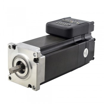
Control method of integrated stepper motor
1.What is an integrated stepper motor An integrated stepper motor is a motor that integrates the driver and motor into one. It integrates the control circuit and the motor body through a fully digital control method, and controls the movement of the motor through digital signals. The working principle of this motor is similar to that of a traditional stepper motor, both of which achieve rotation by controlling the magnetic field of the motor. Specifically, the controller of the integrated stepper motor sends a series of pulse signals to the motor, and the frequency and number of these signals determine the speed and rotation direction of the motor.
2.Control method of integrated stepper motor 1.Inductive switch control: Use inductive switches (such as magnetic switches, proximity switches, photoelectric switches, etc.) to control the origin, positioning, limit and other actions of the stepper motor. The selection of inductive switches should be based on actual needs, considering factors such as installation location, detection distance, size and accuracy. 2.Pulse control: Control the position and speed of the stepper motor by sending pulse signals. The direction and frequency of the pulse determine the rotation distance and speed of the motor. Common pulse control methods include pulse direction type, CW/CCW pulse type and A/B orthogonal pulse type. The direction definition can be configured by software. 3.Analog control: Stepper drives support speed control and position control based on analog signals, and stepper servos also support torque mode based on analog signal control. 4.Fieldbus control: Stepper drives support various industrial fieldbuses, such as RS-485, Modbus, CAN, Ethernet and EtherCAT, which are easy to integrate into automation systems. Program resident mode: It completes complex single-axis motion control by executing stored programs, which is suitable for application scenarios that require precise control.
3.Advantages of integrated stepper motors 1.Precise control and high efficiency and energy saving: Integrated stepper motors have the characteristics of precise control and accurate positioning. They are widely used in industrial automation, medical equipment, smart homes and other fields, and are favored for their high efficiency and energy saving. 2.Easy implementation and reduced wiring complexity: The design of the integrated motor and drive unit makes the system implementation easier, while reducing the complexity of wiring, speeding up the system setup and construction, and ensuring the compatibility of the motor drive. In addition, there are integrated units with integrated system-on-chip (SoC) to choose from. 3.High efficiency and reliability: The integrated stepper motor adopts advanced power electronics technology and microprocessors to achieve high efficiency and control accuracy, and has highly stable performance. Its integrated structure makes the motor more durable and easy to repair even if a failure occurs, thus reducing downtime. 4.Smaller size and reduced cost: Since the motor components are integrated into a compact frame, the integrated stepper motor is smaller in size, and the cost is greatly reduced due to the elimination of complex transmission systems and drive components. This type of motor can use smaller and lighter components at the same power, reducing production and maintenance costs. 5.Reduce noise: The integrated stepper motor makes almost no noise when running, and the noise level is also lower than that of traditional motors, providing a quieter operating environment.

4.Maintenance methods of integrated stepper motors 1.Regular inspection: Check the oil level in the oil tank, the water level in the cooling water tank, and the ventilation status of the heat sink to ensure the integrity of the conveyor belt without looseness and slippage. Check the wear and lubrication status of each component, clean dust and dirt in time, and keep the motor and its components clean. 2.Cleaning: Motors that have been used for a long time should be cleaned regularly. Disassemble the motor and wipe the internal and external dirt with edible vinegar or gasoline. In particular, when solving the problem of forward and reverse rotation or uneven speed, it is necessary to disassemble the gears and wipe them with detergent. 3.Lubrication: Stepper motors will produce part wear and heat accumulation during operation, so regular lubrication is essential. Lubricate before reinstalling after cleaning or when replacing components regularly. It is recommended to use high-temperature lubricating oil for high-temperature parts. 4.Storage issues: If the stepper motor is not used for a long time, it needs special maintenance. Disassemble the motor and clean the inside, lightly apply protective oil, and store it in a dry and cool environment. When it is not used for a long time, it is best to turn the motor every once in a while to ensure its flexibility.
1 note
·
View note