#IGBT manufacturers
Text
https://www.futureelectronics.com/p/semiconductors--discretes--transistors--bipolar-transistors/pmbta45-215-nexperia-9009695
Explore Bipolar (BJT) Transistors, Darlington Transistors, Digital Transistors
PMBTA45 Series 500 V 0.15 A 300 mW NPN SMT Small Signal Transistor - SOT-23
#Nexperia#PMBTA45#215#Transistors#Bipolar (BJT) Transistors#BJT bipolar junction transistors#IGBT transistors#Explore#Darlington Transistors#Digital Transistors#junction field effect transistor manufacturers#General Purpose
1 note
·
View note
Text
IGBT Rectifier Supplier & Manufacturer – SG Power
SG Power, a leading IGBT Rectifier supplier in India, offers lightweight, affordable rectifiers crafted by professionals using cutting-edge technology. These rectifiers excel in continuous operation without overheating. Contact SG Power the renowned brand for all grounding tools and accessories.

Visit: https://www.sgpower.co.in/igbt-rectifier.html
0 notes
Text
Top Brushless DC (BLDC) Motor Controller Wholesale Distributor in India | Millennium Semiconductors India
Millennium Semiconductors India is a wholesale distributor of BLDC Motors for various applications with technical excellence & reliability. We are leading bldc motor controller exporters in India. Visit our official website: www.millenniumsemi.com for more info.
#igbt power modules#bldc controller#bldc motor controller manufacturers#bldc motor controller#bldc motor controller india
0 notes
Text
A.B. ENTERPRISES - We are manufacturer in Electroplating Rectifier, Induction Hardening, Fly Wheel Ring, PLC Based Vertical, Fly Wheel ring Shrink etc… Any query please contact us [email protected], +91-9891964848. Bhakti Industrial Area, Bhakri Pali Road N.I.T. Faridabad, Haryana-121001.
#IGBT Based Electroplating Rectifier#Electroplating Rectifier Manufactures In Faridabad#Electroplating Rectifier Manufactures In Faridabad Haryana#Electroplating Rectifier Manufactures In Ballabgarh#Electroplating Rectifier Manufactures In Delhi#Electroplating Rectifier Manufactures In Delhi NCR#Electroplating Rectifier Manufactures In Noida#Electroplating Rectifier Manufactures In Badarpur Border#Electroplating Rectifier Manufactures In Bangalore#Electroplating Rectifier Manufactures In Karnataka#Electroplating Rectifier Manufactures In Jaipur#Electroplating Rectifier Manufactures In Gujarat#Electroplating Rectifier Manufactures In Rajkot#Double Station Hammer Manufactures In Ghaziabad#Electroplating Rectifier Manufactures In Ludhiana#Double Station Hammer Manufactures In Manesar#Gurugram#Double Station Hammer Manufactures In Faridabad Haryana#Fully Auto CI Ring Heating Machine#Fly Wheel ring Shrink Machine#ABE-25 AB Annealing#Machine Manufacturer in delhi#ABE-25 AB Annealing Machine Manufacturer#ABE-40 ABC Double Station Induction Hardening Machine#Manufacturer#Chisels Hardening Machine Manufacturer#Agriculture Tools Hardening Machine Manufacturer#Claw Hammer Hardening Machine Manufacturer#Carpenter Tools Brazing Machine#Macnufacturer
0 notes
Note
Sydney Trains M set
Class of electric train operating in Sydney, Australia
The Sydney Trains M sets, also referred to as the Millennium trains, are a class of electric multiple units that operate on the Sydney Trains network. Built by EDi Rail between 2002 and 2005, the first sets initially entered service under the CityRail brand on 1 July 2002 after short delays due to electrical defects. The M sets were built as "fourth generation" trains for Sydney's suburban rail fleet, replacing the 1960s Tulloch carriages and providing extra capacity on the suburban rail network. The sets currently operate on the T2 Inner West & Leppington, T3 Bankstown, T5 Cumberland, T7 Olympic Park and T8 Airport & South lines.
Quick Facts M set, In service ...
M set
M32 at Sydney Central
Lower deck
In service
2002–present
Manufacturer
EDi Rail
Built at
Cardiff
Replaced
Tulloch carriages
Constructed
2002–2005
Entered service
1 July 2002
Number built
141 carriages
Number in service
140 carriages
Formation
35 4-car sets
Fleet numbers
D1001–D1041, D1043–D1060, D1062–D1073 (driving trailers)
N1501–N1540, N1543–N1560, N1562–N1573 (motor cars)
M1–M35 (full 4-car sets)
Capacity
452
Operators
Sydney Trains
Depots
Auburn
Lines served
Inner West & Leppington
Bankstown
Cumberland
Olympic Park
Airport & South
Specifications
Car body construction
Stainless steel
Train length
81.55 m (267 ft 6+5⁄8 in)
Car length
20,532 mm (67 ft 4+3⁄8 in) (D)
20,243 mm (66 ft 5 in) (N)
Width
3.03 m (9 ft 11+1⁄4 in)
Height
4,381 mm (14 ft 4+1⁄2 in)
Doors
Plug-style, 2 per side
Wheel diameter
940 mm (37 in)
Maximum speed
130 km/h (81 mph) (design)
115 km/h (71 mph) (service)
Weight
207 t (204 long tons; 228 short tons)
Traction system
Alstom ONIX 1500 2-level IGBT–VVVF
Traction motors
8 × Alstom 4-EXA-2144 226 kW (303 hp) 3-phase AC induction motor
Power output
1,808 kW (2,425 hp)
Electric system(s)
1,500 V DC (nominal) from overhead catenary
Current collector(s)
Pantograph
UIC classification
2′2′+Bo′Bo′+Bo′Bo′+2′2′
Braking system(s)
Automatic air, electropneumatic and regenerative
Coupling system
Scharfenberg coupler
Track gauge
1,435 mm (4 ft 8+1⁄2 in) standard gauge
Close
Design
Vestibule
The Millennium train, like the entire Sydney Trains fleet and electric NSW TrainLink fleet, is a double decker. It is a four car consist, with the middle two cars being non-control motor cars and the two outer cars being driving control trailer cars fitted with the pantograph. The Millennium train was the first to be equipped with an AC drive system unlike the Tangara, which has a DC drive system. The sets usually operate in eight-car formations with two four-car sets combined. While the Millennium train concept is an evolution of the Tangara concept (manufactured by A Goninan & Co), the Millennium train introduced new features such as internal electronic destination indicators, automated digital voice announcements for upcoming stops, a return to reversible seating, surveillance cameras, wider stairways, a new safety yellow colour scheme, and push-button opened internal doors. The Millennium Train also introduced crumple zones to absorb impact in a collision. Interiors were designed by Transport Design International.
The train also features emergency help points, allowing passengers to contact the train crew in an emergency. The help points are located on the sides of the stairwell to the upper deck. There are actually two help points in the same location, with a large one at face height with a microphone and speaker, and a lower one with a microphone only. There are also emergency door releases which were retrofitted to the trains. These allow passengers to manually open the doors in an emergency, as recommended in the report for the Waterfall rail accident. The retrofit program was stated as having been completed in November 2014.
Like with the T, A and B sets, the M sets feature Scharfenberg couplers.
M sets are 3.03 metres (9 ft 11+1⁄4 in) wide, being classed by Transport for NSW as medium width trains, which allows them to operate within the whole Sydney Trains suburban network.
Unlike sets M2–M35, set M1 has a slightly different interior design with differently coloured doors and different seat handles for unknown reasons.
Delivery
Stairwell
The cars were constructed by EDi Rail at Cardiff Workshops. The contract included a 15-year maintenance agreement with EDi Rail to maintain the trains at a specialised maintenance centre at Eveleigh. During testing and initial revenue service, they ran as four car sets, with eight car sets commencing service towards the end of 2002 after further testing. All 35 four car sets were delivered by October 2005.
The initial order signed in October 1998 was for 81 carriages, in December 2002 an option was taken up for an additional 60. In February 2017, Sydney Trains exercised an option to extend Downer's maintenance of the trains for a further 10 years.
Criticisms
The Millennium trains were criticised for having several technical problems and causing problems with Sydney Trains, they were referred to in the media reports as The "Mi-lemon" and "Millenni-Bug" as a result. Some of the problems were caused by insufficient power supply on the overhead to cope with the power demands of the more technologically advanced trains causing them to shut down. Software bugs also contributed to the trains' poor reliability.
The Millennium trains were withdrawn from service in April 2003 while the problems were being rectified and a full audit was carried out. They were subsequently reintroduced into service in June 2003 and have since been operating on the T2 Inner West & Leppington, T3 Bankstown, T6 Carlingford, T7 Olympic Park and T8 Airport & South lines. After the new timetable was released on 26 November 2017, M sets began as 4-car services on the T5 Cumberland line on both weekdays & weekends, along with a few 8-car Waratahs.
In service
External Carriage Camera Trial
Trial cameras
In late 2008, two Millennium trains were fitted with external cameras atop of carriages near the doors, testing their use for the then-future Waratah trains. These cameras were subsequently incorporated into the final design of the Waratah train.
Lines serviced
The Millennium trains typically operate on the following lines (normally described as Sector 2):
T2 Inner West & Leppington Line: Leppington or Parramatta to City Circle via Granville
T3 Bankstown Line: Liverpool or Lidcombe to City Circle via Bankstown
T5 Cumberland Line: Leppington to Richmond
T7 Olympic Park Line: Shuttle from Lidcombe to Olympic Park on weekdays
T8 Airport & South Line: Macarthur to City Circle via Airport or Sydenham
Maintenance Depots
The trains were originally maintained at Eveleigh Maintenance Centre.
As with all other trains, these trains are not exclusively kept in Auburn overnight. They only need to return to the depot for maintenance, and at other times, they may be stabled at various yards on the lines that they operate, such as Liverpool and Leppington yards -Anastasia the train girl
I won’t be able to post as much cause mental issues plus I just came out to a friend as trans so I have to deal with that to
sorry for taking so long to respond! I've been busy lately.
9/10 good train (minus the bugs)
(also i hope all goes well for you! I enjoy your train asks, but don't feel bad if you don't want to send them as often.)
#trains#this one was cool#it seemed to sort of introduce concepts that were perfected for modern trains#so that's cool
3 notes
·
View notes
Text
What is PCB Assembly ?
PCB Assembly manufacturer - Hitech Circuits Co., Limited
It’s the step in the manufacturing process in which you populate a blank board with the electronic components needed to make it into a functional printed circuit board. It’s these components that make a board into the circuit that enables an electronic product to function. PCB assembly typically takes place via one of two processes:
1. Surface-mount technology
SMT: SMT stands for “Surface Mount Technology“. The SMT components are very small sizes and comes in various packages like 0201, 0402, 0603, 1608 packages for resistors and capacitors. Similarly for Integrated circuits ICs we have SOIC, TSSOP, QFP and BGA.
The SMT components assembly is very difficult for human hands and can be time taking process so it is mostly done by automated pick and place machine.
2. Through-hole manufacturing
THT: THT stands for “Through hole Technology”. The components with leads and wires, like resistors, capacitors, inductors, PDIP ICs, transformers, transistors, IGBTs, MOSFETS are example.
The component has to be inserted on one side of PCB and pulled by leg on other side and cut the leg and solder it. The THT components assembly is usually done by hand soldering and is relatively easy.
Printed Circuit Board Assembly Techniques
There are only two common PCBA techniques available for use by a PCB designer. The methods are:
1. Automated PCB Assembly Techniques
Generally, this technique employs the use of state of the art machines, which are fully automatic. For example, the surface mount components are worth positioning with the aid of an automated pick and place machine.
Again, reflow soldering is commonly for surface mount components usually done in a reflow oven. An automated solder stencil is also used to apply the solder paste on the PCB.
Finally, high tech inspection machines are used to confirm and check the quality of the PCBA. Some of which include: Automated optical inspection machine (AOI), X-ray inspection machines, etc.
Above all, due to the precise monitoring, control of soldering, no human input and versatile machines.
This technique ensures utmost efficiency, output consistencies, and limits defects.
2. Manual PCB Assembly Techniques
This method is favorite for use with through-hole parts, which needs manual placement on the board. Besides, with these through-hole parts, it’s advisable you use wave soldering. Note that in the through- hole assembly process, you need to place the components and electronics on the PCB.
After that, you use wave soldering to solder the leads. Typically, you will need an individual to insert a component into a marked PTH. Once done, transfer the PCB to the next station where the next person will be on standby tasked with fixing another part.
What are the Benefits of SMT PCB Assembly?
SMT assembly provides many benefits and some of them are as follows:
It can be used to incorporate small components.
In SMT, the components can be placed on both sides of the board.
It assures high component densities.
Fewer holes need to be drilled for surface mounting than through-hole.
It require low initial costs and time for setting up the mass production.
SMT is the simpler and faster-automated assembly when compared to through-hole.
Errors regarding the component placement can be easily rectified.
Surface mount PCBs feature strong joints, which can easily withstand vibrations.
What are the techniques used in Surface Mount Technology?
There are several techniques for the reflow process. After applying the solder paste or a flux mixture on the board and after placing the components, the boards are conveyed to a reflow soldering oven. The techniques used for reflowing soldering include infrared lamps, hot gas convection, fluorocarbon liquids with a high boiling point, and so on.
What are the different testing methods used in SMT PCB Assembly?
Hitech Circuits as the PCB assembly manufacturer, we perform the following testing and inspection to ensure the quality of surface mount PCBs.
Automated Optical Inspection (AOI): This is performed before and after the soldering to identify the component placement, presence, and solder quality.
X-ray Testing: In this type of testing, the operator relies on the X-ray images of the PCB to check the solder joints and lead-less components such as Quad Flat Packs and ball grid arrays, which are generally not visible to naked eyes.
In-Circuit Testing (ICT): This method is used to detect manufacturing defects by testing the electrical properties in the SMT Assembly.
What type of files or documents should I send for SMT PCB Assembly?
Gerber Files: The file contains all details of physical board layers including solder masks, copper layers, drill data, legends, and so on.
Bill of Materials (BOM): This contains information on the list of items needed for the PCB manufacturing and the instructions of manufacturing.
Pick and Place File: This file contains information on all components to be used in the PCB design and their rotation and X-Y coordinates.
The whole process of PCB Assembly
1. Bare board loader machine
The first step in the PCB assembly is to arrange the bare boards on the rack, and the machine will automatically send the boards one by one into the SMT assembly line.
2. Printing solder paste
When PCB on the SMT production line, firstly, we have to print solder paste on it, and the solder paste will be printed on the pads of the PCB. These solder pastes will be melt and solder the electronic parts to the circuit board when it passes through the high-temperature reflow oven.
In addition, when testing new products, some people will use film board/adhesive cardboard instead of solder paste, which can increase the efficiency for adjusting the SMT machines.
3. Solder paste inspection machine(SPI)
Since the quality of solder paste printing is related to the quality of welding of subsequent parts, some SMT factories will use optical machine to check the quality of solder paste after printed the solder paste in order to ensure stable quality. If there any poorly printed solder paste board, we will wash off the solder paste on it and reprint, or remove the excess solder paste if there is redundant solder paste on it.
4. High speed SMT machine
Usually, we will put some small electronic parts (such as small resistors, capacitors, and inductors) to be printed on the circuit board first, and these parts will be slightly stuck by the solder paste just printed on the circuit board, so even if the speed of printing is very fast and the parts on the board will not fall away. But large parts are not suitable for use in such high speed SMT machines, which will slow down the speed of small parts assembly. And the parts will be shifted from the original position due to the rapid movement of the board.
5. Universal SMT machine
Universal SMT machine is also known as "slow machine", it will be assembled some large electronic components, such as BGA IC, connectors, etc., these parts need more accurate positions, so the alignment is very important. Use a camera to take a picture to confirm the position of the parts, so the speed is much slower than High speed SMT machine we taked before. Due to the size of the components here, not all of them are packed in tape and reel, and some may be packed in trays or tubes. But if you want the SMT machine to recognize the trays or tube-shaped packaging materials, you must configure an additional machine.
Generally, traditional SMT machines are using the principle of suction to move electronic parts, and in order to place the parts successfully, and there must be the flat surface on these electronic components for the suction nozzle of the SMT machine to absorb. However, for some electronic parts don’t have a flat surface for these machines, and it is necessary to order special nozzles for these special-shaped parts, or add a flat tape on the parts, or wear a flat cap for thees electronic parts.
6. Manual parts or visual inspection
After assembled all parts by the high speed SMT machine or Universal SMT machine and before going through the high-temperature reflow oven, and we will set up a visual inspection station here and to pick out the deviation parts or missing components boards etc., because we have to use a soldering iron to repair if there are still defectives boards after passing the high-temperature oven, which will affect the quality of the product and will also increase the cost. in addition, for some larger electronic parts or traditional DIP parts or some special reasons cannot be processed by the SMT machine before, they will be manually placed on pcb here.
7. Reflow oven
The purpose of reflow oven is to melt the solder paste and form a non-metallic compound on the component feet and the circuit board, that means to solder electronic components on the circuit board. The temperature rise and fall curves often affect the soldering quality of the entire circuit board. According to the characteristics of the solder materials, usually the reflow oven will set the preheating zone, soaking zone, reflow zone, and cooling zone to achieve the best soldering effect.
For example, the melting point for SAC305 solder paste with lead-free is about 217°C, which means that the temperature of the reflow oven must be higher than the melting points to remelt the solder paste. What's more, the maximum temperature in the reflow furnace should not exceed 250°C, otherwise many parts will be deformed or melted because they cannot withstand such a high temperature.
Basically, after the pcb passed through the reflow oven, the assembly for the entire circuit board is almost complete. If there are hand-soldered parts, we need to transfer to DIP process, and then we have to check the quality after reflow oven by QC department.
8. Automatic optical inspection(AOI)
The main purpose of setting up AOI is because some high density boards can’t be process the following ICT test, so we used AOI inspection to replace it. But even using AOI inspections, there still have the blind spots for such checking, for example, the solder pads under the components cannot be checked by AOI. At present, it can only check whether the parts have side standing issue, missing parts, displacement, polarity direction, solder bridges, lack of soldering etc., but cannot checking the BGA solderability, resistance value, capacitance value, inductance value and other components quality, so far AOI inspection can’t completely replace ICT test.
Therefore, there is still some risk if only AOI inspection is used to replace ICT testing, but ICT test is also not 100% make sure the good quality, we suggest these two ways can be combined with together to make sure the good quality.
9. PCB unloader machine
After the board is fully assembled, it will be retracted to the unloder machine, which has been designed to allow the SMT machine to automatically pick and place the board without damaging the quality for PCB.
10. Visual inspection for finished products
Normally there will be a visual inspection area in our SMT production line whether there is an AOI station or not, and it will help to check if there are any defectives after completed assembled the pcbs. If there is an AOI station, it can reduce the visual inspection worker on our SMT line, and to reduce the potential cost, and because it is still necessary to check some places that cannot be judged by AOI, many SMT factories will provide the mainly visual inspection templates at this station, which is convenient for visual inspection worker to inspect some key parts and polarity for components.
11. DIP process
DIP process is a very important process in the whole PCBA processing, and the processing quality will directly affect the functional for PCBA boards, so it is necessary to pay more attention to the DIP process. There are many preliminary preparations for DIP process. The basic process is to re-process the electronic components first, like to cut the extra pins for some DIP components, our staff received the components according to the BOM list, and will check whether the material part numbers and specifications are correct or not, and performs pre-production pre-processing according to the PCBA samples. The steps are: Use various related equipment (automatic capacitor pins cutting machine, jumper bending machine, diode and triode automatic forming machine, automatic belt forming machine and other machines) for processing.

12. ICT test
Printed Circuit board open/short circuit test (ICT, In-Circuit Test), The purpose of ICT test is mainly to test whether the components and circuits on the printed circuit board are open or short issues. It can also measure the basic characteristics of most components, such as resistance, capacitance, and inductance values to judge whether the functions of these parts are damaged, wrong parts or missing parts etc. after passing through the high-temperature reflow oven.
ICT test machines are divided into advanced and basic machines. The basic ICT test machines are generally called MDA (Manufacturing Defect Analyzer). It’s just to measure the basic characteristics of electronic components and judge open and short circuits issue we talked above.
In addition to all the functions of the basic ICT test machines, for advanced ICT test machine can also test the whole PCBA by using power, start to testing the PCBA boards by setting the program in the test machine. The advantage is that it can simulate the function of the printed circuit board under the actual power-on condition, this test can partly replace the following functional test machine (Function Test). But the cost for the test fixture of this advanced ICT test can probably buy a car, it’s too expensive and we suggest it can be used in mass production products.
13. PCBA function test
Functional testing is to make up for the ICT test, because ICT only tests the open and short circuits on the the PCBA board, and other functions such as BGA and other fuctions are not tested, so it is necessary to use a functional testing machine to test all functions on the whole PCBA board.
14. Cutting board (assembly board de-panel)
Normally, printed circuit boards will be produced in panel, and it will be assembled to increase the efficiency of SMT production. It means several single boards in one panel, such as two-in-one, four-in-one etc. After finished all the pcb assembly process, it needs to be cut into single boards, and for some printed circuit boards with only single boards also need to cut off some redundant board edges.
There are several ways to cut the printed circuit board. You can design the V-cut using the blade cutting machine (Scoring) or directly manually break off the board (not recommended). For more high density circuit boards, it will be used the professional splitting machine or the router to split the board without any damage the electronic components and printed circuit boards, but the cost and working hours will be a little longer.
Why Choose Hitech Circuits PCB Assembly Manufacturer for Your PCB Assembly Projects?
There are several PCB manufacturers specializing in PCB assemblyservices. However, Hitech Circuits PCB Assembly stands out owing to the following:
Assistance in Material Procurement:
Technically, in PCB assembly services, the quality of parts is the responsibility of the OEM; however, we ease your job by assisting you to make the right selection. We can help you procure all your parts of the same type own a single part number, thanks to our supply chain and vendor network as well as experience. This saves time and cost that goes in ordering single parts as you plan.
Testing procedures:
We are very focused on quality and thus implement stringent testing procedures at each stage of the assembly and after completion.
Fast Turnaround Times:
Our well-equipped facility and the right tools enable us to complete your requirements well before time, and without compromising on the quality or functioning of the PCBs. For simple designs we revert in 24 to 48 hours.
Cost Effectiveness:
While PCB assembly is a cost-effective alternative, we go a step further and assure that the parts you list are of a good quality and suitable for your requirement. Also, you can control the part flow and replenish them as needed. This eliminates the need to buy extra stock and store it.
Quick Quote:
We offer a quick quote based on your BOM. All you need is a detailed BOM, Gerber files, your application requirement sheet, and quantity.
We’re not one to stand still, which is why we use the latest equipment and the finest minds to create your PCB projects. We’re constantly keeping our finger on the pulse of the latest trends. And as a result, we know how to deliver the highest standards of PCB assembly to meet all your requirements.
Our dedicated, friendly customer service team also means that we support you every step of the way. Offering our expert guidance to ensure a complete PCB project that you’re happy with.
Contact us today
No matter what your printed circuit board assemblyneeds are, we always aim to deliver efficient, dependable solutions. For more information about our services, do not hesitate to get in touch with us today for a no-obligation quote
2 notes
·
View notes
Text
Recrystallized Silicon Carbide

Recrystallized silicon carbide boasts exceptional mechanical strength and erosion resistance. Furthermore, it boasts excellent oxidation resistance as well as low thermal expansion coefficient.
RSiC can be found in many applications due to its versatile combination of properties. R-SiC typically is used in furniture for kilns and rollers for roller presses as well as shed boards and shed boards - it even makes excellent insulation materials!
Excellent mechanical properties
Silicon carbide boasts exceptional mechanical properties, making it an excellent material choice for industrial use in various fields. Its Mohs hardness scale 13 hardness rating and strength characteristics help components endure even harsh environments while its chemical inertness make it suitable for environments susceptible to corrosion from acids, bases or liquid metals.
Recrystallized silicon carbide is manufactured through evaporation-coagulation and fired at temperatures reaching 2400 degC, yielding a porous network structure with open porosities between 11-15% and an open grain size of 100 pm, distinguished from reaction sintered and pressureless sintered materials that feature higher densities but poorer mechanical stress performance.
Due to its dimensional stability and high-temperature bearing capacity, steel is well suited to use as kiln furniture and kiln accessories, including rollers, shed boards and hollow beams. Furthermore, its use can also assist in the manufacturing of refractories, electric ceramics and semiconductor industry equipment.
R-SiC's superior corrosion resistance has contributed to its wide adoption across high-tech industries. Coating it onto the shaft of a turbine impeller can increase wear resistance by over one time, thus prolonging maintenance period. Applying boronized R-SiC to 45degsteel harvester blades significantly increase their hardness allowing them to resist erosion from molten metals and chemicals more effectively.
Excellent electrical properties
Recrystallized silicon carbide is an engineered ceramic material with exceptional thermal, chemical, and mechanical properties. It can be formed into flat and elongated shapes such as plates, tubes or beams by sublimation and condensation processes at temperatures exceeding 2000 degC; then solidified at high temperatures by sublimating and condensation processes of fine silicon carbide particles consolidated at these elevated temperatures. Recrystallized silicon carbide has outstanding inherent thermochemical and mechanical properties.
SiC's popularity can be attributed to its crystalline formation, with silicon and carbon atoms arranged in a tetrahedral lattice structure. Furthermore, its outstanding thermal stability, strength, durability, abrasion resistance and thermal conductivity make it highly suitable for applications. Furthermore, doping it with aluminium or boron impurities results in p-type semiconductors while nitrogen or phosphorus impurities produce N-type semiconductors; additionally controlled doping may even result in superconducing material properties if this material meets specific conditions - all very promising features indeed!
SiC's high atomic density makes it an outstanding electrical conductor with low dissipation and parasitic losses, making it suitable for use in various electronic devices such as diodes, MOSFETs and IGBTs that offer favorable electrical characteristics such as high breakdown voltages, low turn-on resistances and fast operating times.
This report offers a comprehensive view of key players operating in the Recrystallized Silicon Carbide Material (RSiC) Market as well as their business strategies. In particular, its competitive landscape section gives an in-depth view into company profiles, product offerings, financial details, and recent developments of key market participants.
Excellent thermal properties
Recrystallized silicon carbide's excellent thermal properties make it an excellent material for high-performance refractories, such as fireclay refractories. It has an exceptional thermal conductivity ten times greater than fireclay materials, along with superior resistance to cooling shock and corrosion as well as low thermal expansion coefficient and strength and hardness, all characteristics which have made RSiC an outstanding choice in applications across metallurgy, ceramics and electrical engineering industries.
RSiC stands out from other porous ceramics by not shrinking during the firing process and its open porosity does not diminish material strength. Furthermore, no additional additives or porogen are necessary to combat oxidation and erosion as its voids are filled with silica particles that act as solid insulators material.
RSiC is an advanced engineered material capable of being cast into flat or elongated forms such as plates, tubes, or beams. Created through sublimation and condensation of fine silicon carbide particles, it comes in several grades including granular and crystalline varieties with maximum dimensions up to 3.5 meters (11 feet). As such it can be used as a mirror alternative in large space telescopes like Herschel and Gaia observatories as well as for filtering of diesel vehicle exhaust emissions and metal smelting applications.
Excellent corrosion resistance
Recrystallized silicon carbide is well known for its outstanding corrosion resistance, making it the ideal material for applications where other materials would quickly degrade. Due to its durability, recrystallized silicon carbide is used in ceramic products like construction and sanitary ware, industrial furnaces that need to withstand high-voltage electric discharges, as well as pump bearings, valves and sandblasting injectors.
Recrystallized silicon carbide offers exceptional corrosion resistance due to its crystalline structure, which contains a passive oxide layer that provides protection from acids, alkalis, and solvents - an asset in industries like oil refining and chemical processing that regularly encounter these substances. This makes recrystallized silicon carbide an excellent material choice.
Recrystallized silicon carbide not only offers superior mechanical properties, but its thermal conductivity is outstanding as well. Thanks to its low coefficient of expansion and high melting point, recrystallized silicon carbide can withstand temperatures that would melt or damage other materials such as glass, plastics or metals; its excellent thermal conductivity also makes it an attractive choice for electrical components such as resistors and semiconductors.
Gelcasting is an ideal method for fabricating complex-shaped refractory components with uniform density and strong flexural strength, according to this paper. A concentrated suspension of coarse SiC powders was created specifically for gelcasting; with its rheological properties helping produce green bodies with consistent densities and great flexural strengths.
0 notes
Text
Top Industrial UPS Manufacturers | 3Ph Online UPS | EnerTech
EnerTech stands as a premier industrial UPS manufacturer, offering cutting-edge solutions that integrate IGBT technology with advanced microcontroller-based systems. Our range encompasses 3-phase industrial UPS units spanning from 5kVA to 600kVA, catering to a wide spectrum of industrial needs.
In today's digitally driven world, uninterrupted power is paramount, especially in industrial settings where even a momentary lapse can lead to significant losses. At EnerTech, we recognize this imperative and have meticulously engineered our industrial UPS systems to deliver robust, reliable, and uninterrupted power backup solutions.
Our online UPS systems are at the forefront of technological innovation, ensuring seamless power supply even in the face of fluctuating voltage conditions and power outages. With state-of-the-art IGBT technology coupled with advanced microcontroller-based designs, our UPS units guarantee optimal performance and efficiency, safeguarding critical industrial operations round the clock.
As leading online UPS manufacturers in India, we adhere to stringent quality standards throughout the manufacturing process. Each UPS unit undergoes rigorous testing to ensure compliance with industry regulations and standards, thus providing our customers with peace of mind and confidence in our products' reliability.
EnerTech's industrial UPS systems are designed to meet the diverse requirements of various industrial sectors, including manufacturing plants, data centers, healthcare facilities, telecommunications networks, and more. Whether it's powering heavy machinery, sensitive electronic equipment, or mission-critical systems, our UPS solutions offer unmatched performance and dependability.
Key Features of EnerTech Industrial UPS Systems:
- IGBT Technology: Our UPS units leverage Insulated Gate Bipolar Transistor (IGBT) technology, known for its high efficiency, fast switching speed, and robustness, ensuring optimal performance and reliability.
- Advanced Microcontroller-Based Design: Equipped with sophisticated microcontroller-based control systems, our UPS units offer precise monitoring, control, and protection features, enhancing operational efficiency and system reliability.
- Wide Range: Our range of 3-phase industrial UPS units spans from 5kVA to 600kVA, catering to a wide spectrum of industrial applications and power requirements.
- Seamless Power Transfer: With online UPS topology, our systems provide seamless power transfer, eliminating the need for switchover time during mains failure and ensuring uninterrupted operation of critical loads.
- Scalability: Designed for scalability, our UPS solutions can be easily expanded or upgraded to accommodate evolving power demands, offering flexibility and future-proofing for industrial infrastructure.
At EnerTech, we are committed to delivering excellence in every aspect of our products and services. Whether you require a reliable backup power solution for your industrial facility or seek to upgrade your existing UPS infrastructure, EnerTech is your trusted partner for cutting-edge industrial UPS systems.
Experience the difference with EnerTech – your pathway to uninterrupted power reliability.
For more information about our industrial UPS solutions, visit https://enertechups.com/product/industrial-ups/

0 notes
Text
Industrial Battery Charger Manufacturers
We are one of the best Industrial Battery Charger Manufacturers and Suppliers in India. Large battery banks are charged using industrial battery chargers, which also supply DC output to the load. Using the most recent 6 pulse IGBT technology, Aditya India provides DC power systems with high input PF and increased efficiency. Float cum boost chargers guarantee that the charger will automatically supply DC load. For more details, Visit the website.

Address - Plot No-98, B Block Gali No-5, Vinay Nagar, Faridabad, Haryana, India
Contact US - 08061859680
1 note
·
View note
Text
Energy Efficiency in Modern Industrial Drives

In the landscape of industrial manufacturing, energy efficiency isn't just an environmental imperative—it's a crucial economic factor that significantly influences operational costs and sustainability. Industrial drives, which are used to control the speed and torque of electric motors in a plethora of applications, have undergone remarkable innovations to enhance their energy efficiency. This evolution is pivotal as industries strive to meet stringent energy regulations and reduce their carbon footprint while increasing productivity.
Industrial drives, particularly variable frequency drives (VFDs), have emerged as a cornerstone technology in the pursuit of energy conservation in industrial settings. VFDs allow the motors to run at variable speeds, adjusting power usage based on the demand of the application. This capability is fundamental in applications where motor loads vary, such as in pumps, fans, and conveyor systems.
The principle behind the energy efficiency of VFDs is straightforward: reducing the speed of a motor decreases the power it consumes exponentially. For instance, operating a fan at 80% of its full speed consumes only about half the power of running it at full speed. This reduction has a dual benefit—lower energy consumption and significantly reduced wear and tear on the equipment, extending the lifespan of both the motor and the drive system.
Advancements in semiconductor technology have also played a crucial role in improving the efficiency of industrial drives. Modern VFDs use sophisticated power electronics that minimize energy losses through heat dissipation. These include insulated gate bipolar transistors (IGBTs) and other high-efficiency components that can switch currents at very high speeds and with great precision, further optimizing energy use.
Moreover, modern industrial drives often incorporate advanced software that can fine-tune the performance of the drive to match specific operational requirements. This software can monitor and adjust parameters such as voltage and frequency in real-time, ensuring optimal efficiency across varying loads and conditions. The use of predictive analytics and machine learning algorithms in these systems can predict failures and adapt operations to prevent downtime, thereby saving energy that would otherwise be lost in inefficient processes.
Integration with Industrial Internet of Things (IIoT) technologies is another leap forward for energy efficiency in industrial drives. By connecting drives to a networked ecosystem, operators can gather comprehensive data on performance and energy usage across multiple drives and systems. This connectivity allows for centralized control and monitoring, enabling precise adjustments to operations based on real-time data, further reducing unnecessary energy expenditure.
Despite these technological advances, the adoption of high-efficiency industrial drives faces challenges, primarily due to higher initial costs and the complexity of retrofitting existing systems. However, the long-term benefits—significant energy savings, reduced maintenance costs, and lower environmental impact—provide a compelling case for investment. Governments and industry bodies are supporting this transition through incentives, grants, and regulations that encourage or mandate the use of energy-efficient technologies.
The impact of energy-efficient drives extends beyond individual factories or plants. On a broader scale, widespread adoption of these technologies could lead to substantial reductions in the industrial sector's overall energy consumption and greenhouse gas emissions. This shift is crucial as industries worldwide move towards greener and more sustainable operational models in response to global climate change pressures.
As we look to the future, the role of energy-efficient industrial drives will likely become even more integral. With ongoing advances in technology and increasing global emphasis on sustainability, these systems will continue to evolve, offering even greater efficiency and integration capabilities. For businesses, staying ahead in this technological curve not only means better compliance with environmental standards but also a stronger competitive edge in an increasingly eco-conscious market.
In conclusion, modern industrial drives stand at the forefront of energy-efficient technology in manufacturing and other industrial applications. Through innovations such as VFDs, advanced semiconductor components, and IIoT, these systems not only reduce operational costs but also contribute to the global imperative of energy conservation. The continued advancement and adoption of such technologies will be vital in shaping an energy-efficient, sustainable future for the industrial world.
0 notes
Text
Empowering Industry Efficiency: Oritech Solutions' Revolutionary Induction Furnace Technology

Introduction:
In today's rapidly evolving industrial landscape, efficiency isn't just a goal—it's a necessity. Oritech Solutions stands at the forefront of innovation, pioneering cutting-edge technologies that redefine efficiency and sustainability in industrial processes. In this blog, we delve into Oritech's ground breaking advancements in energy-saving induction furnaces, induction hardening machines, and the transformative role of IGBT inverters.
Energy-Saving Induction Furnaces: Redefining Efficiency Oritech Solutions leads the charge in energy-saving induction furnace technology. Our furnaces are engineered with a focus on maximizing energy efficiency without compromising performance. By leveraging advanced insulation materials, optimized heating mechanisms, and intelligent control systems, Oritech's energy saving induction furnaces minimize energy consumption while delivering superior results. With reduced operating costs and environmental impact, Oritech's furnaces pave the way for a sustainable future in industrial heating processes.
Precision and Performance: Induction Hardening Machines Precision is paramount in modern manufacturing, and Oritech Solutions delivers with its state-of-the-art induction hardening machines. These machines offer unparalleled precision and control, ensuring consistent and uniform hardening of metal components. Whether in automotive, aerospace, or heavy machinery applications, Oritech's induction hardening machines deliver exceptional results, enhancing durability and performance while minimizing distortion and waste.
The Role of IGBT Inverters: Driving Innovation in Induction Furnaces At the heart of Oritech Solutions' induction furnace technology lies the innovative IGBT inverter. These inverters serve as the backbone of our furnaces, providing precise control over power and frequency modulation. By harnessing the efficiency and reliability of IGBT technology, Oritech's induction furnaces achieve optimal performance, versatility, and durability. From brass melting to steel forging, our furnaces equipped with IGBT inverters deliver unmatched efficiency and productivity.
Conclusion:
Oritech Solutions is dedicated to empowering industries with state-of-the-art induction furnace technology. Through our energy-saving induction furnaces, precision induction hardening machines, and innovative IGBT inverters, we redefine efficiency, performance, and sustainability in industrial heating processes. As industries continue to evolve, Oritech remains committed to driving innovation and delivering solutions that set new standards for excellence. Join us in shaping the future of industrial heating with Oritech Solutions.
0 notes
Text
Power Discrete and Modules - Competitive Landscape Analysis And Forecast 2024-2033
Modules are self-contained, interchangeable units that can be used to build larger systems. Power modules are modules that convert and distribute electric power. They are used in a variety of applications, including power supplies, UPS systems, and electrical vehicles. Power modules can be either discrete or integrated. Discrete power modules are made up of individual components that are connected together to form a complete module. Integrated power modules are modules that are manufactured as a single unit.
Key Trends
The key trends in power discrete and modules technology are miniaturization, higher efficiency, and higher power density.
Miniaturization:
The trend toward miniaturization is driven by the need for smaller and more compact devices. This trend is enabled by advances in semiconductor manufacturing technology, which allow for smaller and more densely packed devices.
To Know More@ https://www.globalinsightservices.com/reports/power-discrete-and-modules-market/?utm_id=Pranalip
Higher Efficiency:
The trend towards higher efficiency is driven by the need for more efficient devices. This trend is enabled by advances in semiconductor manufacturing technology, which allow for devices with lower power consumption.
Higher Power Density:
The trend toward higher power density is driven by the need for more powerful devices. This trend is enabled by advances in semiconductor manufacturing technology, which allow for devices with higher power output.
Request Sample@https://www.globalinsightservices.com/request-sample/GIS24456
Market Segments
The Power Discrete and Modules Market is segmented on the basis of type, component, material, and region. Based on type, it is classified into power discrete and power module. By component, the market is categorized into thyristor, diode, rectifier, MOSFET, IGBT, and other. By material, it is classified into SiC, GaN, and others. Region-wise, the market is segmented into North America, Europe, Asia-Pacific, and the Rest of the World.
Key Players
The Power Discrete and Modules Market report includes players such as Infineon Technologies AG, Mitsubishi Electric Corporation, NXP Semiconductor, ON Semiconductor, ROHM Semiconductors, Renesas Electronics, STMicroelectronics, Semtech Corporation, Texas Instruments, and Toshiba Corporation.
0 notes
Text
The Importance of IGBT Module Heat Dissipation for New Energy Vehicles
IGBT Module for Electric Vehicle
IGBT module is an important component of new energy vehicles. In new energy vehicles, the core component of the motor drive part is the IGBT module, the IGBT module occupies about half of the cost of the motor drive system, and the motor drive system accounts for 15–20% of the cost of the vehicle, which means that the IGBT accounts for 7–10% of the cost of the vehicle. And IGBT module is the second highest cost component in addition to the battery, it also determines the energy efficiency of the vehicle.

IGBT module is a high-power semiconductor component, its loss of power makes it heat more but it should not work at a high temperature for a long time. So the manufacturers must pay attention to the heat dissipation of IGBT module. It is particularly important for IGBT module to select high-performance aluminum electronic heat sink and choose efficient heat dissipation program.
The combined profile heat sink is suitable for IGBT modules, new energy industry, etc.
Lori has long been committed to the research and development and production of various high-power heat sinks such as IGBT heat sinks. We provide customers with efficient and professional new energy heat sinks. For more information about our products and services, please contact us directly.
0 notes
Text
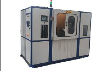
Withstand Voltage Test (Dielectric Voltage Withstand Test): Principles, Purposes, and Applications
The principle of withstand voltage test:
Withstand voltage test, also is called dielectric voltage withstand test, is a testing method for measuring the conducting performance of a device and its resistance to high voltage charge damage, mainly used for detecting electrical safety. It can be used for both regular circuit products and prototype for new development, providing guarantee for further safe usage. Withstand voltage test uses high voltage pulses to test the insulation performance of the tested system to see whether short circuits or overloads will occur. The settings of test conditions will directly influence the accuracy and reliability of the test results. Therefore, prior to testing, parameters should be studied and calculated carefully to ensure test accuracy.
What is hipot testing used for?
Hipot testing is a non-destructive test used to check the insulation capability of tested products under instantaneous high voltage environment. This test requires keeping a certain degree of high voltage in fixed time in order to ensure the strong and effective insulation performance of tested equipment. Besides, withstand voltage test can also detect some defects in the manufacture process of the instrument, such as deficient creepage distance and electric clearance, etc. Withstand voltage test is an important test which can quickly and accurately determine the capability of tested equipment against instantaneous high voltage in order to ensure the security and reliability of the tested equipment.
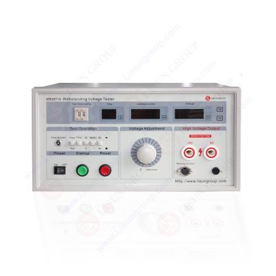
With the development of science and technology, the new type withstand voltage testers have enough of source voltage and load regulation rate, so the withstand voltage testers with capacity of 500VA have been eliminated from the new safety standards. In addition, this has brought threats to the operators’ operations, under different test requirements and large quantities of test processes, the withstand voltage testing equipment requires stronger performance, and the testers based on transformer and voltage regulator are no longer applicable.
Now, the new type withstand voltage testers can be divided into two types: one is composed of single-chip computer as the core, digital control waveforms combined with linear power amplifier; the other type is composed of single-chip computer core and SPWM (sinusoidal pulse width modulator) pulse generator , combined with IGBT (insulated gate bipolar transistor) pulse power amplifier, making it have stronger test capabilities. Not only it meets the requirements of different standards and large quantities of test processes, but it can also detect potential problems of the tested articles’ insulation performance such as arc, creepage and flash-over better. Thus, the new generation of withstand voltage testers are rapidly popularizing, continuously improving the safety performance of electronic equipment.
The withstand voltage test equipment has a complex structure, and its reliability and anti-interference ability depend on the design and quality of the electronic components. It has small distortional waveform, variable output frequency (50/60Hz), wide output voltage adjustment range and high control accuracy, can produce stable output voltage within the power range, not affected by load change, and can reach 500W output power. Besides, this instrument can also achieve automatic protection, and it can still operate safely even if there is no voltage output, which can help detect potential problems of the tested articles’ insulation performance such as arc, creepage and flash-over.
In addition, withstand voltage tester can achieve various standard requirements through the software, such as step up voltage, timed up voltage, constant speed up voltage, etc., and can also conduct breakdown point analysis, with breakdown protection and high display resolution leakage current display, which is particularly suitable for testing electrical appliances or components with high standards. Moreover, it is stable when working, can be networked with computers, thus realizing test statistical and sorting work, and can continuously test the tested articles.
The withstand voltage testing equipment is an important electronic testing equipment, which is mainly composed of AC (DC) high voltage power supply, timer controller, test circuit, display circuit and alarm circuit, etc. The working principle of this equipment is to measure the leakage current of the tested instrument by outputting the high voltage test, and to compare it with the preset judgment current. If the detected leakage current is lower than the predetermined value, the instrument is tested OK; while if the detected leakage current is greater than the preset judgment current, the test voltage will be cut off instantaneously, accompanied by sound and light alarm, and finally to determine the withstand voltage strength of the tested instrument. The technical specifications of this equipment mainly include output voltage and preset cut-off current, while the analog indicator type withstand voltage tester is generally characterized by its voltage magnitude in the form of allowable error.
Lisun Instruments Limited was found by LISUN GROUP in 2003. LISUN quality system has been strictly certified by ISO9001:2015. As a CIE Membership, LISUN products are designed based on CIE, IEC and other international or national standards. All products passed CE certificate and authenticated by the third party lab.
Our main products are Goniophotometer, Integrating Sphere, Spectroradiometer, Surge Generator, ESD Simulator Guns, EMI Receiver, EMC Test Equipment, Electrical Safety Tester, Environmental Chamber, Temperature Chamber, Climate Chamber, Thermal Chamber, Salt Spray Test, Dust Test Chamber, Waterproof Test, RoHS Test (EDXRF), Glow Wire Test and Needle Flame Test.
Please feel free to contact us if you need any support.
Tech Dep: [email protected], Cell/WhatsApp:+8615317907381
Sales Dep: [email protected], Cell/WhatsApp:+8618117273997
Read the full article
0 notes
Text
Ultraviolet Phototherapy Instrument, Global Market Size Forecast, Top 9 Players Rank and Market Share
Ultraviolet Phototherapy Instrument Market Summary
According to the new market research report “Global Ultraviolet Phototherapy Instrument Market Report 2023-2029”, published by QYResearch, the global Ultraviolet Phototherapy Instrument market size is projected to reach USD 490.6 million by 2029, at a CAGR of 6.2% during the forecast period

Figure. Global Ultraviolet Phototherapy Instrument Market Size (US$ Million), 2018-2029

Based on or includes research from QYResearch: Global Ultraviolet Phototherapy Instrument Market Report 2023-2029.
Market Drivers:
Rising prevalence of skin diseases. According to relevant statistics, the incidence of vitiligo in various countries and regions around the world is 0.5% to 2%, and the total number of patients worldwide is estimated to exceed 100 million.
Growing awareness about advanced phototherapy and developing healthcare infrastructure in Asian countries, such as China, India, and Indonesia.
Due to the development of science and technology, there are already various ultraviolet phototherapy instruments of different specifications on the market. A variety of irradiation equipment can be selected for different patients and different diseased parts, from local patients to systemic patients, and even individual parts can be treated with corresponding equipment.
Restraint:
The COVID-19 pandemic has posed a significant challenge for ultraviolet phototherapy instrument as manufacturing services, and distribution channels are inactive worldwide.
Medical device supervision is becoming stricter.
Side effects associated with phototherapy. The equipment used for the phototherapy treatment doesn’t succeed in particular times, and this factor is expected to restrain the global ultraviolet phototherapy instrument market growth.
Opportunity:
Ultraviolet phototherapy instrument is anticipated to show significant growth over the forecast period due to the availability of cost-effective products.
The prevalence of skin diseases such as vitiligo and psoriasis continues to rise, leading to a broad downstream market and increasing demand.
Due to the low technical difficulty and low cost, a large number of small and medium-sized enterprises will enter the market. During the forecast period, we expect this competition to intensify with an increase in product extensions.
Figure. Ultraviolet Phototherapy Instrument, Global Market Size, The Top Five Players Hold 44% of Overall Market

Based on or includes research from QYResearch: Global Ultraviolet Phototherapy Instrument Market Report 2023-2029.
In 2022, the global top five Ultraviolet Phototherapy Instrument players account for 44% of market share in terms of revenue. Above figure shows the key players ranked by revenue in Ultraviolet Phototherapy Instrument.
Figure. Ultraviolet Phototherapy Instrument, Global Market Size, Split by Product Segment
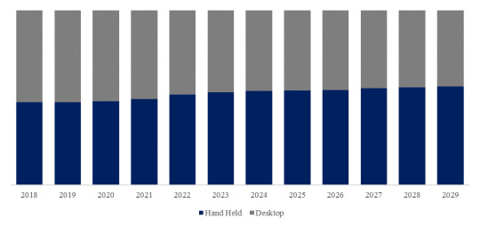


Based on or includes research from QYResearch: Global Ultraviolet Phototherapy Instrument Market Report 2023-2029.
In terms of product type, Hand Held is the largest segment, hold a share of 52%.
Figure. Ultraviolet Phototherapy Instrument, Global Market Size, Split by Application Segment
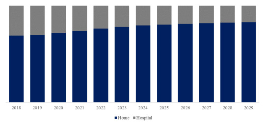


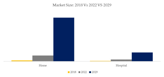
Based on or includes research from QYResearch: Global Ultraviolet Phototherapy Instrument Market Report 2023-2029.
In terms of product application, Home is the largest application, hold a share of 76%.
Figure. Ultraviolet Phototherapy Instrument, Global Market Size, Split by Region
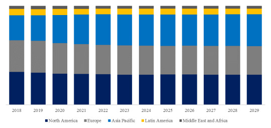


Based on or includes research from QYResearch: Global Ultraviolet Phototherapy Instrument Market Report 2023-2029.
About The Authors
Junping Yang - Lead Author
Email: [email protected]
Junping Yang is a technology & market senior analyst specializing in semiconductor devices, materials, and equipment. Yang has 9 years’ experience in semiconductor and focuses on ICs, semiconductor materials, package & testing, power semiconductor (IGBT, SiC, diode, MOSFET, modules and discrete), compound semiconductor (SiC, GaN, etc.), power, RF, optoelectronics, ceramic substrates (HTCC, LTCC, DBC, AMB, DPC, DBA), CMP, equipment & parts (wafer transfer robot, EFEM/Sorter, heaters, etc.). He is engaged in the development of technology and market reports and is also involved in custom projects.
About QYResearch
QYResearch founded in California, USA in 2007.It is a leading global market research and consulting company. With over 16 years’ experience and professional research team in various cities over the world QY Research focuses on management consulting, database and seminar services, IPO consulting, industry chain research and customized research to help our clients in providing non-linear revenue model and make them successful. We are globally recognized for our expansive portfolio of services, good corporate citizenship, and our strong commitment to sustainability. Up to now, we have cooperated with more than 60,000 clients across five continents. Let’s work closely with you and build a bold and better future.
QYResearch is a world-renowned large-scale consulting company. The industry covers various high-tech industry chain market segments, spanning the semiconductor industry chain (semiconductor equipment and parts, semiconductor materials, ICs, Foundry, packaging and testing, discrete devices, sensors, optoelectronic devices), photovoltaic industry chain (equipment, cells, modules, auxiliary material brackets, inverters, power station terminals), new energy automobile industry chain (batteries and materials, auto parts, batteries, motors, electronic control, automotive semiconductors, etc.), communication industry chain (communication system equipment, terminal equipment, electronic components, RF front-end, optical modules, 4G/5G/6G, broadband, IoT, digital economy, AI), advanced materials industry Chain (metal materials, polymer materials, ceramic materials, nano materials, etc.), machinery manufacturing industry chain (CNC machine tools, construction machinery, electrical machinery, 3C automation, industrial robots, lasers, industrial control, drones), food, beverages and pharmaceuticals, medical equipment, agriculture, etc.
0 notes
Text
Car companies demand a 20% price cut! What impact will it have on the SiC industry?
At the beginning of 2024, BYD launched a plug-in hybrid car for only about 70,000 yuan. Many car companies such as Nezha and Changan quickly followed suit and cut prices one after another. The price war continued throughout 2023 and became more and more intense.
As car prices drop, the pressure is also directly passed on to upstream parts suppliers. To borrow the recent words of Zhang Yong, CEO of Nezha Automobile, "pass the cold to everyone."
Recently, Xu Daquan, President of Bosch China, revealed in an interview that car companies will put more pressure on suppliers to reduce prices in 2024. "The requirements are all to reduce prices by 20%… In the past, the price reduction was usually 3%-5% per year." Under the extreme pressure, many auto parts suppliers were "sweating profusely" and shouted that they couldn't stand it. Bosch reluctantly said that the result of shutting down and not doing anything might be better than a 20% reduction; while Nidec and Freya made it clear that they would shift their focus from China to other markets.
However, it may not be a wise move to blindly ask suppliers to reduce prices. How can we not only reduce vehicle costs but also improve vehicle performance? I think there are 3 cost reduction paths:
Use new technologies to reduce the overall cost of the vehicle. For example, using 800V+SiC is expected to reduce the cost of the vehicle by 30,000 yuan;
Starting from other electronic control components, such as switching to film capacitor solutions, it is estimated that the cost of capacitors can be reduced by 4 times;
Actively introduce Chinese-made components from Yongming Electronics and other companies to further reduce vehicle manufacturing costs.
Below we will analyze them one by one so that you can see if they are reasonable.
SiC is expected to turn the tide and reduce costs and increase efficiency for new energy vehicles
Under the wave of price cuts for new energy vehicles, SiC semiconductors, as a key component of the main drive inverter, are also under great pressure. However, SiC will have multiple benefits in the future, including:
Taking up most of the market share of automotive IGBT modules, the market growth is huge;
Upstream substrates, chip production capacity and yield rates continue to improve, and SiC modules have certain room for price reduction;
New technologies can be used to reduce the usage and cost of SiC chips for electric drives.
At present, many car companies have achieved optimization of SiC main drive costs. For example, Nissan's new generation SiC electric drive system cost has been reduced by 30%, Tesla's main drive SiC has been reduced by 75%, and Xpeng's new electric drive has reduced carbonization by 30%. Silicon cost reduced by 50%…
More importantly, even under the current high price situation, SiC technology can "decompress" automobile companies and significantly reduce the cost of car manufacturing.
The general consensus in the industry is that new energy vehicles using SiC as main drive can increase vehicle battery life by 3%-10%. According to Bloomberg data, the industry average price of automotive power batteries in 2023 will be US$139/kWh. Based on this calculation, a 98kWh 800V model can save US$681-1362 (approximately RMB 4898-9797) in battery cost alone.
Li Xiang, chairman and CEO of Li Auto, said at the 2023 spring media communication conference that medium and large SUVs usually require 100kWh battery capacity to achieve a cruising range of 600 kilometers, but Li Xiang achieves the same through "800V platform + SiC technology + drag coefficient optimization" The cruising range only requires 80kWh, and the cost of a bicycle can be reduced by about 30,000 to 40,000 yuan.
Therefore, in the context of a car price war, the SiC supply chain must speed up cost optimization, and car companies and Tier1 should also speed up the introduction of SiC technology.
Thin film capacitors help silicon carbide enter the car, further alleviating cost anxiety
The largest cost of electric vehicles is the power battery (accounting for about 38%), and electronic control accounts for about 6%. According to Infineon's estimates, power semiconductors (IGBT/SiC, etc.) account for about 40% of the cost of electronic control, followed by DC-Link capacitors, which account for about 16% of the cost.
Therefore, in addition to SiC modules, low-cost DC-Link capacitor solutions are also beneficial to reducing electric drive and electronic control costs, and can alleviate the cost anxiety of car companies to a certain extent.
According to Nrel and Myavnet reports1, in a 30KW, 650V DC link, only 4 film capacitors need to be used. If replaced by electrolytic capacitors, 10 devices are required. It is estimated that the price of 4 film capacitors is lower than 10 aluminum electrolytic capacitors. The capacitance is more than 4 times lower and the volume is 15 times smaller.
In addition, according to Yongming Electronics, to give full play to the advantages of SiC, it is also necessary to match suitable capacitors for electronic control.
This is because new energy vehicles require higher power density and smaller size of motor controllers, and power modules are gradually shifting from traditional silicon-based IGBT modules to SiC MOSFET modules. However, the switching frequency of SiC modules is very high, with the highest switching frequency reaching 30 kHz. Excessively high peak current will increase the high-frequency component of the capacitor ripple current and cause more serious heating. Therefore, silicon carbide electronic control also puts forward more stringent conditions and higher requirements for the temperature rise of the capacitor at high frequencies. .
The resonant frequency of electrolytic capacitors is only 4kHz, which is not enough to absorb the current ripple of SiC electronic control. Moreover, because the electrolytic capacitor core itself generates high heat and has a lifespan that decays too quickly, and has poor corrosion resistance, it is difficult to use it in new energy vehicles. Popularize application. In comparison, film capacitors have better temperature characteristics, can withstand the same reverse voltage, have lower equivalent series inductance (ESL) and equivalent series resistance (ESR), longer service life and more High safety and reliability. For example, on DC-Link, electrolytic capacitors are one of the most likely places to cause failure of electronically controlled inverters. In contrast, the life of film capacitors is generally more than 10 years. Therefore, film capacitors are widely used in the field of new energy vehicles.
Data shows that the installed base of main drive electronic controls based on DC-Link film capacitors will reach 5.1117 million units in 2022, accounting for 88.7%, indicating that film capacitors have replaced electrolytic capacitors and become the mainstream of the electric drive market.
In addition to main drive electronic control, film capacitors have become increasingly popular in many fields such as vehicle power supplies and optical storage and charging. According to Tsinghua University estimates, the global demand for film capacitors will increase from 827 million in 2019 to 991 million in 2024.
Made in China further reduces the cost of capacitors, Yongming promotes the development of new energy with innovation
According to sources in the capacitor industry, the current single price of film capacitors used in new energy vehicles is about 200 yuan, and the average electronic control of a new energy vehicle requires 1.3 film capacitors, worth nearly 300 yuan. Film capacitors for vehicle OBC and other components The value is about 70 yuan, and the film capacitor in a car is worth nearly 400 yuan, which is also a considerable cost.
In response to the urgent cost reduction needs in fields such as new energy vehicles, Yongming Electronics recently launched the MDP and MDR series of DC support film capacitors. By using advanced manufacturing processes and high-quality materials, they can perfectly adapt to global power semiconductor leaders such as Infineon. The working conditions of Sheep's SiC MOSFET and silicon-based IGBT will further promote the new energy industry to achieve cost reduction and efficiency improvement.
It is understood that Yongming Electronics' MDP and MDR series film capacitors have several outstanding features: lower equivalent series resistance (ESR), higher rated voltage, lower leakage current and higher temperature stability.
First of all, Yongming Electronics' film capacitors adopt a low ESR design, which can effectively reduce the voltage stress during switching of SiC MOSFET and silicon-based IGBT, reduce the loss of the capacitor, and improve the efficiency of the entire system. At the same time, the capacitor also has a higher rated voltage, which can withstand higher voltage working conditions and ensure the stable operation of the system.
According to reports, the capacity ranges of Yongming Electronics' MDP and MDR series film capacitors are 5uF-150uF and 50uF-3000uF respectively, and the voltage ranges are 350V-1500V and 350V-2200V respectively.
Secondly, Yongming Electronics’ latest film capacitors have lower leakage current and higher temperature stability. Taking the electronic control of new energy vehicles as an example, its power is usually large, which causes the film capacitor to heat up more seriously, which will reduce the life and reliability of the film capacitor. To this end, Yongming's MDP and MDR series are based on high-quality materials and advanced manufacturing processes to design better heat dissipation structures for film capacitors, so that the capacitors can maintain stable performance in high-temperature environments and will not be damaged due to temperature rise. Cause the capacitance value to drop or fail. In addition, capacitors have a longer service life and can provide more reliable support for power electronic systems.
Third, Yongming Electronics’ MDP and MDR series capacitors also have smaller size and higher power density. Taking the 800V electric drive system as an example, the technical trend is to use SiC devices to reduce the size of passive components such as capacitors, thereby promoting the miniaturization of electronic controls. Yongming adopts innovative thin film manufacturing process technology, which not only improves the integration and efficiency of the entire system, but also reduces the volume and weight of the system, providing more possibilities for device portability and flexibility.
Taken together, Yongming Electronics' DC-Link film capacitor series products have a dv/dt tolerance increased by 30% and a lifespan increased by 30% compared to other film capacitors on the market. They can not only provide SiC/IGBT circuits Providing better reliability can also provide better cost-effectiveness and break the price barrier in the popular application of film capacitors.
As an industry pioneer, Yongming Electronics has been deeply involved in the field of capacitors for more than 20 years. Its high-voltage capacitors have been stably used in high-end fields such as vehicle OBC, new energy charging piles, photovoltaic inverters, and industrial robots for many years. The launch of a new generation of film capacitor products this time has solved various problems such as film capacitor production process control, tooling and fixture equipment. It has completed reliability certification at leading global companies, achieved large-scale application, and provided services to larger customers. Prove product reliability. In the future, they will use their long-term technology accumulation and precipitation to help the rapid development of the new energy industry with highly reliable and cost-effective capacitor products.
0 notes
Last Seen Blogs

femmfaetale
give ‘em hell, kid

painlesslyrich
CAN I GIVE UP?

kinanchi
Kinanti Zuha Larasati

caroline-57
You fall in love with people’s mind

az-rid
AZ-RIT