#LMS 6202
Explore tagged Tumblr posts
Visit Tumblr Blog
Explore Tumblr blogs with no restrictions, modern design and the best experience.
Last Seen Tumblr Blogs


Fun Fact
70% of Tumblr users say the Dashboard is their favorite place to spend time online.
Text
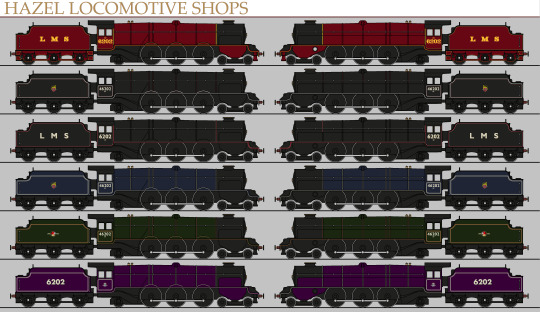
Presenting the LMS 6202, the Turbomotive!
20 notes
·
View notes
Text
NWR #25 and #26: The Sodor Turbomotives.

The Sodor Turbomotives 1 and 2, AKA Orkney and Andreas respectively, are identical Pacific Steam Turbine locomotives, who work on the NWR. Orkney, who despite her name, is actually a girl, was originally the LMS Turbomotive #6202, built at Crewe Works in 1935. She was surprisingly down to earth for a express engine, especially compared to other LMS engines such as Lord Rathmore (later Big City Engine) and Princess Elizabeth, probably due to the fact that like most steam turbines, she had a really big problem with running at low speeds. This really didn't bother her too much however, and she often stood up for the little guys on the LMS. In 1946 however, one year after WW2, she was trialed on the NWR after Gordon broke down and was sent away for repairs. After doing quite well, she was purchased by the NWR later that year, and later got upgraded to be more efficient at Crovan's gate works. In 1949, her younger twin brother "Sodor Turbomotive 2", named Andreas after the last king of sodor, was built as another reserve express engine, and made so She didn't feel lonely as the only member of her class. In 2019, the two turbomotives were given the numbers 25 and 26 respectively, after sporting no numbers prior. Andreas is a Friendly yet timid and insecure engine, doubting if he could be as good as a normal steam locomotive most of the time, but he always has his older sister Orkney by his side, and the two care for and support each other a lot, "a bond as strong as iron" they would say. Since 2013, they have also been given there own express trains.
And before you ask, my AU's 6202 was purchased in 1946, before she was rebuilt into a LMS Coronation Class and destroyed in the Harrow and Wealdstone Crash of 1952 in real life.
#thomas and friends#thomas and friends au#thomas the tank engine#ttte#au#oc#ttte AU#ttte oc#LMS turbomotive#turbomotive#Orkney TTTE#Andreas ttte#Sodor Turbomotives#steam turbine#steam turbine locomotives
3 notes
·
View notes
Note
Max, and LMS 6202 Black engine with green stripes was approaching the big station and smiled relaxingly. He looks over to Sally and smiled. "Hello there" he toots with gentleness
Sally looked over to see who was speaking to her. She had never seen an engine this big before, let alone as big as Gordon or Henry.

“Oh...!”

She regains her composure and gives him a returning smile.
“Uh, hello!”
100 notes
·
View notes
Text
The Black Wolf
The Black Wolf was the flagship train from London to Gunnigrind. Launched in 1931 with the allocation of Royal Scot class locomotives, the about 650 mile journey taking around 16 hours, departing from their termini at 6:00 PM, and arriving at 10:00 AM the next morning.
The Black Wolf was a beast of a train, usually consisting of fourteen coaches (up until the BR days, this often included one of the LMS ex-Pullman dining cars, one rake usually had 216, the other having 219). The usual makeup had a brake coach, the dinner, two first class sleepers, two third class sleepers, three composite corridor coaches, and a third brake (later composite brake), then another first and third sleeper, a composite coach, and finally another third (later composite) brake. These final four coaches were to take up the Ben Fisag Branch.
Starting in 1933, Princess Royal class pacifics occasionally headed the train, and the Turbomotive was a common sight. In 1935 when Gunnigrind had 6204 allocated to its shed, and 6202 and 6204 largely took over The Black Wolf from the Royal Scots, although as the shed lacked a spare Pacific, they could not tighten the timetable in case of loco failures.
This changes in 1937 with the arrival of Coronation Class 6225, and so the schedule was tightened by a whole hour!
The second world war put a pause on named trains, however a similar train ran, carrying troops and people fleeing the London blitz.
In December 1947, Coronation class 6526 arrived in the island, and so the train became an almost exclusively Duchess hauled affair, although when BR 10001 arrived in July 1948, her and her LMS twin were trialled on the service, and were a regular sight doubleheading until 1949.
Also in 1949, 6202, now 46202, while climbing the bank out of Gunnigrind with the southbound Black Wolf, experienced a catastriphic turbine failure, leading to her rebuild.
On October 8, 1952, 46202, with the northbound Black Wolf, collided with an out of control stone train coming from the Ben Fisag Branch, resulting in the near destruction of both the engine hauling the goods train, 42724, and 46202, which were both written off, as well as the death of seven on the Black Wolf: both the driver and fireman, a guard, two cooks and two passengers in the dining car.
In 1954 71000 was constructed and allocated to Gunnigrind, and at first was incapable of hauling The Black Wolf satisfactorily due to design and construction flaws, which were able to be rectified at the small works in Gunnigrind that had been constructed by the LMS to repair experimental engines that were being tested on Seidrey.
In the late 1950s, Class 40s began to be allocated to The Black Wolf, and started to displace the steam locomotives from the service. However, the Class 40s had to doublehead the train to keep to time and to not overheat their engines while climbing the numerous gradients.
Because of displacement by diesel and the looming ban on near all LMS express steam traction south of Crewe due to electrification, the final steam hauled Black Wolf departed London Euston on the evening of 31 August 1964.
In 1961 the LMS sleeping cars were finally replaced by BR Mark 1s, and the train mostly stayed that way, due to utilizing composite coaches and there being no direct Mark 2 replacement.
Starting in 1966 The Black Wolf has an engine change at Crewe to an electric locomotive.
Also in 1966 the final four carriages of the consist were dropped, as the Ben Fisag Branch closed. Later the same year, Motorail service was introduced.
The Class 40s didn't last long on The Black Wolf, as they were found to be somewhat underpowered for the service. They were replaced by Class 50s in 1967, which were much more satisfactory.
In 1974, the engine change to electric traction was moved to Glasgow. Although most Class 50s has been moved to the Western Region, three had stayed behind to haul the Black Wolf
In 1977, the full brake and all the chair coaches were dropped, except for the brake composite, which was finally replaced by a mark 2 brake second open to be used solely as a lounge, leaving the train to consist merely of six coaches, not counting the Motorail flats. In 1979 the mark 1 sleepers were replaced by mark 3s.
The Black Wolf continued on in this form until its discontinuation in 1989, bringing to an end the saga of the longest distance individual train in Britain, The Black Wolf.
On June 4th, 1996, The Black Wolf name was revived, as a six to eight car segment of the Caledonian Sleeper to Gunnigrind, hauled by Class 47s until 2001, then Class 67s until 2016, when they started using Class 73/9s, which they use through the present day.
1 note
·
View note
Text
Sabroe 120 Manual

Sabroe 120 Manual Pdf
INSTRUCTION MANUAL FOR PISTON COMPRESSOR
SABROE prescribes operating limits within which the compressor and any additional equipment must operate. These limits for R717, R22, R134a, R404A, R507 and R407C are shown in the following tables, together with the main data for the compressor. Parts Supply for IR Europe - Sabroe Spare parts manual - SAB 120 and SAB 151 A-Frame 008504 en 2019.12 5/42 Spare parts liste SAB 120, 151 A-frame Abbreviations in this manual include: Ang. Angle OD= outside diameter equal to Ass. Cooling medium refrigerant Cp. Compressor Reg regulating DN (+space).
You can find detailed information on our website: http://coolref.ru/EN
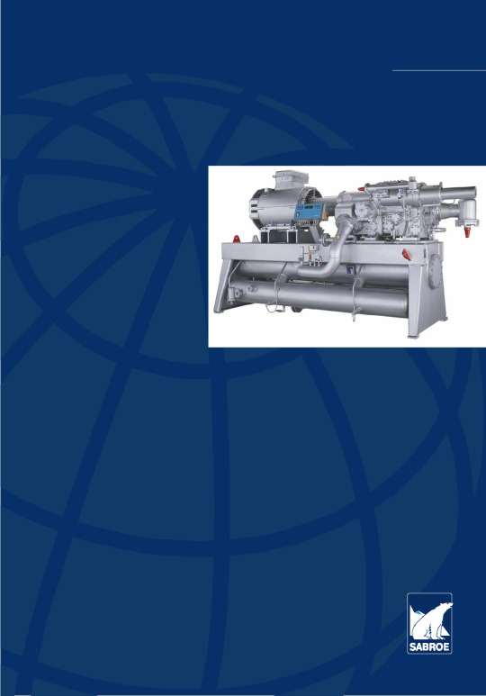
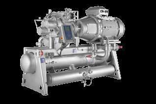
Description of SAB 202
The SAB 202 compressor is a capacity adjustable screw compressor with oil injection. The two rotors are equipped with 4 lobes (male rotor) and 6 lobes (female rotor), respectively, executed with asymmetric profile according to SRM licence. As indicated on the spare parts drawing at the end of this manual, the rotors at the suction end are fitted with slide bearings, whereas the bearing at the discharge end consists of a combined bearing set with slide bearings, absorbing the radial load, and ball bearings, absorbing the axial forces. The axial forces are partly relieved by means of the rotating balance pistons mounted on the rotors. The rotors are designed for both male drive and female drive. The driving rotor is fitted with a shaft.
The compressor is fitted with a large built-in suction filter, which effectively prevents dirt particles from the refrigeration plant from being led with the suction gas into the compressor. The suction filter housing also has a built-in compressor protection valve which - controlled by a pilot valve - safeguards the compressor against any unwanted high compression pressures. For efficient filtration of the oil that lubricates the bearings in the compressor, an oil filter cartridge has been inserted in the compressor block.
Furthermore, the compressor contains a built-in non-return valve, preventing the compressor from running backwards whenever the power to the driving motor is disconnected. The driving shaft is fitted with a shaft seal of the slide ring type, consisting of a fixed cast iron ring with an O-ring sealing against the shaft seal cover and a rotating springloaded carbon ring with O-ring sealing against the shaft. It is possible to regulate the compressor capacity steplessly from approx. 10% to 100% by means of a regulating slide mounted under the rotors. Once the slide has moved away from the slide stop a gap is created so that some of the sucked-in gas is returned to the suction side. The bigger the gap, the lower the compressor capacity. The regulating slide is moved hydraulically by a regulating piston and controlled by a solenoid valve system. The compressor also features a regulating system by which the built-in Vi volume ratio can be adjusted. The result hereof is that the compressor works optimally at varying operational pressures in the plant.
To optimize the compressor volume ratio the position of the Vi regulating slide must be changed whenever the compressor works at max. capacity. This is done by changing the position of the slide stop. At partial load the Vi volume ratio will only be approaching the optimum. Regulating the built-in Vi volume ratio can be done in the following two ways, depending on the compressor type Manual regulation of the Vi slide:
By turning the spindle, pos. 180, in accordance with the curves in the instruction manual.
By means of the oil pressure and two solenoid valves, controlled by a UNISAB II control system.
Schemes
Spare parts for compressor SAB 202
Sabroe 120 Manual Pdf
List of parts for SAB 202Relevant drawing 0661-855PosDesignationNoPart noComplete compressor LF, aut. Vi4161-059Complete compressor LF, man. Vi4161-060Complete compressor LM, aut. VI4161-061Complete compressor LM, man, Vi4161-062Complete compressor SF, aut. VI4161-063Complete compressor S F, man. Vi4161-064Complete compressor SM, ant, Vi4161-065Complete compressor SM, man. Vi4161-066Compressor housing10-1Compressor housing (L)13011-00910-2Compressor housing (S)13011-019Bearing cover at suction end20-1Bearing cover, female drive13013-08920-2Bearing cover, male drive13013-11021O-ring dia. 430,66 x 3,53, neoprene11331-11722Innar sleeve, INA IR dia. 17/20 x 1621514-01823Washer dia. 25/16.5 x 442114-04724mreaded plug with cottar 1/211343-02725Dowty ring 02511331-43026Cylindrical screw M16 x 60101413-43627Cylindrical screw M 16 x 3021413-42928Cylindrical screw Ml 6 x 18081413-42830Hose connection11345-143Bearing cover at ditcharge end40Thrust cover/capacity regulating cylinder13013-15041Cylinder screw M16 x 60201413-43642Washer dia. 35/16,5 x 442114-04743O-ring dia. 151,93 x 3,53, neoprene11331-09944Adjusting screwa2111-12845Locking screw M6 x 1041413-23146Cross bar for bearing adjustment13083-13747Cylinder screw M12 x 3061413-36648Inner sleeve, INA IR dia 17/20 x 1621514-01849O-ring dia. 13,94 x 2,6211331-014Cover for capacity regulating cylinder60Cover for capacity cylinder13013-19761O-ring dia. 142,47 x 3,53 - neoprene11331-09662Cylinder screw M12 x 3541413-387Housing for capacity indicator70Housing for capacity indicator13045-00271Cylinder screw M6 x 3041413-34372Cover for capacity indicator13045-00373Cylinder screw M6 x 5041413-34774O-ring dia. 98.02 x 3,53, neoprene11331-08175-1Glass for indicator (L)t3045-05075-2Glass for indicator (S)13045-049Rotors110-1Set of rotors tor SM13024-102110-2Set of rotors tor SF13024-097110-3Set of rotors for LM13024-103110-4Set of rotors for LF13024-095111Journal bearing41515-031112Retaining pin for journal bearing dia, 5 x 4541446-033113Cylinder screw M6 x 4581413-340114Thrust washes23021-029115Cylinder screw M16 x 4521413-433132Four point ball bearing dia. 70/150 x 3521513-040133Set of shims dia. 128/150 for adjusting the clearance between the rotor and outlet port. Comprising: 1 off thickness 5,60 mm 23021-0431 - 5,65 mrr 1 - 5,70 mm1 - 5,75 mm1 - 5,80 mrn1 - 5,85 mm1 - 5,90 mm134Balance piston. drive rotor13025-052135Spacer ring, drive rotor13025-035136Retaining ring 4 x 1011446-012137Balance piston, driven rotor13025-034138Spacer ring, driven rotor13025-036139Retaining pin 5x1611446-021DIscharga ports140-1Discharge port for male rotor .13031-031141-1Discharge port for female rotor13031P032142Cylinder scraw M8 x 19061413-309143Washer for discharge port dia. 16,5 /8,2 x 1062114-045144Cylinder screw M6 x 3021413-343145Pointed screw M10 x 35 - inside adjustment21413-255146Locking screw M10 x 10 - inside adjustment21413-253147Locking screw M10 x 10 - outside adjustment21413-253148Pointed screw M10 x 20 - outside adjustment21413-032149ABlank of screw 3/8' - outside adjustment21343-026149BGasket - outside adjustment21331-427Parts for adjusting rotors153Inner cover23021-030154O-ring dia. 142,47 x 3,5321331-096155Cylindrical steel roll 8H 11 x 8S1514-019Shaft seal160AShaft seal collar 1160BShaft saal seat 1160CO-ring for shaft seat collar 113084-557160DO-rlng for shaft saal seat 1160EPointed screw 3161Retaining pin for shaft seal seat dia. 3 x 511446-005162Spirolox ring (oil thrower)11437-294163-1Cover, F13013-100163-2Cover, M13013-102164O-ring dia, 132,94 x 3,53, neoprene11331-093165-1Cover for shaft seal, F13013-099165-2Cover for shaft seal, M13013-101166O-ring dia, 158,34 x 3,5311331-100167Cylinder screw M12 x 3581413-387168Hose connection branch 1 /4°11345-143169Clear plastic hose11241-190Suction filter170Suction filter13042-075Adjusting system for Vi-slide, AUT352Screw for transmitter M3 x 8 (included in pos. 410)(4)1412-012371Sealing ring OD 7011332-126372Attachment for pin13044-035380Cover tor aut. Vi13013-196381O-ring dia. 101,19 x 3,53, neoprene11331-083382Cylinder screw M12 x 3541413-387384Attachment for sealing ring13044-034385Cylinder screw M4 x 1621413-320386Cylindrical pin dia. 6 x 1621445-076387Cylinder screw M6 x 1211413-339390Spindle aut. Vi13044-063393Ball baaring 620211511-012395Driving disk13044-021396Cylinder screw M4 x 1211413-318400Attachment tor transmitter13044-064401Cylinder screw M6 x 8041413-307402Cover ring for transmitter13045-009403Cylinder screw M4 x 1041413-319405Magnetic coupling13045-062406O-ring dia. 32,99 x 2,62 (incl in pos. 405)(1)1331-133407Hexagon head screw M4 x 16 (inc. in pos. 405)(1)1413-320410Turning transmitter13448-004411Driving lug13044-020412Pointed screw M4 x 511413-211413Clamping pin dia. 1,5 x 1211446-010Adjusting system for Vi-slide, MAN180Spindle man. Vi13044-052181Cover for man. Vi13013-093182Sealing washer for slide stop13044-014183Sealing ring11331-503184O-ring dia. 44,04 x 3,53, neoprene11331-065185Retainer for bearings13044-033186Axial ball bearing dia. 42/25 x 1121512-015187Locking plate12114-043188Cylinder screw M6 x 1211413-339189Thread washer13044-073195Cylinder screw M4 x 3021413-325196Cylinder screw M6 x 3531413-344197O-ring dia. 101,19 x 3,5311331-083198Cylinder screw M12 x 3541413-387Vi-slide190-1Slide stop, S13043-131190-2Slide stop, L13043-130191-1Spring for Vi-slide,L12144-042191-2Spring for Vi-slide,S12144-043192Cylinder screw M 10 x 2511413-371Capacity regulating slide200-1Slide for L13043-113200-2Slide for S13043-125201Piston part inner13043-138202Piston part outer13043-139203O-ring dia. 40,87 x 3,53, neoprene11331-064204Sealing ring dia. 15011332-133206Slotted nut KM811514-200207A-1Piston rod for L13043-140207A-2Piston rod for S13043141207BBushing tor indicator spindle Included in pos. 207A13045-046207CCylindrical pin dia. 6 x 16 Included in pos. 207A11445-076207DSpirolox-ring Inducted in pos. 207A11437-291207ESteel ball 3/8' Included in pos. 207A11514-158208Locking plate for slotted nut11514-070209Tape bearing22132-100311Cap torew M20 x 6011424-289313Clamp13042-054Spindle for copacity indication210Spindle tor capacity indication13045-059216Magnetic coupling13045-061217O-ring dia. 44,12 x 2,62 (incl. in pos. 216)(1)1331-146218Hexagon head screw M4 x 16 (Incl. in pos. 216)(1)1413-320219Hexagon head screw M4 x 20 (ind. in pos. 216)(2)1413-322Capacity indication221Indication disk13045-001223Socket cap screw M4 x 1011413-319224Backing ring 105/90 x 1,612356-155226Locking washer DC 15/8,411437-054227Locking washar DC 8/4,311437-060350Position transmitter13448-004351-1Indicator glass, L (replacing pos. 75-1 when transmitter)13045-048351-2Indicator glass, S (replacing pos. 75-2 whentransmitter)13045-047352Screw for transmitter M3 x 8 (incl. in pos. 350)(4)1412-012Non return valveNon return valve complet3042-172252O-ring dia. 253,37 x 5,33, neoprene11331-181253Intermediate flange13013-288255Valve housing13042-127256Spindle guide13042-125257Retainer13042-126258Hexagon head screw M8 x 12031413-314259Valve cone13042-123260Spindle13042-124261Spring11523-033262Tape bearing dim 10 x 1 x 4612132-114263Tape bearing dim 10 x 1 x 105t2132-096264Hexagon head screw M16 x 7581424-108265Countersunk socket cop. screw M12 x 2511413-115266Hexagon bead scraw M12 x 3021413-386267Shaft nut KM9 - M4511514-201268Seeger ring dia. 14 x 1,0, DIN 47111437-207Oil injection316V-joint 22-RL11349-153317Check valve RVS11364-163318O-ring dia. 33,05 x 1,7811331-123319Valve seat13042-077External oil piping320-1Pipe sat (L)13049-026320-2Pipe set (S)13049-029321Pipe clamp dia. 3 x 1212532-012Oil filter450Oil filter coveri3041-008452O-ring dia. 132,94 x 3,53, neoprene11331-093453O-ring dia. 101,19 x 3,53, neoprene11331-083455Lock nut M1011433-030456Cylinder screw M12 x 3541413-387458Stay bolt for magnet12111-127459Magnets for oil filter41517-022460Intermediate ring43424-039461Rubber ring21334-012462Plug 1/4'21343-025463Dowty ring dia. 20,57 x 13,7421331-428470Oil filter cartridge11517-015475O-ring dia. 63,9 x 3,5311331-071476Cylinder screw M 12 x 3041413-386Oil flow swich500Terminal box11554-001501Cover for flow switch13041-004502O-ring dia. 132,94 x 3,53, nroprere11331-093505Nipple tor ftow switch o12314-106506Dowty ring11331-433507Flow switch with ball11553-024508Washer12114-046509Gasket dia. 19/14 x 1,512356-124510Spring12144-041511Circlip (included in pos. 507)1512Cylinder screw M12 x 3541413-387Plugging520Plug 1/2'11343-027521Dowty ring 02511331-430525Plug 3/4'11343-028526Dowty ring 02711331-433530Plug 1/4'11343-025531Gasket ring 19/14 x 1,512356-124Economizer inlet600Eco-plug13013-111601Cylinder screw M12 x 3041413-386602Cylinder screw M8 x 3021413-358603O-ring dia. 53,57 x 3,53, neoprene11331-058Relief valve700-1Back pressure independent valve. BSV 8-18 bar12416-202700-2Back pressure independent valve. BSV 8-22 bar12416-224Pilot operated valve701-AConnection line for POV 5013049-032701-BConnection line for POV 6013049-033702-ACylinder screw M12 x 2541413-385702-BCylinder screw M 12 x 3041413-388703-AO-ring dia. 63,09 x 3,5311331-071703-BO-ring dia. 88,49 x 3,5311331-079704-APilot operated valve, POV 50 (for R717)12417-046704-BPilot operated valve, POV 80 (for R22 and HCF,s)12417-058Cover for main valve705-ACover for POV 5013013-125705-BCover for POV 8013013-163706Cylinder screw M16 x 4081413-432707O-rlng dia. 253.37 x 5,3311331-181Connection between compr. discharge side and suction side710-AManifold for POV 5013013-124710-BMan (fold tor POV 8013013-157711-AO-ring dia. 85,32 x 3,5311331-078711-BO-ring dia. 86,49 x 3,5311331-079712-ACylinder screw M12 x 11031413-406712-BCylinder screw M12 x 3041413-386715-ACover (for POV 50 only)13013-125716Cylinder screw M16 x 4041413-432717O-ring dia. 164,69 x 3,5311331-101720-APipe conneclion for POV 5013014-002720-BPipe connection for POV 8013013-166721-ACylindar screw M12 x 3081413-386721-BCylinder screw M12 x 4041413-388722-AO-ring dia. 75,79 x 3,5321331-075722-BO-ring dia. 88.49 x 3,5311331-079Releif valve connections725Stud coupling A-12 RL11349-053726Al-gasket dia.24/13 x 1,512356-127727Reducer G3/4 - G3/812312-038729Elbow coupling VB 12-RL11349-210730Union nut G112313-017731Threaded nipple G3/812311-065732Al-gastet dia.30/16 x 1,512356-137733Dowty ring 02311331-427Signal trantducers751Pressure transducer, PT111373-249752Pressure transducer, PT311373-271753Pressure transducer, PT411373-271755Stud coupling21349-137756Stud elbow11349-233761Temperature transmitter, TT611373-264762Temperature transmitter, TT711373-264765Gasket ring21349-135766Reducer G1/2-G1/411349-077
S=L/D 1.7 M=Male drive L=L/D 2,2 F=Female drive
Spare parts survey for SAB 202 unitThe following list comprises all components that can be fitted on a compressor unit. From this list we have selected the components that are used on a particular unit and which are indicated on the piping diagram of this instruction manual. The position numbers on the piping diagram are a reference to the 'Pos.' columns of this list The piping diagram is dedicated to the compressor number stated on page 1 of this instruction manual.The components in the shaded areas are variable. This may be due to voltags, refrigerant, approved pressure etc.On ordering spare parts it may be an advantage to receive them in sets selectedfor your specific compressor unit.A list of sets can had on request from SABROE's local representative.
Pos.DesignationPart no.Regulating & Control deviceUNISAB IlPT1Pressure transducer -1 - 9 bar1373-243PT2Pressure transducer -1-25 bar1373-271PT3Pressure transducer -1 - 25 bar1373-271PT4Pressure transducer -1 -25 bar1373-271TT5-6-7Temperature transducer PT1001373-252TT5-6-7Temperatura transducer PT1001373-264(Avaible after 97.01.20)GT6Position transmittar (capacity)3448-004GT9Position transmitter3448-004UNISAB II Frontpanel1573-0071 CPU-Module1572-0261 Relay print1574-0161 EPROM extractor1613-0021 EEPROM extractor1613-0031 EEPROM1571-0153 Jumpers2 Fuses1572-0181 Screw driverRefrigerant systemSuction:20O-ring dia. 253,37 x 5,331331-181Set of gaskets for SCV 125 (M R717)3184-080Set of gaskets for SCV 150 (M R22/F R717)3184-081Set of gaskets for SCV200 (F R22)3184-0812434-35Sel of gaskets for SNV 82453-05347-48Oil separator, general:22O-ring dia. 164,69 x 3,53 (disch. flange)1331-10130Sealing ring dia. 42/49 x 6,51349-21330Heating rod, 250V3181-038-1Heating rod, 115V3181-039-1Heating rod, 230V3181-04031O-ring dia. 52,07 x 2,62 (Sight glass)1331-140Sight glass1226-01755O-ring dia. 329,57x5,33 (for cover)1331-184Oil separating element1517-079-2Oil return:52Nozzle valve1364-15153Sight glass1226-01453Gasket dia. 40,5/33 x 1,52356-144Discharge:204Set of gaskets for SCV 100 (M)3184-079Set of gaskets for SCV 100 (F)3184-097Safety valves:28DN 40/65Gasket dia. 75/61 x 2,02356-220Gasket dia. 109/95 x 2,02356-222O-ring dia. 91,67 x 3,53 (house)1331-080Conical seal for DN 40/651365-079Spring (for 25 bar opening pressure)1523-02728DN 50/80Gasket dia. 87/73 x 2,02356-221Gaskat dia. 120/106 x 2,02356-223O-ring dia. 117,07 x 3,53 (house)1331-088Conical seal for DN 50/801365-080Spring (for 25 bar opening pressure)1365-05028DN 65/100Gasket da. 109/95 2356-222Gasket dia. 149/1292356-224O-ring dia. 151,99 x 3,53 (house)1331-099Conical seal for DN 65/1001365-081Spring (for 25 bar opening pressure)1523-03528DN 80/125Gasket dia. 120/1062356-223 Gasket dia. 175/1552356-228Gasket for safety valve house DN 80/1251365-082Conical seal for DN 80/1251365-075Spring (for 25 bar opening pressure)1523-036Water-cooled oil cooler OWSG33OWSG 16xxGasket dia. 270/150 x 5,0 2355-171 Gasket dia. 107/61 x 2,02357-014Gasket dia. 36/28 x 1,52356-14133OWSG 21xxGasket dia. 310/205 x 5,02355-172Gasket dia. 142/90 x 2.02356-269Gasket dia, 36/28 x 1,52356-141O-ring dia. 34,52 x 3,531331-02833OWSG 27xxGasket dia.370/255 x 5,02356-173Gasket dia.162/115 x 2,02356-276 O-ring dia. 34,52 x 3,531331-028External oil filter type BGAH39Filter element1517-015O-ring dia. 169,3 x 5,7 (cover)1331-226O-ring dia. 130,2 x 5,34 (insert)1331-169O-ring dia. 109,2 x 5,7 (element)1331-225O-ring dia. 62,14 x 3,53 (collar)1331-077External oil filter type OF210839Filter element1517-015O-ring dia. 170,82 x 5.33 (cover)1331-175O-ring dia. 130,2 x 5,33 (insert)1331-169O-ring dia. 109,2 x 5,70 (element)1331-22538-42 Set of gaskets for SCV 503184-077Flange connection, oil tubeGasket dia. 87/73 x 2,02356-221O-ring dia. 63,09 x 3,53 (compr.)1331-071Oil by-pass (at pump)210Gasket dia. 140/105 x 1,5 (non-return valve)2356-10669O-ring dia. 50,40 x 3,53 (non-return valve)1331-300Thermostatic three-way valve, type RT646O-ring, Neoprene1331-384Thermo element (48 deg. C)1365-08470Solenoid valveValve housing EVM (NC)1372-335Gastet set for EVM1336-024Coil 10 W 220 V 50/60 Hz1372-537 110 V 50/60 Hz1372-538 240 V 50 Hz1372-53971Solenoid valveValve housing EVM{NO)1372-287Gasket set for EVM1336-024-02Coil 10 W 220 V 50/60 Hz1372-537 110 V 50/60 Hz1372-538 240 V 50 Hz1372-539Throttle valve1364-15173Solenoid valve - see pos.7074Solenoid valveValve housing EVM (NO) - see pos.71027B113080-84Gasket set for SVA 15-202453-02281Filter FA15 - When TEAT 20 is selectedGasket set for FA151377-078Repair kit for FA 151377-25081Filter FA20 - When TEAT 85 is selectedGasket set for FA201377-079Repair kit for FA201377-25182Solenoid valve EVRA15 - When TEAT 20 is selectedGasket set (for EVRA 15)1377-093Repair kit (for EVRA15)1377-099Coil 10 W 220 V 50/60 Hz1372-537110V 50/60 Hz1372-538240V 50 Hz1372-53982Solenoid valve EVRA20 - When TEAT 20 is selectedGasket set (for EVRA20)1377-094Repair kit (for EVRA20)1377-069Coil 10 W 220 V 50/60 Hz1372-537110 V 50/60 Hz1372-538240 V 50 Hz1372-53983Injection valve TEAT 20Nozzle insert 20-81371-203Nozzle insert 20-121371-204Nozzle insert 20-201371-206Thermal part 35-65 deg. C1371-25583Injection valve TEAT 85Nozzle insert 85-331371-207Nozzle insert 85-551371-208Nozzle insert 85-851371-209Thermal part 35-65 deg. C1371-257Ecomomizer - ECO - DN 4097O-ring dia. 59,92 x 3,53 (tlange)1331-070120Gasket set for SCH 403184-112133Gasket set for STA 40 (2464,158)2453-030133Filter 2502464-212Ecomomizer - ECO - DN 5097O-ring dia. 59,92 x 3,53 (flange)1331-070120Gasket set for SCH 503184-112133Gasket set for STA 50 (2464,166)2453-030133Fiiter 2502464-212Spare parts set for coupling S952 size 312Sheets, bolts, nuts & slices1524-126Spacer bushing1526-004Stop screw M 10 x 101413-250Combination wrench 5/8'Compr. toolsBox wrench 5/8'Compr. toolsAlignment motor - compressorDisc (motor up to IEC 280)2221-067Disc (motor from IEC 315)2221 -076Tools3183-104

Tools for compressor SAB 202Line no. A401 = normal set 3083-184Line no. A402 = Extended set 3083-185Line no. B401 = Toois for aligning the coupling 3163-105Line no. B402 = Tools for shaft seal removal, oil pump 3083-160
INSTRUCTION MANUAL FOR PISTON COMPRESSOR
Tools noDesignationPart no.A401A402B401B4021Thrust plate for puller 40 x 20 x 2003083-17311aPuller for bearings 40 x 20 x 1453083-172113Threaded pins M12/M6 x 2003083-171224Threaded pin M14, Koko1427-037115Thrust plate for mounting the bearings 40 x 15 x 1503083-181116Washer for mounting the bearings dia. 130/17 x 153083-182117Threaded pin M16 x 2003083-180118Long nut M16 x 501432-191119.1Nut M161432-067119.2Nuts M121432-0652210Mounting bushing for ball bearing, inner ring3083-1741111Guide pins for suction- and disharge cover M16 x 3003083-1642212Punch for locking the rotors3083-1831113Plate for locking the rotors 40 x 15 x 2003083-1791114Plate for dismounting the rotors 60 x 25 x 3603083-1771115Bushing dia.25/17 x 153083-1782216.1Cap screw M20 x 1203083-1761116.2Cap screw M16 x 403083-1751117.1Socket cap screws M16 x 601413-4362217.2Socket cap screws M16 x 401413-4322217.3Socket cap screws M6 x 161413-3402218Washer dia 20/17 x 31436-0011119Threaded pin M 16 x 2503083-1681120Thrust plate 50 x 20 x 2703083-1671121Pipe pieces dia. 25.9/21.3 x 1873083-1702222Threaded pins M 12 x 2753083-1692223Gauge dia. 62/17 x 513083-1661124Spring dia. 50 x 9.52142-0601125.1Nuts with collar M121432-1702225.2Nut with ooiiar M161432-1711126Plate with M12 nut 20 x 6 x 1003083-1631127-1Socket cap screw key with handle 5 mm1612-3911127-2Socket cap screw with handle M12 x 1803083-165112BEye-bol M121427-150130Alignment device for coupling3183-105131Feeler gauge (incl in3183-105)1622-050132Tools for shaft seal removal, oil pump3083-1601Consists of:Puller for shaft seal, oil pump3083-1571Cap screw M10 x 751424-2011Threaded pin M8 x 1503083-1563Nuts M81432-0633Punch dia. 18 x 803083-1581Punch dia. 22/16.5 x 1003083-159140.1Combination spanner 19mm140.2Combination spanner 24mm140.3Combination spanner 30mm140.4Combination spanner 36mm141Open end spanner 19/22mm142.2Hexagon bit adaptor 1/2'- 5mm142.3Hexagon bit adaptor 1/2' - 6mm142.4Hexagon bit adaptor 1/2' -10mm142.5Hexagon bit adaptor 1/2'-14mm142.6Hexagon bit adaptor 1/2' -17mm143Rachet spanner144.1Torque wrench 10-60 Nm144.2Torque wrench 50-300 Nm145Pointed screw M 16 x 201413-2622246Box spanner insert 1/2'-36mm147Hook spanner KM8148.1Extension (long)148.2Extension (short)149Puller, kukko 10-20150Dial indicator151Magnetic fixture for dial indicator152.1Retaining pliers J2152.2Retaining pliers A11
0 notes
Video
6202 Turbomotive by Pete Boor Via Flickr: LMS Official Photo
3 notes
·
View notes
Text

Tonight, a brand new engine, The LMS Princess Royal!
6201 Princess Elizabeth- was purchased straight from British Railways in November 1962 by the Princess Elizabeth Locomotive Society.
6211 Queen Maud- Purchased discretely in 1961 by a preservation group, the engine would be moved to The Rose Line in 1973, joining 6206.
46205 Princess Victoria- Purchased for the Sodor Railway Museum in Suddery upon withdrawal in 1961
46200 The Princess Royal- was preserved as part of the National Collection when withdrawn in 1962
46209 Princess Beatrice- Hidden by Caomhnóir in 1962, was eventually given to the Princess Royal Class Locomotive Trust.
46212 Duchess of Kent- 1961, Purchased by her old Driver, in private ownership.
6206 Princess Marie Louise-Purchased directly from British Railways in 1962, the group that purchased her would later purchase the closed line that became The Rose Line, with 6202 becoming the line's flagship engine.
46210 Lady Patricia- When withdrawn in 1961, it was donated to the Krestaen Railway Museum in an attempt to improve relations between the Chester and Holyhead Railway and British Railways.
6207 Princess Arthur of Connaught- was purchased by the Great Western Railway, and was used to help develop the railway's Cathedral Class pacifics, who all consider 6207 their mother. Sent to Barry in 1964, she was saved by the Kingsbridge Preservation Group in 1970, joining her child 8502 Avebury.
46203 Princess Margaret Rose- was initially preserved in 1962 as a static display at a Holiday Camp, but these days is owned by the Princess Royal Class Locomotive Trust.
C8 Gwenllian ferch Llywelyn- formerly 6208 Princess Helena Victoria, was purchased by the Denbigh and Wrexham Railway upon her withdrawal in 1962, and has remained in service there ever since.
46204 Princess Louise- was sold to the Chester and Holyhead Railway in 1961, and can be found hualing Expresses, both goods and passenger.
#Ask Hazel#Hazel Asks#Hazel Q&A#LMS#London Midland and Scotland Railway#LMS Princess Royal#4-6-2#Princess Royal Class
10 notes
·
View notes
Note
Does Duke of Gloucester have any siblings in your AU?
Possibly? In my AU Crovan's Gate caught the exhaust issues with the Class 6 Clans, and so likely would have also caught the class 8's issues. But...were more 8Ps neeeded? Duke of Gloucester was only built to replace LMS 6202 Princess Anne.
2 notes
·
View notes
Text
So small headcanon: Gordon keeps accidentally adopting pacifics. He's the oldest one in Britain (since the Great Bear was rebuilt into a 4-6-0 anyway) and they all look to him at the first. The A1/3s at first all looked to him as the big brother they loved to tease...until modernization. Suddenly their days were numbered, but he was safe on Sodor. They all agreed to not tell him, to spare him as long as they could. Gordon would learn in late 1967 that he and Flying Scotsman were the last of their siblings left, having never had the chance to say goodbye to any of the others.
When Great Northern escaped to Sodor in 68, D5701 was part of the team set to retrieve the escaped pacific. Gordon did not take kindly to the class 28's attempt to lung at his little sister, and bashed the diesel backwards. It would be discovered several months later that he had hit D5701 hard enough to cause a crack in the diesel's frames, leading to the engine's withdrawal.
Over the next decade, it would be revealed several of the A3's had escaped the cutter's torch, and their big brother would move heaven and earth to keep it that way.this culminated in late 1979, when Gordon and North Western's numbers 2, 3, and 5 stormed a British Railways owned scrapyard to save 60066 Merry Hampton, who had been discovered forgotten in a siding. While BR officials had tried to prevent 60066's rescue, they quickly found that they were no match for a furious locomotive.
Following this incident, BR put out a notice that any LNER Pacifics found were to be dumped in the NWR yard at Barrow in Furness for the safety of their workers.
But what of other Pacific's?
The first Pacific Gordon adopted was Battle of Britain 34090. Gordon met the bullied pacific during the 1949 exchange trials when she was new from the factory. He would take the young Pacific under his wing, and teach her the ins and outs of express work, as well as what he knew of goods work. By the end of the trials, he considered Rebecca his little sister. In 1967, following his discovery of the loss of his siblings, the North Western purchased 34090, and Gordon would collect her personally.
Later that year, Peppercorn A2 60532 Blue Peter, would visit Sodor. Gordon welcomed the fellow LNER pacific as his sister, even offering the Peppercorn a chance to haul Wild Nor'Wester, even though it meant he had to pull goods trains for the day.
Gordon was already cordial with his A4 cousins, but following 1967, he made concerted efforts to bond with his remaining LNER family. 2509 Spencer, Sir Robert Noramby's private engine, would become a dear confidant for Gordon over the years.
In the 1950s, LMS 6202 had been purchased by the NWR. A steam turbine, Gordon had known her from his rebuild at Crewe. They had been friendly, but their schedules had kept them from becoming closer. Gordon would request chances to run with her in 1968, in order to get to know her better.
The dying days of steam saw the Britannia class siblings Ariel, Arrow, and Lightning come to the Island. They were awed to be working with the first (successful) British pacific. Gordon saw their grief at the loss of their siblings. When Scotsman visited the NWR in the lead up to his American tour, Gordon, Great Northern, and Scotsman, they offered the Britannia's chance to join their little family. Pacific's had to stay together.
74 notes
·
View notes