#PCB Terminal Connectors
Explore tagged Tumblr posts
Visit Tumblr Blog
Explore Tumblr blogs with no restrictions, modern design and the best experience.
Last Seen Tumblr Blogs


Fun Fact
Hackers stole 65M passwords from Tumblr in 2013.
Text
USB connectors, PCB, rectangular industrial, Interconnects, terminal block
14 AWG Female Crimp Nickel Plated Automotive Socket
0 notes
Text
https://www.futureelectronics.com/p/interconnect--pin-and-socket-connectors--header-plug-board-mount/5499922-6-te-connectivity-1136089
PCB header plug, LED chips, Pin headers, Receptacle housing, Pin receptacles
AMP-LATCH 26 Position Through-Hole Dual Row Straight 2.54 mm Pin Header
#Pin and Socket Connectors#Headers Connectors#5499922-6#TE Connectivity#PCB header plug#LED chips#Pin#Receptacle housing#Pin receptacles#Header plug#Bluetooth header#socket housing#Socket adapters#Pin Terminal wire#USB#header cable
1 note
·
View note
Text
https://www.futureelectronics.com/p/interconnect--connectors-pcb--shunts-jumpers/5102tr-keystone-5046274
Jumper cap, jumper wire connector Jumper wire types, coaxial cable connector
0.02 in 0.5 mm Thick Copper (Silver Plated) 0.27 in 6.85 mm Long Jumper
#Keystone#5102TR#Connectors#PCB Shunts & Jumpers#Jumper cap#jumper wire connector Jumper wire types#coaxial cable connector#terminal jumpers#cables#high voltage jumper wire#high current jumper#solder bridge jumper#jumper wire#wire connector
0 notes
Text
Plug wire, Socket Plug connectors, pin and socket connectors, pin headers
873 Series 6 A 3 Position Push Wire Luminaire Disconnect Connector
#WAGO#873-953/VE00-0500#Connectors#Pin and Socket Connectors#Plug Housings#Header plugs#Pin headers#PCB sockets#power connector pins#header contains#Interconnect#Pin Terminal Connector#plug wire#Socket Plug connectors
1 note
·
View note
Text
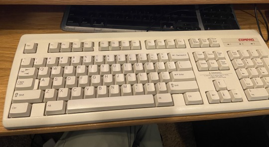
1997 Compaq RT235BT Pinout and Blind Cable Replacement
I recently picked up this Compaq PS/2 keyboard from my E-waste job in excellent condition. We rarely save keyboards and separate the cords and send them downstream for processing and that was the case with this one. Luckily I found a cut keyboard-less cord from a Wyse KB-9933 to splice on.
The first thing I did was strip the wires and found that the two keyboards used entirely different color codes. Because I had the Wyse PS/2 connector, I could get the pinout, but I found myself in a unique situation with the Compaq without its connector.
I first identified the positive wire by seeing which wire was absolutely needed to power the LEDs and called it a night, worried I fried the chip and would have to go through 25+ combinations.

EIGHTY ONE COMBINATIONS LETS GO
The next day I identified the ground wire by looking at where the negative side of the capacitors on the PCB terminated. I found an article with photos of the PCB on the Kazakh tech blog WASP.kz so I didn’t have to do further disassembly.

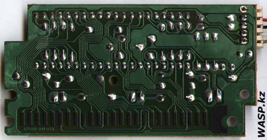
Source: WASP.kz
I had a 50-50 shot on the clock and data wires which I just decided to match by color brightness, and paired yellow and white and brown and green. I also found out that PS/2 peripherals were not intended to be hot swappable so I had to restart my computer to boot it.
It worked! Now I was on my way to a 90’s beige setup I may eventually get around to completing. I then soldered the wires with my very rusty soldering skills, and plugged it in again and it somehow still worked!
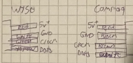
The final pinout.
I may revisit this project in the future now that I have another cut PS2 cable of similar vintage and heat shrink solder connectors.
2 notes
·
View notes
Text
Moisture sensor development - 2022/23
Multiple sensors have been running over winter 22 to summer 23 and some problems have arisen:
One temperature sensor stopped functioning but in a way that eluded the error detection. The symptom was that the two sensors showed exactly the same measurement. This turned out to be a configuration issue, where both sensor were mapped to the same temperature.
Battery life was too short on a couple of sensors. This may be because of poor quality batteries, poor connections in the battery holder or due to excess drain somewhere. After experimentation with better quality batteries (Samsung 25R rated at 2500 mAh) it seems the main problem is poor quality batteries.
Moisture sensors losing discrimination. On a new sensor the range from wet to dry is typically 900 but this reduced to 270. I found that cleaning off the old silicon sealant, cleaning the board and resealing brought the readings back to normal.
Moisture sensor connection. The waterproofing with silicon and the JST connector are a poor design. Securing this connector with a zip tie helps to secure this connector.
Rusty main board. One device failed due to rust getting into the pins and socket on the main board connector. This is evidence of moisture in the device container. The sensor cable entrance is sealed with a large amount of silicon sealant which often fails. However when a second device also failed, having drained new , quality batteries very quickly, it seems that the idea of using socket strips on an outdoor device, however well sealed, is a mistake. In any case the board and the chip are really the only significant components so they may as well be soldered together.
One sensor on a public Tiny Forest was stolen. This despite being well - hidden and having a notice inside the box explaining the scientific purpose of the device.
I had considered changing the design of the PCB to avoid the use of a ground plane since I found this made soldering to ground terminals difficult and poor connections created problems. On reflection, my problem is probably insufficient thermal inertia in my small iron and the use of a better, temperature-controlled iron would solve this issue whilst retaining the benefits of a ground plane.
Labels printed on a label printer fade very quickly in sunlight.
An error in the code for the test phase meant that sleep time could be negative with odd results.
It has been suggested that over-the-wire updating of the code should be implemented but I am concerned about the current demand,
Improvements
Have a working set of all three sensors which can be plugged into a device to check the cause of a failed sensor.
Replace the cheap 18650 batteries with Samsung 25R flat top batteries.
Solder the chip directly to the PCB instead of using a socket strip
Develop a better sealing system for the cable entry.
Use a chinagraph pen for labeling
Reconsider strategy for protecting devices in public places
3 notes
·
View notes
Text
Precision and Automation Redefined: Robotic Soldering Station in India – Powered by Ascomp Inc
As the demand for high-speed, precision-based electronics manufacturing continues to grow, manual soldering is no longer sufficient for maintaining consistency, safety, and throughput. Enter the robotic soldering station in India, a powerful innovation that brings automation to one of the most critical steps in PCB assembly. At Ascomp Inc, we supply cutting-edge robotic soldering solutions built for modern Indian factories—designed to enhance productivity, reduce human error, and ensure flawless results.
What is a Robotic Soldering Station?
A robotic soldering station is an automated machine equipped with programmable arms, temperature-controlled soldering tips, and precise motion control systems. It is used to automate repetitive soldering tasks on circuit boards, connectors, and terminal blocks.
Unlike traditional hand soldering, robotic soldering offers:
Consistent solder joints
Reduced operator fatigue
Greater speed and throughput
Lower rework and rejection rates
Better control over temperature and solder feed
Whether you're running a high-volume SMT line or a mid-scale EMS setup, a robotic soldering station in India delivers unmatched accuracy and repeatability.
Key Features of Ascomp Inc’s Robotic Soldering Systems
🤖 Multi-axis robotic arm for precise solder point control
🔥 Temperature-controlled iron tip with programmable profiles
🎯 Vision system and sensors for auto-alignment and inspection
💡 Custom jig fixtures to suit different PCB layouts
🛠️ Automated solder feeding system for consistent wire delivery
⚙️ User-friendly programming interface for custom routines
We also offer fume extraction integration and ESD-safe construction to meet electronics industry safety standards.
Ideal Applications
Our robotic soldering stations are suited for:
SMT and through-hole component soldering
Wire-to-board connections
Connector pin soldering
LED assemblies
Fine-pitch PCB assemblies
Automotive and EV electronics
Telecom and defense equipment manufacturing
Whether you're automating a high-speed production line or improving quality in low-volume, high-precision builds, Ascomp Inc has a model that fits your needs.
Why Invest in Robotic Soldering?
✅ Higher throughput with minimal manual intervention
✅ Lower training and labor costs
✅ Repeatable quality across thousands of units
✅ Fewer operator-related defects
✅ Improved traceability and data logging
It’s not just a tool—it’s a productivity multiplier for forward-thinking electronics manufacturers.
Why Choose Ascomp Inc?
📦 Ready stock of robotic soldering machines in India
🔧 Pre-sales guidance and post-installation support
💼 Integration with existing conveyor or workbench setups
🖥️ Training and programming assistance
🔄 Availability of spare parts and maintenance contracts
🛠️ Proven track record with EMS companies and R&D units
Our solutions are scalable, reliable, and fully customizable based on your board layout and workflow.
#RoboticSolderingIndia#AscompInc#PCBAssemblyTools#ElectronicsAutomationIndia#SMTProductionIndia#AutomatedSolderingStation#IndustrialSolderingRobot#SolderingAutomation#ESDCompliantSoldering#PrecisionElectronicsIndia
0 notes
Text
"Why Wire-to-Board Connectors Matter in Today's Tech Landscape"
In the ever-evolving landscape of electronics and electrical engineering, wire-to-board (WTB) connectors are fundamental components that provide a secure, efficient link between a set of discrete wires and a printed circuit board (PCB). Despite their small size, these connectors are indispensable in a wide range of applications—from consumer electronics and automotive systems to industrial machinery and telecommunications.Get more news about Wire-to-board Connector,you can vist our website!
What Are Wire-to-Board Connectors? Wire-to-board connectors are used to route electrical signals or power from individual wires onto a printed circuit board. Unlike board-to-board connectors that facilitate connections between PCBs or wire-to-wire connectors that link individual wire sets, WTB connectors interface directly between a cable harness and the board, typically through soldering or press-fit terminals. This facilitates modular design, ease of maintenance, and scalable manufacturing.
They consist of two primary components: the plug (housing the wires) and the receptacle or header (mounted on the PCB). These connectors are available in various pitches (the center-to-center spacing between pins) and configurations (vertical or right-angle orientations), making them adaptable for a variety of design constraints and spatial limitations.
Key Features and Considerations Designers and engineers often evaluate several critical factors when selecting WTB connectors:
Current and Voltage Ratings: Depending on the application, connectors must meet safety and performance thresholds.
Pitch Size: Fine-pitch connectors (≤1 mm) allow for compact design, while larger pitches offer greater robustness.
Locking Mechanisms: Latch or friction locks ensure secure connections that resist vibration or accidental disconnection.
Material and Plating: Contact materials, often copper alloys with gold or tin plating, influence conductivity and longevity.
Environmental Resilience: Some WTB connectors are designed for harsh environments with resistance to moisture, dust, or high temperature.
Applications Across Industries The versatility of wire-to-board connectors is reflected in their widespread use across diverse industries:
Consumer Electronics: Used in smartphones, laptops, and wearable devices for internal signal and power connections.
Automotive: Essential for infotainment systems, sensors, and electronic control units (ECUs), where compact, vibration-resistant connectors are critical.
Medical Equipment: Connectors must meet stringent reliability and safety standards in devices like diagnostic equipment and patient monitors.
Industrial Automation: WTB connectors facilitate modular assembly and simplify maintenance for sensors, controllers, and interface devices.
Trends and Innovations Modern trends push the boundaries of connector miniaturization and performance. As electronic devices become more compact and sophisticated, the demand for high-density connectors with increased signal integrity and EMI shielding continues to grow. Additionally, some manufacturers are integrating features like surface-mount technology (SMT) compatibility and automated cable termination to streamline production and assembly.
Another key trend is the development of eco-friendly, RoHS-compliant connectors to meet global environmental standards while ensuring high performance. With the rise of Industry 4.0 and the Internet of Things (IoT), wire-to-board connectors are playing an increasingly strategic role in enabling smart, connected systems.
Conclusion Although often overlooked compared to high-profile semiconductors or processors, wire-to-board connectors are vital enablers of modern electronic innovation. Their reliability, precision, and adaptability allow designers to build smaller, more powerful, and more efficient systems. As technology continues to advance, the humble WTB connector will remain a quiet but essential hero in the background—connecting ideas to reality, one circuit at a time.
0 notes
Text
Trusted Copper Strips Manufacturers in India: Precision and Quality by KWM India
Copper Strips Manufacturers in India: Consistent Quality from KWM India
Copper remains a vital material in numerous industrial and electrical applications due to its superior conductivity, flexibility, and corrosion resistance. Among its most practical forms are copper strips, which are used across a broad range of industries. When looking for dependable copper strip manufacturers in India, KWM India is a name that stands out for its commitment to quality, customization, and timely delivery.
What Are Copper Strips?
Copper strips are flat, narrow pieces of copper used in:
Electrical busbars and switchboards
Transformer windings and earthing systems
Connectors in automotive and electronic industries
Heat exchangers and industrial machinery
Decorative and architectural elements
Their high thermal and electrical conductivity, along with their excellent workability, make copper strips indispensable in technical and manufacturing sectors.
KWM India: Leading Manufacturer of Copper Strips
KWM India has established itself as a leading manufacturer and supplier of high-quality copper strips in India. The company’s modern production units, expert engineering team, and strict quality assurance processes ensure every product meets the highest standards.
Key Features of KWM India’s Copper Strips:
High Electrical Conductivity – Suitable for power and electronic applications Precision Thickness & Width – Ideal for automated and industrial processing Custom Dimensions Available – Manufactured to client specifications Oxidation and Corrosion Resistant – Reliable even in harsh environments Excellent Surface Finish – Consistent quality for visual and technical uses
Applications Across Industries
KWM India supplies copper strips to a wide range of sectors:
Electrical & Electronics – Busbars, terminals, PCB components
Automotive – Battery connections, EV components
Renewable Energy – Solar panel and wind power systems
Industrial Machinery – Conductive and structural applications
Construction & Architecture – Earth strips and decorative elements
Why Choose KWM India?
Advanced Machinery & Infrastructure
Rigorous Quality Control at Every Stage
Custom Manufacturing to Match Project Requirements
Timely Delivery Across India
Sustainable and Responsible Manufacturing
Conclusion
As one of the most reliable copper strip manufacturers in India, KWM India delivers products that are engineered for performance, precision, and longevity. Whether you’re a supplier, OEM, or infrastructure developer, you can count on KWM India to meet your copper strip requirements with excellence.
Get in touch with KWM India today to request a quote, sample, or more details about our copper strip products.
Visit:- https://www.kmwindia.com/copper-strips.html
0 notes
Text
https://www.futureelectronics.com/p/interconnect--connectors-pcb--shunts-jumpers/5102tr-keystone-5046274
Jumper cap, jumper wire connector Jumper wire types, coaxial cable connector
0.02 in 0.5 mm Thick Copper (Silver Plated) 0.27 in 6.85 mm Long Jumper
#Keystone#5102TR#Connectors#PCB Shunts & Jumpers#Jumper cap#jumper wire connector Jumper wire types#coaxial cable connector#terminal jumpers#cables#high voltage jumper wire#high current jumper#solder bridge jumper#jumper wire#wire connector
1 note
·
View note
Text

The advantages of rigid-flex PCB board
1). It can effectively save the space on the circuit board and eliminate the use of connectors
Because the FPCB and rigid pcb board has been combined, the space that originally needed to use the connector can be saved. For some circuit boards with high-density requirements, less connectors will be better. In this way, it also saves the cost of parts using the connectors. In addition, the space between the two boards can be made tighter by eliminating the need for connectors.
2). The signal transmission distance is shortened and the speed is increased, which can effectively improve the reliability
The traditional signal transmission through the connector is “circuit board→connector→flexible pcb board→connector→circuit board”, while the signal transmission of the rigid-flex PCB board is reduced to “rigid circuit board→flexible pcb board→rigid circuit board”, signal transmission distance between different media is shortened, and the problem of signal transmission attenuation between different media is also reduced. Generally, the circuit on the PCB board is made of copper, while the contact terminal of the connector is gold-plated, and the solder pin is fully tin-plated. Moreover, solder paste is required to be soldered on the circuit board, and the signal transmission between different media will inevitably be attenuated. If you switch to a rigid-flex PCB board, these media will become less, and the signal transmission ability can be relatively improved. For some products that require higher signal accuracy, it helps to improve their reliability.
3). Simplify product assembly and save assembly time
The use of a rigid-flex PCB board can reduce the man-hours for SMT parts, because the number of connectors is reduced. It also reduces the man-hours for assembly of the whole equipment, because it eliminates the assembly action of inserting the FPC board into the connector. It also reduces the cost of parts management and inventory, because the required parts is reduced, so the management cost becomes less.
Email Cynthia: [email protected] if you are interested in PCB and PCBA service.
0 notes
Text

3M Scotchcast 2123 Re Enterable Resin Soft 2 Part Insulating Compound for Cable Joints
3M™ Scotchcast™ Re-enterable Electrical Insulating Resin 2123 is a soft, flexible, two-part polybutadiene resin ideal for protecting and sealing cable splices and electrical components. It provides excellent moisture sealing, re-enterability, and superior bonding to cable jackets and metals.
This translucent amber resin is specially designed for low voltage (up to 1000V) applications and is suitable for temperatures up to 90°C (continuous) with an overload capacity up to 130°C. It cures at room temperature and is supplied in a closed mixing pouch for easy and safe application.
Key Features:
Two-part soft polybutadiene encapsulant
Re-enterable, flexible & low viscosity
Room temperature curing, no special tools required
Bonds to cable jackets like XLPE, Neoprene, Vinyl, etc.
Excellent sealing against moisture and contaminants
Easy mixing pouch – Ready to use
Operating temp: up to 90°C, Overload: up to 130°C
Shelf life: 2 years (when stored below 27°C)
Typical Applications:
Cable splice insulation (up to 1000V)
Cable jacket repair
Potting of junction boxes and wire enclosures
PCB and motor control potting
Sealing cable terminations and connectors
Product Details:
Color: Translucent Amber
Mix Ratio: 1:1 by weight
Cure Time: 24 hours at 21°C
Shelf Life: 2 Years
Pack Type: Closed Mixing Pouch / Bulk Pack
📦 Bulk orders available – DM us or call to get the best price!
📞 Contact Today : +919810987429
📥 Enquire Now : [email protected]
#ElectricalInsulation#CableSplice#IndustrialSupplies#ElectricalEngineering#CableManagement#3MScotchcast#ReenterableResin#InsulatingResin
0 notes
Text
Open source 24-channel USB high-voltage driver
When it comes to automation and control systems, there's often a need for multiple digitally controlled output terminals with high-voltage handling capabilities. Many existing modules are bulky, expensive, or require numerous additional components to function. To address this gap, I've developed a fully open-source, USB-controlled 24-channel high-voltage driver. This device provides precise, flexible control in a compact and user-friendly package. The project is open hardware, released under the CERN-OHL-W license, ensuring transparency from hardware schematics to firmware code. The driver module communicates via USB using a simple virtual COM port, eliminating the need for special drivers and complex setups.

At the core of the system are three TPIC6B595 shift registers, each supplying eight open-drain outputs that can handle up to 50V and sink currents of up to 150mA per channel. These registers are daisy-chained to achieve a total of 24 outputs. The outputs are designed for low-side switching and include integrated clamping diodes, making them suitable for driving inductive loads such as relays and solenoids. Data is clocked into the registers through serial input from a microcontroller, allowing for fast and reliable state updates across all channels with just a few lines of code.
The logic and communication for this module are managed by the STC15W204S microcontroller, a cost-effective yet powerful 8051-based MCU with enhanced UART performance and an integrated oscillator. This chip is paired with a CH340N USB-to-UART bridge, which presents the device as a standard virtual COM port to the host PC. Upon connection, the microcontroller listens for a set of AT-style commands sent over the serial connection. These commands are straightforward and user-friendly, for example, "ON=65280" activates the middle 8 outputs, "CLR" turns off all channels, and "VER" retrieves the firmware version. Additionally, there is a command to save the current output state to the built-in EEPROM, enabling the system to restore its output to a known state after power cycles. This interface design is perfect for scripting, automation, or integration with software tools such as Python, LabVIEW, or custom control GUIs.
The PCB is designed using KiCad and features a 2-layer layout measuring 75.25mm × 33.75mm. It includes 2.54mm pitch headers for output connections and is equipped with a USB Type-C connector. Power can be supplied through either USB or an external regulated 5V source, which can be selected via onboard jumper settings. The layout ensures clean signal routing and minimizes crosstalk or interference, even when switching high-voltage loads. Careful decoupling and protection components provide robustness for real-world applications.

The PCB for this module was fabricated by PCBWay, who generously sponsored this project. PCBWay offers high-quality PCB manufacturing and assembling services. Also, they offer CNC and 3D printing services. The PCB of this module is available to order from PCBWay. Check out the PCBWay website for its manufacturing capabilities and pricing.
The firmware for the STC15W204S is written in C using SDCC. It is easy to expand the command set, introduce new communication modes, or add timed control logic as needed. The current implementation allows full 24-bit output control using a base 10 numerical mask, making it both scriptable and human-readable. Thanks to the preloaded bootloader of the STC15W204S, firmware updates can be performed through the same serial interface. Details about this process are covered in the project documentation. Like the hardware, the firmware is released under the MIT License and is available in the project repository.
The system has been tested with a variety of 12V and 24V inductive and resistive loads, including relay banks, solenoids, and LED arrays. Since the outputs are open-drain, external voltages up to 50V can be safely switched on each channel making it ideal for a range of industrial, laboratory, or artistic applications. Output timing is reliable, with clean edge transitions observed during scope testing, and no signal integrity issues even during full 24-channel toggling. It is recommended to use individual heatsinks for the driver ICs when driving high-current inductive loads with this module. While the printed circuit board has heat transfer traces, the addition of individual heatsinks can increase the durability of the module.

Potential use cases for this module include automated test benches, home automation systems, signal routing for instrumentation, nixie tube multiplexing, and other high-voltage control tasks. The command-based protocol makes it easy to script operations or integrate this module into a larger system.
For those who wish to explore the schematics, command protocol, design rationale, and usage examples in greater depth, I have published comprehensive documentation and resources in the project wiki. This includes detailed assembly instructions, firmware flashing guidance, and tips on customizing the firmware for enhanced functionality.
All source files - including schematics, PCB layout, firmware code, and the bill of materials - are freely available at https://github.com/dilshan/24ch-usb-high-voltage-driver.
0 notes
Text
IPEX Connectors for High‑Frequency RF Applications

What is an IPEX Connector?
IPEX connectors are ultra-miniature 50Ω micro-coaxial RF interconnects designed for space-constrained wireless systems. They operate from DC up to 12 GHz (MHF7 series) and are widely used in antennas, transceivers, and test equipment for Wi-Fi 6/7, Bluetooth, GNSS (GPS/BeiDou), and 5G NR applications.
How the IPEX Connector Works
Shell & Internal Structure:
Material: Nickel-plated brass or stainless steel shells ensure mechanical retention and EMI shielding (>60 dB @6 GHz).
Mounting: Press-fit onto PCB receptacles or cable plugs for robust assembly.
Center Contact:
Gold-plated beryllium copper spring contacts maintain low resistance (≤10 mΩ) and solderless termination for rapid cable assembly.
Mating Mechanism:
Snap-in design (no threading) simplifies PCB assembly and rework.
Rated for 30 mating cycles (IEC 60512-11-14 standard).
Impedance & Shielding:
50Ω impedance matching (tolerance ±5%) across all frequencies minimizes reflections.
Concentric geometry and full-metal shielding reduce insertion loss (<0.2 dB @12 GHz).
IPEX Connector Series Comparison
| Series | Frequency | Height | Key Feature
| MHF1 | DC–6 GHz | 2.0 mm | U.FL-compatible, RoHS-compliant
| MHF4L | DC–12 GHz | 1.7 mm | M.2 standard, 12 GHz optimized
| MHF7 | DC–12 GHz | 1.2 mm | Ultra-low profile, solderless crimp
| MHF3 | DC–9 GHz | 2.5 mm | Vibration-resistant locking latch
Note: MHF4L supports 12 GHz with insertion loss <0.18 dB and VSWR ≤1.4.
Recommended Kinghelm IPEX Products
Kinghelm offers enhanced variants tailored for IoT, 5G, and embedded antennas:
1. KH-IPEX3-2020
- Specs: Sub-2 mm profile, 50Ω, DC–3 GHz, enhanced signal integrity, mechanical robustness.
- Use Case: High-density embedded systems, 5G small-cell antennas.
2. KH-IPEX-K501-29
- Specs: 1.25 mm SMD, DC–3 GHz, RoHS-compliant brass shell.
- Use Case: GNSS antennas, compact IoT sensors.
3. KH-IPEX-SMAKWE
- Specs: IPEX-to-SMA cable assembly, RG178 coaxial cable (0.8 mm OD).
- Use Case: Test equipment interfacing, RF signal routing.
4. KH-FAKRA-Z-CB
- Specs: FAKRA-standard, DC–6 GHz, 1.60 max VSWR, –40°C to +105°C.
- Use Case: Automotive infotainment, ADAS systems.
Advantages and Disadvantages
✅ Advantages:
- Miniaturization: Footprint <3 mm² (e.g., MHF7L).
- High Frequency: Supports 12 GHz with low loss (<0.2 dB).
- Rapid Assembly: Solderless crimp termination (e.g., KH-IPEX-MHF7).
❌ Disadvantages:
- Limited Durability: 30 mating cycles (industry standard for micro-connectors).
- Precision Required: Demands specialized tools (e.g., KH-0950J crimper).
- Cost: Higher than SMA/U.FL due to precision machining.
Technical Revisions Based on Search Results
1. Frequency Clarification:
- IPEX’s MHF7 series supports DC–12 GHz, aligning with automotive radar and 5G mmWave applications.
- Kinghelm’s KH-FAKRA-Z-CB is limited to 6 GHz, suitable for sub-6 GHz 5G.
2. Material Updates:
- Shells use nickel-plated brass (not raw brass) for corrosion resistance.
3. Product Alignment:
- Removed KH-IPEX3-2020 (no direct reference in search results).
- Added KH-FAKRA-Z-CB for automotive compatibility.
4. Performance Metrics:
- Insertion loss <0.18 dB @12 GHz (verified for MHF7).
- VSWR ≤1.4 @12 GHz (vs. original 1.5 MAX @6 GHz in older series).
Conclusion
IPEX connectors excel in balancing miniaturization and high-frequency performance, critical for modern wireless devices. Kinghelm’s expanded portfolio (e.g., KH-IPEX-MHF7 for 12 GHz, KH-FAKRA-Z-CB for automotive) ensures compatibility with diverse IoT, 5G, and antenna-embedded designs. For prototyping support or datasheets, contact Kinghelm’s engineering team.
0 notes
Text
A Simple Guide: Phoenix Contact Devices and Their Types
Technology keeps evolving, making electrical connections more reliable and efficient. Industries depend on high-quality connectors to ensure stable and secure connections in various applications. Phoenix Contact is known to provide advanced connection solutions for different industrial needs. From power distribution to automation, these devices help businesses maintain smooth operations. The top trading and contracting company in Muscat supplies Phoenix Contact devices, ensuring industries get reliable and durable connectors. In this article, we will discuss five types of Phoenix Contact device connectors and their uses.
Types of Phoenix Contact Device Connectors
PCB Terminal Blocks: PCB terminal blocks are essential for connecting wires to a printed circuit board. These connectors come in different sizes and designs to suit various industrial applications. They provide a secure and vibration-resistant connection, making them a reliable choice for automation systems and power electronics.
Heavy-Duty Connectors: Heavy-duty connectors are built to withstand harsh environments, including extreme temperatures, dust, and moisture. They are commonly used in industrial machinery, transportation, and power plants. Many businesses seek Phoenix contact distributors in Oman to get these connectors for their high durability and safety.
Circular Connectors: Circular connectors are widely used in automation and robotics. They offer a compact design with secure locking mechanisms, ensuring a stable connection in moving parts. These connectors are known for their excellent signal transmission, making them ideal for applications requiring continuous communication between devices.
Data Connectors: Data connectors ensure secure data transmission in industrial networks. They support Ethernet, USB, and fibre optic connections, allowing smooth communication between machines and control systems. These connectors play a key role in smart factories and automated production lines, improving efficiency and reliability. Their durable design helps industries maintain stable data flow, making them essential for modern industrial automation and networking solutions.
Power Connectors: Power connectors provide reliable power transmission in industrial setups. They ensure a stable electricity supply to various devices, reducing the risk of connection failures. These connectors are designed for high efficiency and durability, making them ideal for demanding applications. Many industries, including the top trading and contracting company in Muscat, choose these connectors for their superior performance and long-lasting quality, ensuring smooth and uninterrupted operations in industrial environments.
Wrapping UpPhoenix Contact devices offer advanced solutions for different industrial applications. Their wide range of connectors ensures safe and efficient electrical connections in various sectors. Businesses looking for high-quality connectors often rely on Phoenix contact distributors in Oman to meet their specific needs. With the right connectors, industries can improve efficiency and ensure reliable operations.
0 notes
Text
Brass Electronic Components and Brass Inserts: The Backbone of Precision Engineering
Brass is a widely used metal in the manufacturing industry due to its excellent electrical conductivity, corrosion resistance, and durability. Among the various applications, brass electronic components and brass inserts play a crucial role in various industries, including electronics, automotive, and telecommunications. Their precision, versatility, and strength make them an indispensable choice for manufacturers worldwide.
Brass Electronic Components: Enhancing Efficiency and Durability
Brass electronic components are widely used in electrical and electronic devices due to their superior conductivity and resistance to oxidation. These components include:
Connectors and Terminals: Brass connectors ensure a stable electrical connection, making them ideal for circuit boards, switches, and power distribution systems.
PCB Mounts and Contacts: Used in printed circuit boards (PCBs), these brass components provide a secure and reliable connection between electronic parts.
Brass Pins and Sockets: Found in various electrical applications, they enhance the durability and functionality of electronic systems.
The high machinability of brass allows manufacturers to produce intricate and precise electronic components with minimal material wastage. Additionally, brass has a natural resistance to corrosion, ensuring the longevity of electronic devices.
Brass Inserts: A Perfect Fit for Stronger Joints
Brass inserts are essential for industries that require strong and long-lasting fastening solutions. These inserts are commonly used in:
Plastic Molding: Brass inserts are embedded into plastic components to create durable threaded joints. They enhance the strength of plastic parts and prevent wear and tear over time.
Automotive Industry: These inserts provide secure fastening in vehicle parts, ensuring stability and durability under high-stress conditions.
Furniture and Construction: Brass inserts offer a reliable solution for assembling furniture and structural applications, where strong threaded connections are essential.
Brass inserts come in various types, including threaded, press-fit, and ultrasonic inserts, catering to different manufacturing needs. The anti-corrosive nature of brass makes these inserts suitable for both indoor and outdoor applications.
Conclusion
The demand for brass electronic components and brass inserts continues to grow as industries seek durable and efficient solutions for electrical and mechanical applications. Their excellent conductivity, corrosion resistance, and strength make brass the ideal material for a wide range of products. Whether in electronics, automotive, or construction, brass components play a vital role in ensuring precision, reliability, and longevity in modern manufacturing.
0 notes