#PinMux
Explore tagged Tumblr posts
Visit Tumblr Blog
Explore Tumblr blogs with no restrictions, modern design and the best experience.
Last Seen Tumblr Blogs


Fun Fact
69% of Tumblr users are millennials.
Text
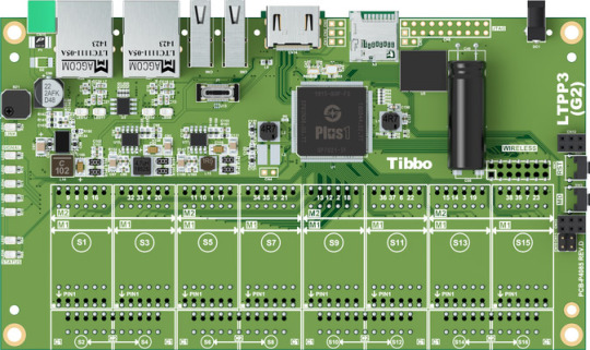
Tibbo's Remote IO Controllers Offer Unmatched Flexibility
Also in this issue:
CODY: Develop Complete Applications Without Any Coding
PinMux Wrapper Gains I²C Support

Remote I/O devices are well-established in the industrial world. By supporting popular communications protocols such as Modbus, they give other equipment and control systems such as SCADA access to remote inputs and outputs. Tibbo's Remote IO (RIO) controllers offer an important advantage over the competition. Built on our Tibbo Project System (TPS) platform, our RIO devices are tremendously flexible because all of their I/O and sensing capabilities come from the installed Tibbit modules. While other vendors offer long lists of remote I/O devices in various fixed configurations, we let you pick and choose just the features that you require for each particular project. Need a certain I/O function? Install the right Tibbit. Have no use for something? Leave it out. Since all this flexibility can be intimidating to novice users, we're rolling out a number of standard starter configurations. These devices are ready to be deployed or can serve as the starting point for your own tailored controller. RIO controllers run our open-source Remote IO app, which features an advanced, intuitive UI that simplifies controller configuration. The interface displays the actual layout of the device and lists the Modbus registers associated with each I/O line or Tibbit function. To simplify the deployment in the field, our RIO controllers optionally allow the configuration of basic parameters from your smartphone over a BLE connection.
Explore Tibbo Remote IO
---
CODY: Develop Complete Applications Without Any Coding
youtube
In our previous CODY tutorial, we demonstrated how to configure an RS485 port (Tibbit #05) on a TPP2(G2) to work with Tibbo's Bus Probe #03 (light sensor) — all in a matter of minutes! This month, we show you how to take that project over the finish line and turn it into a functional application without writing any code. How do we accomplish such a magical feat? With AppBlocks, the last link that turns CODY into a truly no-code development tool. Now you can spend less time on developing code and focus more on creating and deploying solutions. The AppBlocks feature provides an intuitive visual development environment. In this environment, all supported software modules are represented by blocks, which you drag onto and interconnect inside the project canvas. For many usage scenarios, CODY is now capable of producing fully functional, deployable applications. We invite you to see for yourself the truly revolutionary nature of AppBlocks. As the development is ongoing — with new functionality and support for more features being added regularly — we welcome any feedback regarding your experience. P.S. Feel free to contact us for a personalized, complimentary guided tour of CODY.
Try AppBlocks Now
---
PinMux Wrapper Gains I²C Support
As part of the ongoing development of Tibbo's Ubuntu-derived distribution, we've updated the Python wrapper for PinMux to support I²C communications. The wrapper now allows you to dynamically map the I/O lines of the Plus1 SoC to I²C peripherals. To demonstrate this functionality, we've added an I²C example using Tibbit #36 (an accelerometer) to our Getting Started guide. This example consists of the sample code and a custom library for this Tibbit, both written in Python. Tibbit #36 was chosen because it is one of our more complicated I²C sensors, which means that your code will probably be simpler than this sample code. Separately, we've also updated the Wi-Fi and Bluetooth configuration scripts included in our distribution's Out-of-Box Experience (OOBE). These new interactive scripts consolidate the functions of several older scripts to make wireless driver installation and configuration truly effortless. Getting the latest versions of the PinMux wrapper and OOBE is as simple as performing an update and upgrade of your installation — also covered in our guide!
Get Started Now
#Tibbo#IoT#IIoT#Industrial Automation#Industry 4.0#low-code#no-code#CODY#development#Linux#Ubuntu#PinMux#Python#I²C#I2C#tutorial#Remote IO#RIO884#Modbus#Youtube
0 notes
Text
Nintendo Switch Kernel Patching and Emulation - Achieving Maximum Modification Flexibility with Minimal Replacement
Ever since shofEL2 was released earlier this year it's been interesting to watch how different custom firmwares have tackled the prospect of modifying Nintendo's firmware for both homebrew and piracy applications, and as someone who hasn't really had much stake in that race I feel like it's interesting to watch how different solutions tackle different problems, but at the same time since I do have a stake in a few places (namely, Smash Bros modding, vulnerability hunting, personal projects) I ended up in a situation where I needed to sort of 'set up camp' with Nintendo's Horizon microkernel and have a comfortable working environment for modification.
Binary Patching is Weird, and Horizon makes it weirder.
Probably the biggest difficulty in Switch development I would say is iteration time, followed by a general difficulty in actually modifying anything; even just booting modified core services (ie filesystem management, service management, spl which talks to the EL0 TrustZone SPL [commonly misnomered as the security processer liaison...?], the boot service which shows boot logos and battery indications, ...) requires, at a minimum, reimplementing Nintendo's package1 implementation which boots TrustZone and patches for TrustZone to disable signatures on those services and kernel. Beyond the core services, modifying executables loaded from eMMC requires either patching Loader, patching FS, reimplementing Loader, or something else.
Unfortunately with binary patching there generally isn't a silver bullet for things, generally speaking the three methods of modifications are userland replacement, userland patching, and kernel patching. The first two are currently used for Atmosphere, but the solution I felt would be the most robust and extensible for the Nintendo Switch was kernel patching. Here's a quick rundown on the pros and cons for each method:
Userland Replacement
- Requires rewriting an entire functionally identical executable - Often not feasible for larger services such as FS - Can easily break between firmware updates, especially if new functionality is added or services split. This makes it difficult to maintain when the OS is in active development. - Added processes can potentially leave detectable differences in execution (different PIDs, different order of init, etc) + Easier to add functionality, since you control all code + Can operate easily on multiple firmwares + Can serve as an open-source reference for closed-source code
Userland Patching
- Adding additional code and functionality can be difficult, since expanding/adding code pages isn't always feasible without good control of Loader - Finding good, searchable signatures can often be difficult - Can easily break between firmware updates, especially if functionality or compilers are tweaked + With good signatures, can withstand firmware updates which add functionality + Often has less maintenance between updates when functionality does change; patching is usually easier than writing new code + Harder to detect unless the application checks itself or others check patched applications
Kernel Patching
- Greater chance of literally anything going wrong (concurrency, cache issues, ...), harder to debug than userland - Minimal (formerly no) tooling for emulating the kernel, vs userland where Mephisto, yuzu, etc can offer assistance - Can easily break between firmware updates, and is more difficult (but not impossible) to develop a one-size-fits-all-versions patch since kernel objects change often - Easier to have adverse performance impacts with syscall hooks + Harder to detect modifications from userland; userland cannot read kernel and checking if kernel has tampered with execution state can be trickier + Updating kernel object structures can take less time than updating several rewritten services, since changes are generally only added/removed fields + Direct access to kernel objects makes more direct alterations easier (permission modification, handle injection, handle object swapping). + Direct access to hardware registers allows for UART printf regardless of initialization state and without IPC + Hooking for specific IPC commands avoids issues with userland functionality changes, and in most cases IPC commands moving to different IDs only disables functionality vs creating an unbootable system.
mooooooo, a barebones Tegra X1 emulator for Horizon
Obviously the largest hangup with kernel patching is debugging, the Switch has RAM to spare (unlike 3DS) and setting up an intercept for userland exceptions isn't impossible to do by trial and error using SMC panics/UART and a lot of patience, but for ease of use and future research I really, really wanted an emulator to experiment with the Switch kernel. I ended up building a quick-n-dirty emulator in Unicorn, and with a few processes it works rather well but it still struggles with loading Nintendo's core processes currently, but for a small and contained test environment (two processes talking to each other and kernel patches watching them), I would say I had reached my goal and it was enough to at least be able to work quickly and sanely on my intercept.
For the most part, the Switch Horizon microkernel doesn't actually use much of the Tegra MMIO; it uses some of the more obvious ARM components like GIC for interrupts, and it also has a large initialization sequence for the memory controller, but as long as interrupts are functional, timers work, MC returns some correct values and SMC return values are all correct, it boots into userland without issue.
I actually found that emulating multiple cores in Unicorn actually isn't all that difficult, provided you're using a compiled language where uc_mem_map_ptr works. Rather than messing with threads, I opted for a round-robin scheduling scheme where I run each Unicorn instance for a set number of instructions, with memory being mapped and unmapped from the running core so that any cached data gets written out before the next core has its turn. A lot of modifications/cherry-picking to Unicorn did have to be made in order to properly support interrupts, certain coprocessor registers (ie core indexes), translation tables (for uc_mem_read/uc_mem_write, vaddr->paddr translation, and just in general there were some odd issues).
Patching Horizon for Syscall MiTM
With a decent environment for modifying kernel, the next issue really just became actually bootstrapping an SVC intercept. Figuring out where exception vectors are located isn't difficult with the emulator handy, but really the issue becomes
1. Extra code has to be loaded and copied by TrustZone, along with kernel 2. New code needs to be placed in a safe location and then given memory mappings 3. Existing code needs to be modified with hooks pointing to the new code
To guide the kernel towards salvation I ended up hooking just before translation table addresses are written into coprocessor registers. This way, the payload can allocate pages and copy code from less-safe soon-to-be-condemned .bss memory for the bulk of the SVC interception code, set up those pages in the translation tables, and then patch the ARM64 SVC handler to actually jump to the new mapping. For ease of development, the mapping is given a constant address along with any hardware registers which it needs to access, as opposed to being randomized like the rest of the kernel.
In the end, patched the kernel executes as follows:
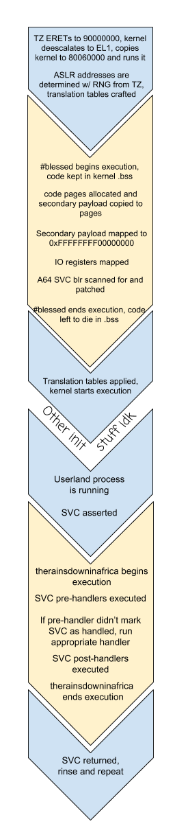
Since hashtagblessed is able to map UART, CAR and PINMUX registers into translation tables, getting communication from the right Joy-Con rail using existing BPMP-based drivers was fairly straightforward, and even without any source code to reference there's a fairly basic driver in TrustZone. Between the transition from emulation to hardware however, I had kept an SMC to print information to the console, but I ultimately ended up using UART even in emulation. On hardware, I got by using UART-B (the right Joy-Con railed) for a while, but had to switch to UART-A (internal UART lines for debugging) due to GPIO issues once HOS tried to initialize Joy-Con.
Identifying IPC Packets, Accurate Results With Simple Tools
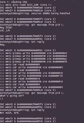
With therainsdowninafrica loaded, hooked in and blessed, the next step is actually being able to identify specific IPC requests sent through svcSendSyncRequest, and doing this requires getting our hands dirty with kernel objects. Userland is able to utilize different kernel objects indirectly through the use of handles and system calls. Each KProcess has a handle table which maps handles to the underlying object structures, so translating handles to KObjects is simply a matter of checking the table for a given handle passed to a syscall. To access the current KProcess object which has the handle table, we can use the per-core context stored in register X18 as of 5.0.0 (prior to Horizon implementing ASLR, it was stored in a hardcoded address per-CPU) and the handle table can be accessed through the current KProcess object. Printf debugging was extremely useful while figuring out exactly how KProcess has its fields laid out since the structure changed slightly between versions, and with a bit of reversing added in it's not particularly difficult to figure out exactly where the KProcessHandleTable is at how handles are translated into objects.
Probably the most useful fields in KProcess/KThread, in our case, are the process name and title ID, the handle table, and the active thread's local storage, where all IPC packets are read from and written to. To give a quick overview on how Switch IPC generally works, services are able to register a named port to wait for communications on which can be connected to by other processes via svcConnectToNamedPort. In practice, Nintendo only uses globally-accessible named ports for their service manager, `sm:`. On a successful call to svcConnectToNamedPort, processes recieve a KClientSession handle for sm: which allows those processes to send IPC requests to the service manager to either register/unregister/connect to 'private' named ports managed by the service manager, with sm checking whether the requesting process actually has access to said service.
From a practicality standpoint, since so much communication relies on IPC the most obvious mechanism to establish is a system for hooking requests going into specific named ports, both globally accessible ones such as sm: and private ones provided by sm itself. This kinda leads into why it's important to have access to the underlying KClientSession objects as opposed to trying to track handles; mapping out exactly which KProcess' handles go to what, while also tracking where handles might be copied and moved to is an almost impossible task, however mapping specific KClientSessions to specific handlers avoids the handle copying/moving issue since the KClientSession object pointer does not change in those cases.
Additionally, many interfaces aren't actually accessible from either svcConnectToNamedPort nor sm, as is the case with fsp-srv which gives out IFileSystem handles for different storage mediums. However, by providing a generic means for mapping KClientSession objects to specific intercept handlers, you can set up a chain of handlers registering handlers. For example, intercepting a specific eMMC partition's IFile's commands would involve setting up a handler for the sm global port, and then from that handler setting up a handler for any returned fsp-srv handles, and then from the fsp-srv handler checking for the OpenBisFileSystem command for a specific partition to hook the IFileSystem to a handler, which can have its OpenFile command hooked to hook any outgoing IFile handles to a specific handler for IFiles from that eMMC partition. From that point all incoming and outgoing data from that IFile's KClientSession can be modified and tweaked.
Finally, in order to prevent issues with KProcess handle tables being exhausted, Nintendo provided virtual handle system implemented in userland for services which manage large amounts of sessions. Effectively, a central KClientSession is able to give out multiple virtual handles (with virtual handles given out by virtual interfaces) only accessible through that KClientSession handle. As such, a process can take a service such as fsp-srv and with a single handle can manage hundreds of virtual interfaces and sub-interfaces, easing handle table pressure on both the client and server ends. These handles can be accommodated for by watching for KClientSession->virtual handle conversion, and then keeping mappings for KClientSession-virtual ID pairs. And again, since copied/moved KClientSessions keep their same pointer, in the event that somehow the central handle and a bunch of domain IDs were copied to another process, they would still function correctly.
Tying it All Together
Let's take a look at what it would take to boot homebrew via hbloader utilizing only SVC interception. The key interface of interest is fsp-ldr, which offers command 0 OpenCodeFileSystem taking a TID argument and an NCA path. From a userland replacement standpoint, booting homebrew involves redirecting the returned IFileSystem to be one from the SD card rather than one from fsp-ldr, since Loader (the process accessing fsp-ldr) doesn't really do any authentication on NSOs/NPDMs, only FS does. From a kernel standpoint, we just need to watch for an IPC packet sent to fsp-ldr for that command, hook the resulting handle, and then for each OpenFile request check if an SD card file can better override it. From there, swap handles and now Loader is reading from an IFile on the SD card rather than an NCA.
Taking a few steps back, there's obviously a few things to keep in mind: Loader never actually accesses the SD card, in fact it doesn't even ask for a fsp-srv handle. Since it is a builtin service it has permissions for everything, but the issue still remains of actually making sure handles can be gotten and swapped in. As it turns out, however, calling SVC handlers from SVCs is more than possible, so if Loader sends a request to sm asking for fsp-ldr, we can send out a request for fsp-srv, initialize it, and then send out the original request without Loader even knowing.
Interestingly, the first thing Loader does with its fsp-ldr handle is it converts it into a virtual domain handle, so that all OpenCodeFileSystem handles are virtual handles. This does make working with it a little more tricky since the code filesystem and code files all operate under the same KClientSession object, but it was an issue which needed resolving anyhow. For SD card IFile sessions, it also means that we have to convert them to virtual handles and then swap both the file KClientSession handle and the file virtual handle ID, while also watching for their virtual ID to close so that we can close our handles at the same time and avoid leakage.
A few other tricks are required to properly emulate the SD redirection experience: swapping in handles isn't the only concern, it's also important to ensure that if the SD card *doesn't* have a file then that error should be returned instead, and if the SD card has a file which doesn't exist in the original IFileSystem, we still need a file handle to replace. To accomodate for this, the original FileOpen request is altered to always open "/main" and if the SD card errors, that virtual handle is closed, and otherwise the SD handles are swapped in.
The end result is, of course, the homebrew launcher being accessible off boot from the album applet:
youtube
Other Potential Thoughts for Kernel Stuff
* Process patching is as easy as hooking svcUnmapProcessMemory and patching the memory before it's unmapped from Loader. Same goes for NROs but with different SVCs, all .text ultimately passes through kernel. * Reply spoofing. IPC requests can simply return without ever calling the SVC, by having kernel write in a reply it wants the process to see. * SVC additions. I'm not personally a fan of this because it starts to introduce ABIs specific to the custom firmware, but it's possible. One of the things I'm not personally a fan of with Luma3DS was that they added a bunch of system calls in order to access things which, quite frankly, were better left managed in kernel. The kernel patches for fs_mitm also violate this. Userland processes shouldn't be messing with handle information and translation tables, i m o. That's hacky. * Virtual services and handles. Since the intercept is able to spoof anything and everything a userland process knows, it can provide fake handles which can map to a service which lies entirely in kernel space. * IPC augmentation: Since any IPC request can be hooked, it can be possible to insert requests inbetween expected ones. One interesting application might be watching for outgoing HID requests and then, on the fly, translating these requests to the protocol of another controller which also operates using HID. * IPC forwarding: similar to augmentation, packets can be forwarded to a userland process to be better handled. Unfortunately, kernel presents a lot of concurrency issues which can get really weird, especially since calling SVC handlers can schedule more threads that will run through the same code. * As currently implemented, A32 SVCs are not hooked, however this is really more an issue if you want to hook outgoing requests from A32 games like MK8, since services such as Loader will generally only operate in a 64-bit mode.
Source
Horizon emulator, https://github.com/shinyquagsire23/moooooooo
therainsdowninafrica, https://github.com/shinyquagsire23/therainsdowninafrica
2 notes
·
View notes
Text
Who’s Barking? BBB Meets h-nanoGSM. [BeagleBone Black GSM How To]
About this post
Twenty to thirty minutes guide lines about connecting BeagleBone Black with the ITBP h-nanoGSM shield.
Main parts
BeagleBone Black
h-nanoGSM – GSM shield [nano] or
any other ITBP modular modem,
1pcs. one cell LiPo battery [3.7V, > 250mA], or
1pcs super-capacitor bigger than 1F rated for more than 5V and having ERS lower than 250mOhm[we’ve tested SCMT22C505MRBA0 from AVX and PM-5R0H105-1 from POWERSTOR/EATON
Knowledge and skills required
BeagleBone Black previous experience is quite welcome,
some entry level Python and Linux knowledge are required,
soldering
About BeagleBone Black
Folks, finding BBB was a pleasant surprise for me! This BeagleBone Black it is awesome – best SBC ever used by me! One very good BBB presentation can be found here.
About h-nanoGSM shield
nanoGSM shield – became commercially available in 2016, August. It is a quad band GSM only (world wide compatible) + Bluetooth 3.0 nano shield, packed in an compact format 1.25″x1.16″(31.75×29.46mm) and with weight around 8g. Same as his bigger brothers [c-uGSM -dual-SIM GSM only and d-u3G – 3G/GSM engine), it is not only a break-board, but a full shield having powerful features embedded, as: USB support (communication and powering), auto level 2.8V-5V digital interfaces and Lithium Polymer charger integrated.
Some hardware hints
The BBB board it’s really a quite powerful engine embedded in a small format. Having 5 UART ports gave us lot of alternatives for interfacing.
Keep in mind that almost all BBB logic pin have several functions accessible trough the PinMUX [mode0 ==> mode7]. Take a look in following pdfs [very important resources]: BBB P9 pins table [pdf] and BBB P8 pins table [pdf]
In our example, we will use the BBB UART1 for data interfacing with the modem and P9_14[EHRPWM1A], P9_16[EHRPWM1B] and P9_18[I2C1_SDA] as modem control interface [CONTROL].
Prepare your h-nanoGSM shield. Solder the pinheader; see how here. Connect the LiPo battery [take care at polarity!] or the super-capacitor, the antenna to the GSM uFL connector. Insert the SIM card [remove PIN code checking before].
Hardware connections
In the picture bellow you can observe all the needed connections.
3G GSM Beaglebone Black howto
Wiring details revealed, bellow:
Above, the h-nanoGSM shield is powered in the “WITH Lithium Polymer” configuration [powered from 5V], but using one 1F super-capacitor instead the LiPo battery [LiPo battery can be used as well]. IMPORTANT:
In our tests, the BBB was powered from the USB. In this case the h-nanoGSM powering was made connecting the BBB SYS_5V with the modem Vin[5V] pin!
Anyway, the BBB recommended powering powering option is via the 5V barrel connector. In this case, we recommend to you to power the modem from the BBB VDD_5V [wire the BBB VDD_5V with the modem Vin[5V] pin].
For other h-nanoGSM shield [or other ITBP modular modems] powering options, read c-uGSM, h-nanoGSM and d-u3G how to start.
Let’s do the magic [Software]
SOFTWARE ASSUMPTIONS
The real target it is to prepare the BeagleBone Black to be compatible with our RPI support files for h-nanoGSM[code examples] and with the PPP examples, making as little changes as possible.
BBB Debian distribution is used in this how to. We assume you will start from a out of the box BBB [if you used your BBB before, some steps may be skipped].
BBB SETUP TASKS
Connect the BBB to the USB. Download the BBB USB driver from http://ift.tt/21fY192. Follow the instructions found on that page and install the USB driver. Connect to the BBB using SSH service [initial username is root, no password].
DEBIAN SETUP [MAINLY BBB PORTS CONFIGURATION, BUT GATHERING SOME PACKAGES TOO]
a. Connect the BBB ethernet port to your LAN. Check the connectivity to the internet. Enter following commands to the shell: apt-get update apt-get install python-serial and, optional: apt-get install mc
b. Using your preferred editor [I like mcedit, this is the reason I’ve installed the mc package, but you may use vi, vim…] edit the /etc/rc.local file:
mcedit /etc/rc.local
and insert following lines at the bottom, but before exit 0:
/etc/rc.config-itbp-modem > /dev/null 2>&1
Save.
c. Copy the following script as /etc/rc.config-itbp-modem [right click & save as]
Make it executable:
chmod 777 /etc/rc.config-itbp-modem
We are almost there…this was the Linux part. Just reboot your BBB [shutdown now -r or reboot will do this job].
PYTHON ITBP MODEM AND PPP SUPPORT FILES
a. Keep in mind that Python ITBP modem and PPP support files was written to compatible with the RPI and Debian distribution. There are three major differences when porting the code to the BBB [Debian]:
a1. The serial port names, /dev/ttyAMA0 for the RPI and /dev/ttyO1 for the BBB [we assumed that UART1 will be used]. We will address this later.
a2. The RPI.GPIO python class it is not present and compatible with BBB python. We will address this later.
a3. The BBB port addressing it is different from the RPI port addressing under python.
For all a1, a2 and a3 will apply some simple patches, later.
b. Download the h-nanoGSM python and PPP support files from the download page. You will need to register using your name, email address and with the IMEI of your h-nanoGSM [the IMEI can be found on the top of the M66FA chip, or you may find using AT+CIMI command].
c. Decompress the archives. This archives contains, along with other files, the following files: “hnanoGSM1_08_hw_control.py”, “hnanoGSM_Serial_Lib.py” and “globalParVar.py”, related to python modem control and serial communication.
d. Copy following file: ITBP_gpioBBB.py [or, right click & save as] in the very same folder where the “mdmname_ver_hw_control.py” [in this case “hnanoGSM1_08_hw_control.py”] it is located.
e. Fixing a1, a2 and a3 differences:
e1. Edit the “hnanoGSM1_08_hw_control.py” file [mcedit hnanoGSM1_08_hw_control.py] and replace the line 17″: import RPi.GPIO as GPIO with: import ITBP_gpioBBB as GPIO
e2. Edit the “hnanoGSM_Serial_Lib.py” file [mcedit hnanoGSM_Serial_Lib.py] and replace the line 40″: agsm = serial.Serial(“/dev/ttyAMA0”, serialSpeed, timeout=1) with: agsm = serial.Serial(“/dev/ttyO1”, serialSpeed, timeout=1)
e3. Edit the “globalParVar.py” file [mcedit globalParVar.py] and set the “CONTROL interface for the ITBP modular modems” as bellow: RESET = “P9_14” POWER = “P9_16” STATUS = “P9_18”
TEST THE SETUP
You may run any ITBP modem python example file [Eg. python sendSMS.py].
Ready. Enjoy!
VARIANTS. REFERENCES.
You may try the setup using other UART ports as /dev/ttyO2 or /dev/ttyO4, or using other BBB I/O pins for modem CONTROL.
First of all, check the pins are free [config-pin utility can gave you valuable information], but guide after following references: – http://ift.tt/1WuSBIl – http://ift.tt/2bqgY8p – http://ift.tt/1PfPc9F – CAPE, what’s about: http://ift.tt/1iwWcgj – BBB pins definition: http://ift.tt/2rN5pgX – and last, but not least http://ift.tt/KONnny
Keep calm, understand what’s under the BBB blanket and write your own cape [best approach]….and share with us.
TUTORIAL & SOFTWARE ARE PROVIDED WITHOUT ANY WARRANTY!!! USE IT AT YOUR OWN RISK!!!!
Originally published by Dragos Iosub on itbrainpower.net
Related Stories
SMS Alarm System (Magnetic Contacts) Using Arduino and 3G / GSM Shield
“How to”: Modular, Mobile IoT Hardware
RC Speed Controller (ESC) Arduino Library
from RobotShop Blog Feed http://ift.tt/2qLRnhk via IFTTT
0 notes
Text
Join the Tibbo Family!
Are you looking for a new challenge? Maybe you want to hone your skills in multiple disciplines — and get paid doing it. Tibbo is looking for a Test Automation Engineer (TAE) to plan, design, and build sophisticated automated test fixtures and systems that help us test our products.
This role requires PCB and mechanical design talent, as well as programming skills (JavaScript, Python, C++, etc.). Tibbo TAEs work with an assortment of technologies, including image recognition, artificial intelligence (AI), and cloud computing (Microsoft Azure). In addition, you must be willing to work with your hands — solder, assemble, test, iterate.
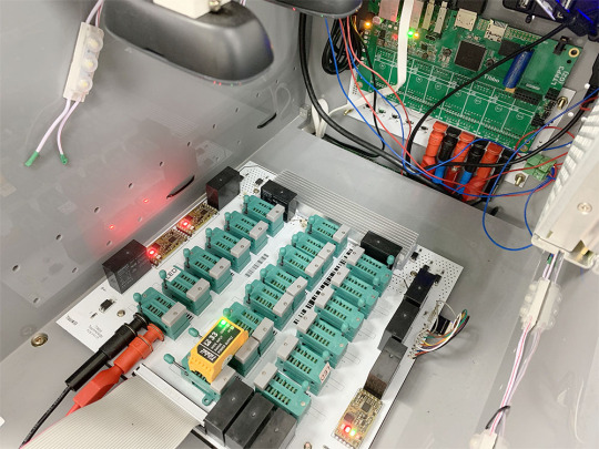
You will be in charge of making automated test equipment such as our Generic Tibbit Test Fixture, which is based on our Size 3 Linux Tibbo Project PCB (LTPP3), Gen. 2. This system leverages the power of image recognition and the flexibility of the Plus1 SoC's PinMux capabilities to identify and test our Tibbits.
This job opening is for our Taipei office — it's not possible to do this job remotely. Foreigners living in Taiwan and residents of other countries are welcome to apply (but you must be willing to relocate to Taiwan). Qualified candidates will be offered three-year contracts with competitive compensation.
0 notes
Text
Ubuntu Update Expands Range of LTPP3(G2) Applications
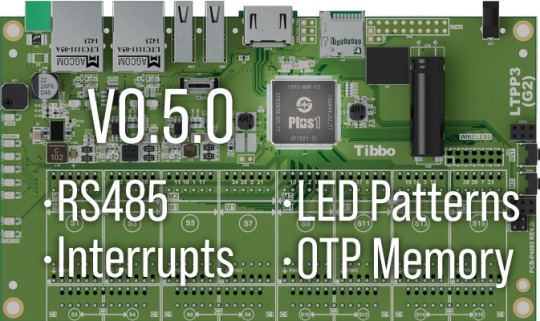
This month, we present you with the latest version of Tibbo's Ubuntu-based distribution for the Size 3 Linux Tibbo Project PCB (LTPP3), Gen. 2. This release introduces several improvements to enable an even wider range of applications and simplify the administration of the LTPP3(G2). Meanwhile, the LTPP3(G2) itself has also received an upgrade, with the latest revision increasing the eMMC storage capacity to 8GB.
Version 0.5.0 of our distro incorporates support for RS485 serial communications in Tibbo's PinMux driver. You can configure this functionality via native C code or a Python library we've prepared for your convenience. To highlight this newly added capability, we've created a sample project that illustrates how easy it is to poll devices such as our RS485 Modbus Sensors.
V0.5.0 also implements support for up to eight user-configurable interrupts, vastly widening the range of possible applications for your projects. Dynamically enable, monitor, and release these interrupts as you need. Our code example demonstrates how simple it is to implement this functionality on the LTPP3(G2).
We've also added LED patterns to provide visual feedback during firmware updates. The green and red status LEDs, as well as the blue LED bar, now provide helpful indicators regarding the status of upgrades. Removing the need to monitor the update process via the serial terminal simplifies the maintenance of headless installations.
Finally, this release includes the driver for the Plus1 CPU's one-time programmable (OTP) memory, allowing your applications to read this special memory.
The latest version of our Ubuntu-based distribution is available on our website. Need to customize your deployment or start from an earlier version? Use our Docker container and build tools to tailor an image specifically for your needs — here's a tutorial video to help you get started.
P.S. Press and hold the MD button for 1 second after the V0.5.0 update is complete (before rebooting) for a special demonstration via the buzzer.
0 notes
Text
Updated Ubuntu Image and Tools Facilitate and Accelerate Development
This month, we present you with the newest version of Tibbo's Ubuntu-derived distribution for our Size 3 Linux Tibbo Project PCB (LTPP3), Gen. 2.
The new release retains all the convenience and functionality of the original image while adding numerous improvements we've made over the past several months. Notable enhancements:
An upgrade to version 5.10 of the Linux kernel brings greater stability and security.
The latest versions of our Out-of-Box-Experience (OOBE) scripts simplify the configuration of the LTPP3(G2).
The baked-in PinMux driver unlocks the board's most powerful capability from the start.
All in all, our Ubuntu-based distribution provides you with a substantially advanced starting point to accelerate development.
Should you need an even greater degree of control over what goes into your personalized images based on this distribution, we've also released improved build tools to facilitate creating your own forks. In addition, a new Docker container gives you a selection of known states from which to start working.
0 notes
Text
Introducing the WM2000EV Evaluation Kit and Ubuntu-Derived Linux Distribution for Tibbo Project System
Folks,
We are proud to make these two important announcements:
WM2000EV Evaluation Kit for the WM2000 Wireless IoT Module
Ubuntu-derived distribution for our LTPP3(G2) board WM2000EV Evaluation Kit
WM2000EV Evaluation Kit
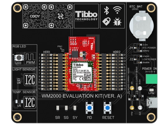
The newly released WM2000EV is an elegant kit for evaluating the capabilities of the WM2000, Tibbo's programmable Wi-Fi/BLE module.
The kit was designed to be completely self-contained and enable the exploration of the module's features without having to wire in any external circuitry. To this end, the board comes equipped with all essential buttons and status LEDs, temperature and light sensors, as well as a PWM-controlled RGB LED. The included CR2032 battery (installed in a holder) can be used to test out the WM2000's low-power "sleep" mode, in which the RTC continues operating and can wake the module up at a preset time.
To aid you in learning about the WM2000's features and capabilities, we have prepared a tutorial featuring a variety of projects.
Your journey begins with testing the IoT/sensor application that comes preloaded on the kit's WM2000. Follow the accompanying step-by-step guide, and in as little as 10 minutes you will have the WM2000 connected to and reporting the measured temperatures and light levels to the Keen service.
The second chapter teaches you how to wirelessly upload a different application into the WM2000. This application showcases controlling the board's RGB LED from a modern, non-reloading web page. In this step, you will also learn about the module's ability to store two applications at once.
Further steps will explain wireless debugging, using CODY (our project code generator), debugging code wirelessly, connecting to Microsoft's Azure cloud service, as well as using the WM2000 in BLE-enabled access control applications.
The kit is powered via an included USB-C cable, which can also be used as a wired debugging interface accessible from our TIDE and WebTIDE software. To facilitate debugging, the board's USB port is connected to the serial debugging pins of the WM2000 via a USB-to-serial converter IC. Wired debugging is useful when wireless debugging via Wi-Fi is unavailable or inconvenient.
Two pin headers are provided for easy access to the WM2000's pins. The module itself is held in place by spring-loaded pins and can be easily popped out and back in. The board even features jumpers and test points for measuring the current consumption of the board and the module.
Order Samples Now!
Ubuntu-based Distribution for the LTPP3(G2) Board

To facilitate the rapid development and deployment of Tibbo Project System (TPS)-based automation and IoT applications while offering our users a familiar environment, we have created an Ubuntu-based Linux distribution.
Ubuntu is one of the world's most popular flavors of Linux. It runs on all kinds of platforms and architectures, and there is a massive amount of community resources available for all project types.
Tibbo's Ubuntu-derived distribution is ideal for system integration, one-off projects, low-volume applications, educational props, and rapid prototyping of products, as well as experimentation and exploration. It provides a user experience similar to that of single-board computers such as Raspberry Pi, but on an extendable hardware foundation that was purpose-built for IoT and automation projects.
Those familiar with Ubuntu will find themselves at home on this new distribution offered by Tibbo. For example, there is a Personal Package Archive (PPA) that is accessible directly through the standard package management utility, apt-get. The PPA contains several tools to help you get started with our Ubuntu-based distribution on the LTPP3(G2) as quickly and effortlessly as possible.
The LTPP3(G2) is a member of the TPS family. A popular choice for automation and IoT projects, our TPS lineup includes the mainboards, I/O modules called Tibbits, and attractive enclosures. The LTPP3(G2) is a Linux mainboard designed around our advanced Plus1 chip.
Included in the PPA, the Out-of-Box Experience (OOBE) script simplifies the device's configuration with a series of interactive prompts that guide you through the process of setting up Wi-Fi/Bluetooth connectivity and the board's Ethernet ports for pass-through or dual-port operation.
Despite its young age, our Ubuntu-based distribution is already hard at work at our manufacturing facility in Taipei. For example, we use LTPP3(G2) boards for testing Tibbits during their production. Employing two high-definition cameras and a touchscreen, this system serves as the testbed for different Tibbits. Thanks to the power of the Plus1's pin multiplexing (PinMux), the individual I/O lines of the board can be remapped on the fly to cater to the needs of whichever Tibbit is being tested at the moment — no kernel rebuild or reboot required. On this new distribution, the board's GPIO lines are reconfigurable in code, much like they are in a typical Tibbo BASIC application.
While this effort remains a work in progress, the development of our Ubuntu-based distribution has reached a point where we feel comfortable sharing a working build with you. We have prepared a repository that contains not only the latest working image, but also automation scripts for customizing your builds through Docker.
We invite you to join us in exploring the exciting opportunities opened up by this new distribution. As always, we welcome your feedback to help us deliver useful solutions tailored to your needs.
Visit the LTPP3(G2) Page!
#Tibbo#IoT#IIoT#industrial automation#Industry 4.0#Tibbits#TIDE#WebTIDE#IDE#Linux#Ubuntu#Evaluation Kit#WM2000#LTPP3(G2)
0 notes
Text
Introducing the WS1102 Wireless Serial Controller, New High-Voltage ADC Tibbit, and More
In this issue:
WS1102 Programmable Wireless RS232/422/485 Controller
Tibbit #43-2 — Four-Channel Streaming ADC With a ±200V Range
Python Wrapper for Plus1's PinMux (Peripheral "Switchboard")
WebPWM — RGB LED Control Demo for the WM2000EV Kit
WS1102 Programmable Wireless RS232/422/485 Controller

Meet the newest member of Tibbo's family of programmable serial controllers — the WS1102. This compact, cost-effective device combines Wi-Fi and Bluetooth Low Energy (BLE) interfaces with a universal RS232/422/485 port. Like all members of the DS110x family, the WS1102 ships preloaded with our Serial-over-IP (SoI) application, which has been adapted for the wireless-first nature of this new programmable device server. When running the SoI app, the WS1102 is compatible with Tibbo's well-known TDST software, which includes the Virtual Serial Port Driver (VSPD). To simplify deployment away from traditional Ethernet networks, the WS1102 also comes preloaded with the new SoI Companion App. It implements a configuration interface that can be accessed over BLE from the L.U.I.S. (Loadable User Interface System) smartphone app*. The SoI Companion App provides access to all SoI settings. This makes the WS1102 our first serial controller that can be fully configured from a smartphone. While it was designed with the SoI app in mind, the WS1102 is still a fully programmable serial controller. Programmability makes it ideal for edge Internet of Things (IoT) applications. For example, the WS1102 can be tasked to query serial Modbus devices (something that a remote cloud server cannot reliably do) and then securely send the collected data to the cloud for aggregation and analysis. The WS1102 is based on Tibbo's cloud-native WM2000 Programmable Wireless IIoT Module and thus inherits the WM2000's capabilities. In addition to integrated Wi-Fi (802.11a/b/g/n over 2.4GHz/5GHz) and BLE 4.2, the WS1102 can store two compiled Tibbo BASIC/C application binaries and supports over-the-air (OTA) updates, wireless debugging, and Transport Layer Security (TLS). Native support for TLS1.2 allows the WS1102 to communicate with Microsoft Azure, Amazon Web Services (AWS), Google Cloud, and virtually any other cloud services provider. * The L.U.I.S. app is available for iOS, Android, and as a web app.
Order WS1102 Now
Tibbit #43-2 — Four-Channel Streaming ADC With a ±200V Range
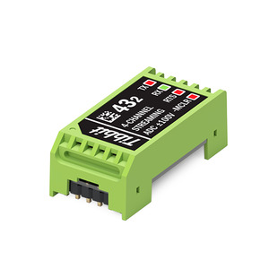
The new Tibbit #43-2 is a wide-input-voltage range version of the #43-1 ADC Tibbit that we introduced back in March. Nominally rated at ±100V in the single-ended mode and ±200V in the differential mode — but with absolute maximum ratings of ±120V and ±210V, respectively — Tibbit #43-2 can even be used to acquire AC signals, for example, in phase detection and power quality factor monitoring systems. Other possible applications include battery bank management, solar panel voltage monitoring and logging, as well as industrial instrumentation. In essence, Tibbit #43-2 adds the capabilities of a multichannel wide-input-range voltmeter to your TPS devices. Like its sibling, the new #43-2 device offers four single-ended or two differential channels and incorporates a microcontroller. The latter enhances the linearity and precision of analog-to-digital conversions and also enables low-jitter signal sampling and data streaming through the serial port.
Order Tibbit #43-2 Now
Python Wrapper for Plus1's PinMux
As a part of the ongoing development of Tibbo's Ubuntu-derived distribution, we've updated our Personal Package Archive (PPA) with a Python wrapper for PinMux. PinMux is a truly unique feature of the Plus1 SoC. It is a "switchboard" that dynamically connects the CPU's peripherals to its GPIO lines. Moreover, such reconfiguration is fully transparent to the OS and does not require a reboot. Flexible remapping of peripherals, while common on lightweight microcontrollers, has hitherto never been implemented on Linux-grade chips in a comprehensive, fully symmetrical manner. The new Python wrapper gives you access to this "switchboard" and allows your code to map and remap peripherals on the fly and as needed. For example, you may dynamically switch a CPU pin from being a GPIO line into acting as the TX line of a UART, stay in this mode for a while, and then turn the pin back into a GPIO line. With traditional Linux CPUs, such reassignments would require editing the device tree and rebooting the system on each change. Not so with Plus1, its PinMux "switchboard," and the new Python wrapper! For more information on the wrapper, see our Getting Started guide.
Get Started Now
WebPWM — RGB LED Control Demo for the WM2000EV Kit

We've just published the next chapter in our guided journey of exploration for the WM2000EV. As you may recall, in the first chapter, we illustrated how the WM2000's native support for Transport Layer Security (TLS) and our streamlined API simplify sending data into the cloud. In the second chapter, you'll first learn how to use the Companion App* to configure the module for connecting to your Wi-Fi network, as well as for wireless debugging. Next, you will use TIDE, our development software for Windows, to upload the WebPWM application into the module. This project is a blueprint for creating cloud-connected lighting control applications with the WM2000 module. Just like with Tibbo's traditional "wired-first" devices, the upload process is as simple as opening a project in TIDE, selecting the WM2000 in the Device Explorer, and clicking Run. Finally, you will access the WM2000 through the application's web interface. The interface demonstrates the dynamic control of the WM2000EV's RGB LED using the module's PWM channels. The modern implementation of the web interface allows controlling the LED in real time — no page reloads required. * The Companion App comes preloaded on every WM2000 and can be accessed via the L.U.I.S. app (available for iOS, Android, and as a web app).
Take the Next Step
#Tibbo#IoT#IIoT#Industrial Automation#Industry 4.0#Tibbits#Linux#Ubuntu#Device Server#Wireless#Serial#WS1102#WM2000EV#Evaluation Kit
0 notes