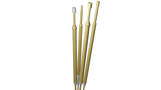
#Spring-loaded contact test probes
Explore tagged Tumblr posts
Visit Tumblr Blog
Explore Tumblr blogs with no restrictions, modern design and the best experience.
Last Seen Tumblr Blogs


Fun Fact
The most popular pages on Tumblr are about Minecraft, GIFs, and David J. Peterson.
Text
Common Challenges in ICT Test Programming and How to Overcome Them
ICT Test Programming is the key component of effective electronic testing, but it comes with its own set of challenges.
Here in this blog, we will look into the challenges of ICT Test Programming and explore the actionable solutions to overcome them.

ICT Test Programming
Comprehensive test coverage is such a significant challenge. It became a challenge when PCBs grew more complex, making it difficult to test each component and connection.
To close these gaps and make sure important regions aren’t missed, automated tools and design-for-testability (DFT) concepts are used to examine test coverage.
Another big hurdle is the fixture design. It’s important to design an exact bed-of-nails fixture that reliably makes contact with every test point.
The solution to this problem is routine maintenance and careful engineering at the future design phase.
Troubleshooting issues: Testing for PCBs can be challenging and time-consuming. Thus, it is essential to use advanced diagnostic tools that can quickly differentiate between actual defects and issues with the test setup. If you systematically approach the debugging, you can efficiently isolate and resolve the issue.
Besides troubleshooting issues, limited test access is also concerning; as the device shrinks in size, the physical access to the test points becomes more and more restricted.
The solution is to employ boundary-scan testing (JTAG) and other non-invasive techniques to test the inaccessible areas.
Furthermore, for many firms, the high expense of ICT programs and fixtures might be a major deterrent. Purchasing high-quality fixtures and software may appear expensive upfront, but it will save money over time by increasing test accuracy and decreasing downtime.
Over time, regular software and equipment upgrades and updates for testing can also help in reducing these expenses.
Ready to overcome your ICT Test programming challenges? Visit Equip-test to explore our range of testing solutions and get started today!
#Spring Contact Test Probes#Spring Loaded Contact Probes#Cable Harness Test#Harness Test Modules#Testing Cable Harness
0 notes
Text
How Pogo Pin Connectors Are Revolutionizing the Electronics Industry
How Pogo Pin Connectors Are Revolutionizing the Electronics Industry
Everything You Need to Know About Pogo Pin Connectors
Pogo pin connectors are the go-to options in modern electronics as they help create safe and stable connections over multiple devices. They can be constantly connected and disconnected, making them preferred choices for doing battery charging, signal transmission, and working in testing environments. Get more news about Pogo Pin Connectors,you can vist our website!
Learn About Enhanced Performance Through Unique Design
Spring-loaded pogo pin connectors are designed to help increase and ensure reliable electrical contact while there is mechanical stress and vibration. With compact and flexible configurations, their use is ideal for high density circuit designs and portable devices.
Wide-Ranging Applications of Pogo Pins
From consumer electronics to automotive, the medical devices aren’t far behind as pogo pins provide high-efficiency connectivity. Commonly they’re used in charging docks, test probes, and high frequency data transfer modules ensuring smooth operation everywhere they're used.
Durability and Reliability In Harsh Environments
Pogo pins stand the test against wear and exposure to extreme temperatures while remaining both functional and effective. They are best used for industrial automation and the tough conditions are deemed perfect for mission critical applications.
XINTENG Pogo Switch Solutions
XINTENG has pogo pin connectors for various applications across industries. Our engineering capabilities enable us to create design solutions for consumer electronics, automotive, and industrial systems. We concentrate on working with precision and efficient connectivity solutions.
0 notes
Text
Benefits & Advantages of Pogo Pins
Pogo pins are spring-loaded probes are pressed into a hole to connect two PCB boards together. It allows an electrical connection to any component with a copper pad. There are different types of Pogo pins to allow for different connection policies, as well as different signal types and voltages. They are mostly used for testing electrical signals on printed circuit boards.
Advantages of Pogo Pins:
Easy to maintain: If an electronic component failure occurs while implemented with connectors can quickly replace the failed component parts.
High Life Span: The pogo pins have a great life span as compared to other connectors.
Improves the production process: Pogo pin Connector not only simplify parts of electronic products but also simplifies the production process.
Strong Durability: When reduced, the pogo pin connector contact point position unchanged can maintain a stable connection point. Pogo pin connectors are common in our daily lives and are widely used.
Like pogo pins, waterproof connectors have a thin body that is easy to carry for the user. It is used in a wet, areas where water pipes are used or raining climate for connecting purposes due to its double-layered metal body. And A PCB Connector connects electrical components on a conductive track or between pads on the board. Some devices hold more than one PCB and will utilize a type of equipment to build a connection between the boards. PCB is typically used to transfer signals or power from one PCB to another or to transfer to or from the PCB from another source within the unit.
Adam-tech is the custom connectors and waterproof connector service providers. Their ability is to provide all types of connecting cable assembly at a convincing and fair price. We promise you to provide you with the best connectors of great quality. For us, customer satisfaction is the first promise.
0 notes
Text
Produce Food Safety Rule
The Food Safety Modernization Act passed into federal law more than 7 years ago. It was a top-to-bottom rework of our food safety system. The overarching notion: shift the way that food safety works in the US from reaction to prevention. To that end, the federal government has spent the better part of a decade rulemaking, planning, and preparing – like the Produce Food Safety Rule.
Now, we’re finally in the first part of the FMSA rollout. That means a lot of work for pretty much everyone engaged in the business of growing or making food. One of the provisions in the FMSA is a produce safety rule that calls for, amongst other things, routine inspections of those who produce the produce.
A Long Time Coming
As reported by Food Navigator and Food Dive, the process of rolling out those inspections has gone a bit slower than expected. Now, in the spring of 2019, the FDA will start them for the largest farms growing fruit and veggies for domestic or international sale
The structure of the rollout resembles that for other aspects of the FMSA. First, the largest businesses will be subject to the rule. Small farms won’t be subject to inspections probing their compliance with the new rule until 2020. And it’ll be years yet before the FDA starts inspections for farm water.
But it will address imported foods:
“At that time, U.S. produce farmers, and those in countries that export to the United States, had never been subject to this level of federal food safety oversight and, quite frankly, we at FDA had a lot to learn about the unique challenges farmers face every day,” Gottlieb said in the Feb. 7 statement. “The idea of implementing preventive measures to head off food safety problems was a new and modern approach to regulation that promised to bring significant benefits for consumers.”
FSMA – Addressing Current Food Issues?
Given that the FMSA was passed into law back in 2011, it makes sense that it wasn’t written as a reaction to recent events of food poisoning. As some of you probably already know, recent outbreaks have been traced back to farm water tainted with microbes that can cause foodborne illness. The best known of those cases was probably the contamination of lettuce in Yuma, Arizona last winter.
That incident might be seen as cause for urgency. The government hasn’t systematically tested water for contaminants on farms before, however. Accordingly, it’s going to take a while to figure out how such testing is going to be done and to get the infrastructure into place to actually do it.
Farmers can get ready for the new requirements by signing up for an on-farm readiness review, or OFRR. It’s pretty much what you would expect: farmers sign up for someone from their state’s agriculture department or extension to come by their farm and give them the lowdown on what they need to do to get ready for the coming inspections. According to Food Navigator and Food Dive, some 350 farmers have already signed up for this program.
Farmer Training
According to Food Navigator, funds for farmer training through the State Produce Implementation Cooperative Agreement. $85 million went to different state-level health departments to help contact, educate, and onboard farmers to the program. The website reports that one of objectives of the program is to build out a system in which the bulk of inspections are farmed out to state inspectors who are familiar with the terrain; some inspections will be carried out by the FDA, but they’ll mostly be focused on states which haven’t opted into the cooperative agreement.
Hopefully, all those resources have put the farmers in a good place for what’s coming. The FDA will start inspections this spring, as we said above, and they’ll be looking into compliance with regulations that deal with all sorts of different aspects of growing produce. Farmers will need to make sure that their buildings and equipment are up to date. They’ll have to watch out for what their animals are doing, where they’re wandering, and what’s being done with their waste. There are specific rules for how workers should be trained and what hygiene practices they need to follow.
If you’re growing sprouts, which are particularly susceptible to foodborne illness and thus considered to be a high-risk food, there’s a whole separate set of rules that you need to get in line with. If you’re a sprout grower and this is news to you, you can find the guidelines on the FDA website.
The rules at play here are complex, and even with the assistance of state and local health departments, it’s likely to be a difficult rollout process. That’s why the FDA is starting with the largest farms first; they have the capital and the capacity to effect the changes necessary and to give the federal agency an idea of how the rollout process is going to go. Hopefully, it goes smoothly, and they’ll learn what they need to before the changes come into place for smaller farmers in the near future.
By our lights, on-site produce inspections are long overdue. This is an important step in shifting our food safety system from one that’s reactive to one that’s preventative. Hopefully, it’ll drive down the number of food-safety related incidents and lead to more trust in the food that people eat.
The real holy grail, however, is active testing of water for bacterial load and for other contaminants. That’s something that’s desperately needed and still a few years away. Some farms have already committed to doing these inspections themselves; the association of lettuce growers in California has their own requirements, for example, that call for this amongst a host of other things.
That’s good, but we need everyone to do it. Here at Make Food Safe, the debuting of new regulations and testing regimes are a bit like Christmas; they’re steps towards a world in which we have a better idea of what’s going on with our food. We can’t wait until it’s not just the produce but the water that’s getting inspected.
By: Sean McNulty, Contributing Writer (Non-Lawyer)
The post Produce Food Safety Rule appeared first on The Lange Law Firm.
0 notes
Text
Simple Flex Circuit Quality Control
DRC Check
The Design Rules Check (DRC) is one of the most important steps in flex circuit quality control. Upon receiving an order, use this automated tool to verify if the layout does not have any addressable layout errors, such as specific placement or routing. The DRC check verifies the layout and netlist against the flexible PCB design rules and constraints.
The DRC examines the component placement of the board and traces the routing integrity for components that overlap, pins that are untraced, and incorrect layer placement among other constraints.
Our system also does the manufacturing rule check in order to ensure that the flex circuit design can be manufactured.
Automated Optical Inspection (AOI)
Automated optical inspection is more repeatable and reliable than the manual visual inspection. Use automated optical inspection to test the inner layers of flexible PCBs that are multi-layered. In this method, the surface of the flexible PCB is visually scanned by several light sources that light the board. A number of high definition (HD) cameras or a scanner observes the surface. As a result, all areas of the flex circuit’s board can be monitored.
The automated optical inspection for a bare flexible PCB board detects the following features:
Spacing violations
Hole breakage
Cut traces or pads
Missing pads
Line width violations
Excess copper
Shorts circuits
Restriction of Hazardous Substances Directive (RoHS)
The RoHS has restrictions for the use of six hazardous materials in the production and manufacturing of various electrical and electronic equipment. The flexible PCBs should be free from hexavalent chromium, flame-retardants polybromide biphenyl, polybromide diphenyl ether, lead, cadmium, or mercury. All your products should comply with the RoHS requirements.
Electrical Testing
Prototype Orders
For small volume and prototype orders of flex circuits, you can use Flying-Probe E-Test. Your clients’ flexible PCB board should be analyzed through a Flying-Probe E-Tester. This tester checks for open circuits, short circuits, and ensure that the nets that we make are the same as the ones for your design. The process is efficient, and it ensures that the fail rate of your PCB boards will be not more than 1%.
Production Orders
Production orders are tested using testing fixtures. For instance, the traditional electronic test fixtures such as a bed of nails tester have many pins that are placed in holes in an epoxy phenolic glass cloth laminated sheet, which is aligned by tooling pins in order to make contact test points that are on the PCB.
The traditional electronic test fixtures comprise an array of spring-loaded pogo pins that make contact with a node in the circuitry of the device on test (DUT). Reliable contact is quickly made with thousands of individual test points that are within the DUT circuitry.
This tester also checks for open circuits, short circuits, and ensure that the nets that we make are the same as the ones for your design. The process is efficient, and it ensures that the fail rate of your PCB boards will be not more than 0.1%.
UL Certification
All your products should comply with the UL safety certification 94V-0. Your flexible PCBs should satisfy all the UL requirements and meet the flame rating 94V-0. The typical rating of flexible PCB material should be at least 94V-1. Note that the higher the number, the lower the rating, for instance, 94V-0 has a higher rating than 94V-1. Our manufacturing process and materials are subjected to UL inspections.
The post Simple Flex Circuit Quality Control appeared first on PCB Labs.
source https://www.pcblabs.com/simple-flex-circuit-quality-control/ source https://pcblabscom.tumblr.com/post/182911857140
0 notes
Text
Simple Flex Circuit Quality Control
DRC Check
The Design Rules Check (DRC) is one of the most important steps in flex circuit quality control. Upon receiving an order, use this automated tool to verify if the layout does not have any addressable layout errors, such as specific placement or routing. The DRC check verifies the layout and netlist against the flexible PCB design rules and constraints.
The DRC examines the component placement of the board and traces the routing integrity for components that overlap, pins that are untraced, and incorrect layer placement among other constraints.
Our system also does the manufacturing rule check in order to ensure that the flex circuit design can be manufactured.
Automated Optical Inspection (AOI)
Automated optical inspection is more repeatable and reliable than the manual visual inspection. Use automated optical inspection to test the inner layers of flexible PCBs that are multi-layered. In this method, the surface of the flexible PCB is visually scanned by several light sources that light the board. A number of high definition (HD) cameras or a scanner observes the surface. As a result, all areas of the flex circuit’s board can be monitored.
The automated optical inspection for a bare flexible PCB board detects the following features:
Spacing violations
Hole breakage
Cut traces or pads
Missing pads
Line width violations
Excess copper
Shorts circuits
Restriction of Hazardous Substances Directive (RoHS)
The RoHS has restrictions for the use of six hazardous materials in the production and manufacturing of various electrical and electronic equipment. The flexible PCBs should be free from hexavalent chromium, flame-retardants polybromide biphenyl, polybromide diphenyl ether, lead, cadmium, or mercury. All your products should comply with the RoHS requirements.
Electrical Testing
Prototype Orders
For small volume and prototype orders of flex circuits, you can use Flying-Probe E-Test. Your clients’ flexible PCB board should be analyzed through a Flying-Probe E-Tester. This tester checks for open circuits, short circuits, and ensure that the nets that we make are the same as the ones for your design. The process is efficient, and it ensures that the fail rate of your PCB boards will be not more than 1%.
Production Orders
Production orders are tested using testing fixtures. For instance, the traditional electronic test fixtures such as a bed of nails tester have many pins that are placed in holes in an epoxy phenolic glass cloth laminated sheet, which is aligned by tooling pins in order to make contact test points that are on the PCB.
The traditional electronic test fixtures comprise an array of spring-loaded pogo pins that make contact with a node in the circuitry of the device on test (DUT). Reliable contact is quickly made with thousands of individual test points that are within the DUT circuitry.
This tester also checks for open circuits, short circuits, and ensure that the nets that we make are the same as the ones for your design. The process is efficient, and it ensures that the fail rate of your PCB boards will be not more than 0.1%.
UL Certification
All your products should comply with the UL safety certification 94V-0. Your flexible PCBs should satisfy all the UL requirements and meet the flame rating 94V-0. The typical rating of flexible PCB material should be at least 94V-1. Note that the higher the number, the lower the rating, for instance, 94V-0 has a higher rating than 94V-1. Our manufacturing process and materials are subjected to UL inspections.
The post Simple Flex Circuit Quality Control appeared first on PCB Labs.
source https://www.pcblabs.com/simple-flex-circuit-quality-control/
0 notes
Text
Новости сайта #ENGINEERING - 工程
New Post has been published on http://engineer.city/reinventing-the-probe-pin/
Reinventing the probe pin
By redesigning and fully automating the manufacturing process, spring probe pins can now deliver high performance at price of a stamped contact for high density, fine pitch applications
For decades the spring-loaded probe, aka pogo-style pin, has delivered excellent mechanical and electrical performance in a highly compliant contact. However, this often came at a high cost given that each pin is constructed of three to four discreet parts manufactured and assembled in a laborious, less-than-fully-automated process.
The cost could be so exorbitant, in fact, that when large volumes of pins are required, many opted to use less compliant, lower performance alternative contact technologies to reduce costs. This approach is becoming less viable, however, with the increasing miniaturisation of integrated circuits, electronic components and devices that pack more circuitry into smaller footprints.
A single test socket for reliability and burn-in testing, for example, can require hundreds and even thousands of spring-loaded probe pins in a fine pitch configuration. The same applies to board-to-board compression connectors. When factoring in multiples of test sockets as well as production-level quantities of connectors, pin quantities can literally run into the millions.
Enter, or perhaps re-enter, the spring probe. With a new approach to pin design and a complete re-invention of the manufacturing process, miniaturised spring probes as small as .2mm are now available that provide a high temperature, current and bandwidth performance pin at the price of a stamped contact.
Traditional pogo-style pins
Although designed and manufactured in subtly different ways, the pogo-style pin is typically constructed of a pin, two plungers and a spring encapsulated in a metal shell.
This style of pin is highly compliant, which means it is designed to compress or ‘comply’ during insertion. This is critical when attempting to maintain a good connection despite potentially uneven surfaces, varying heights, errors in parallelism and flatness, or pivoting or rotating elements.
Although compliancy can be achieved by other techniques, such as bends, buckles, or cantilever-style contacts, additional space between pins is required during compression. Spring-loaded pins operate in a purely vertical fashion, so the maximum space occupied at any time is defined by its diameter. This allows for placement of spring-loaded pins in fine pitch distances as low as .2mm.
The trend toward more compact, high density electronics design – defined as the number of pins in a small area or the distance between pin centres – is already impacting several markets.
One market that regularly utilises fine pitch spring probes is for electronics reliability testing, including burn-in, HTOL, HAST, THB and other testing protocols. To conduct this type of testing, sockets are manufactured to provide an intermediate (temporary) connection through an array of pins between the printed circuit board (PCB) and the components or multi-chip modules being tested. The PCB is then connected to a computer or other device for data capture and analysis to determine pass or fail.
The other market is compression-style board-to-board connectors used in electronics for telecom, automation, medical, aerospace, and military applications. These speciality connectors use spring probe technology to create a one-sided connector that is mounted against pads on the PCB. The benefits of spring-loaded connections include the elimination of receptacles to reduce costs, space savings, ‘one-touch’ attachment and removal, and high durability.
Whether creating a temporary connection, such as for testing, or as a permanent board-to-board interconnection, the common denominator is more pins, less real estate.
“Devices used to have 2,000 pins in a two inch square area. Now they want the same 2,000 pins in a one-half inch square and the only way to do that is to reduce the pitch of the device,” says Ila Pal, COO of Ironwood Electronics, a manufacturer of high speed sockets and adaptors for characterisation, burn-in, and production testing.
“We were using spring probe pins on a 1mm pitch design and more recently at .5mm,” explains Pal. “Then, last year, there were requests to shrink the pitch to .4mm. Now, we are moving even further down to .35mm”
Germany-based test socket manufacturer EP Ants, is experiencing the same market trend. According to Rick Taylor, president and co-founder, 70-80% of the test sockets his company manufactures today are for high-density applications.
According to Taylor, another market driver is price. Higher density means a higher volume of pins per test socket. Multiply that by the number of sockets required for parallel or serial testing at a single facility and customers expect companies such as EP Ants to deliver the best possible price without sacrificing performance.
“As everything gets smaller and the density gets tighter, pin counts are increasing,” says Taylor. “At the same time, our customers expect to reduce their costs. So we challenge ourselves to find ways to manufacture our sockets at an achievable price whenever possible.”
So when Taylor heard about a spring-probe called the H-Pin that could deliver high performance at a considerably lower price, he was immediately intrigued.
The H-Pin is a stamped spring probe that delivers the mechanical, electrical and thermal performance of a pogo-style spring probe. The highly compliant pin has a working range up to 1mm with a flat spring rate and can be used up to 15GHz with -1.0dB loss, carry up to 4 amps of current and withstand temperatures up to 200°C.
Although there are a few design tweaks, the real departure is in the manner in which complete pin assemblies are manufactured using a high volume BeCu stamping process and a 100% automated, high speed assembly and inspection process that can produce up to 400 pins per minute.
Available in various lengths and pitch sizes as low as .2mm, the product is the brainchild of Plastronics, a provider of test sockets for semiconductor reliability testing.
Depending on quantities, the spring-loaded probe pins can cost 30-50% less. With thousands of pins potentially in a single test socket or board-to-board connector, the savings can be considerable.
According to Taylor, simply reducing the cost meant little without consistent pin quality. To ensure this was the case, EP Ants conducted extensive testing of the H-pin, which included inviting customers to also test the product and provide additional feedback.
“As a test socket manufacturer, we have to rely on the quality of the pins we get from our spring probe supplier,” says Taylor. “The H-pins have a very reliable quality level, which is extremely important to us and our customers.”
Meeting high performance demands
For spring-loaded probes pins, high performance characteristics are defined by the ability to withstand high temperatures required for burn-in and other tests, ability to handle increasing amounts of current over increasingly smaller pins, and the ability to handle high frequencies.
According to Taylor, they do not rely on a single pin manufacturer. However, his company uses the H-pins for high temperature burn-in, tri-temp and HAST testing where the spring-probe is regularly subjected to temperatures well in excess of 200°C.
“The H-Pin works well when exposed to the high temperatures we use for burn-in or tri-temp testing,” says Taylor. The tests are typically conducted at up to 240°C and, despite cooling the back side, the spring pins still experiences a fair amount of temperature. “We have worked with these pins above 200°C and we did not have a problem where other pins have failed.”
Pics: Putting through three but no need to use all if there’s not space – just pick whichever looks best.
Tags:
fasteners
design
probe pin
H-Pin
Plastronics
Images:
Categories:
Design Engineer
Fasteners/Sealing
Source: engineerlive.com
0 notes
Text
Enginology: How and Why Certain Engine Modifications Work…or Don’t
From time to time, some discussion and review of certain common modifications can be worthwhile
Sometimes gaining knowledge about “why” or “how” certain engine modifications work can lead to a clearer understanding about related changes that can also be helpful. For example, I benefitted a significant amount by having a chance to do periodic projects with an engine “thinker” who would almost always ask me what I thought certain modifications would do before specific tests were run. This forced me out of the comfort zone of “let’s just see what happens” into a box that made me think about “what can we expect to see and why” before we pulled the trigger. Over time, it changed the way I thought (and still think) about how engines work (or don’t). His name was Yunick.
Suppose we kick this off with a brief discussion about carburetor spacers. For example, let’s narrow the subject to one that contemplates the distance from carburetor base to plenum chamber floor. It is in this space that air/fuel mixtures are subjected to not only dynamic pressure changes but directional ones as well. And it is this process of “turning” from carburetor base into the manifold’s runners that fuel and air can become mechanically separated. Keep in mind that in this zone beneath a carburetor, we have two combined (hopefully) substances of considerably different masses. Furthermore, air (compressible) can more easily change direction than fuel (far less compressible). Given the environment just described, raising (or lowering) a carburetor from where the manifold’s carburetor mounting flange is initially located tends to change this dynamic.
Also, we need to keep in mind that a carburetor is a “pressure differential device” that operates with atmospheric pressure pushing on the carburetor and into a region of pressure that’s less than atmospheric. The engine isn’t “sucking” air into its combustion spaces, atmospheric pressure is forcing it into these spaces, largely due to the pressure differential that exists between them. This is principle for why special attention should be given to a carburetor’s bowl vents, making certain they can clearly see undisturbed atmospheric pressure, or at least as close as possible to atmospheric. More on this in a bit.
If we want to call this pressure below the carburetor (as seen by atmospheric pressure) a fuel metering “signal,” then raising or lower a carburetor (relative to the plenum chamber’s floor) will alter this signal, thus affecting the amount of fuel delivered by the carburetor, all else being equal. So while total air flow may remain comparatively the same, changing the height of the carburetor can alter fuel flow. More specifically, raising a carburetor weakens signal, lowering it strengthens the signal.
We mentioned fuel bowl vents. It’s important, particularly on the track and with some sort of air filtering device in place, that bowl vents only experience atmospheric pressure, or at least as close to this as possible. Failure to accomplish this can interrupt proper fuel flow (as based on whatever calibration/jetting is being used). It’s possible to mount small pressure-measure probes proximate to the bowl vents to determine what sort of pressure environment (including fluctuations) the carburetor is experiencing, especially on the track.
Worst case, you can perform such measurements during an engine dyno test that includes whatever air cleaner is being used. And while this doesn’t contemplate on-track pressure conditions, it’ll enable you to determine if any reversion pressure pulsations (as a function of load and rpm), may exist. We also suggest you take this concern lightly. We’ve seen reversion make the underside of a carburetor look like the inside of an exhaust pipe. You cannot image how difficult it is to calibrate a carburetor under these conditions, especially if the engine sees rpm less than at peak torque on the track.
Before we leave the bowl vent topic, just one additional thought. If you’re uncertain about or having difficulty determining pressure conditions around (or inside) the bowl vents, there’s always the long-used solution of connecting them with a section of rubber hose and cutting a “notch” in the middle (on top), thus exposing both vents to atmospheric pressure.
And, by the way, if the installation of a 4-hole spacer helps power, it’s likely that the engine was experiencing a “lean” mixture condition or having an air/fuel separation problem before the spacer was installed. Why? Well, in reality, a 4-hole spacer will increase the fuel metering signal but doesn’t really make the engine think you’ve raised the carburetor, given no other possible problems that it may have cured. But like we said, it this works, you should probably be looking elsewhere to identify the problem.
It’s important that while you’re doing all this experimenting with carburetor height that you keep a keen eye on the brake specific fuel consumption numbers. For example, if you find that an unreasonable amount of fuel is being required to best power, watch for b.s.f.c. date to be high as well. A quick guide to “what’s a good b.s.f.c. number” is often provided by checking the brake number at peak torque. If an unusual amount of fuel is required for best power at higher engine speeds, you’ll see this reflected in comparably higher b.s.f.c. data. Bottom-line? Raising or lower carburetor height (relative to the manifold’s plenum floor) can alter engine conditions beyond just the plenum floor.
Next up is header collectors and what they largely tend to affect. First of all, a header collector can be compared to an intake manifold plenum chamber. However, because it isn’t practical to build plenum volumes to the extent they will provide a measureable impact on torque output, header collectors become the focal point. For all practical purposes, header collectors have little influence on torque above an engine’s indicated peak torque rpm. However, below this point they do. Basically, increasing header volume provides an additional torque boost below this point, decreasing the volume tends to reduce torque. In fact, you can cause a material reduction in torque below the peak rpm point (as some sprint car engine builders know) by removing the collectors all together and simply merge the primaries into one cone. So, in a sense, it an engine is to be primarily operated at an rpm below its peak torque engine speed, no collectors are needed at all.
You may be interested to know, if you don’t already, that a header collector cross-over pipe that joins the collectors will essentially add collector volume and further enhance torque below peak torque rpm. So if you’re looking for some additional boost off corners or, on occasion, engaged in passing where lower engine speed becomes involved somewhere in the move, this is a option for you to consider.
Now let’s take a quick look at what is commonly called “valve float.” Maybe this term is a bit mis-leading, in that the valves do experience two conditions that have been said to cause “float.” But regardless of what we may call them, the problem is based on a lack of valve control.
Overall, there are two times in the movement of a valve when it can be uncontrollably off its seat. One can come during high rpm operation when the valve lifter is briefly separated from the camshaft’s lobe. This is often called “pitch.” And then during times when a valve is re-seated and it fails to momentarily remain seated. This is usually termed “bounce.” The important point here is that if there is not physical contact between a valve head and piston crown, valve spring damage has occurred (a loss of operating pressure) and requires spring replacement. It’s the audible part of these possible events that we associate with a “float” condition.
Spring research/development on a “spin” machine has shown that valve spring damage can (and does) occur even prior to any audible signals from the valve train. In fact, if you’ve already heard this condition develop (often difficult because of overriding open exhaust header noise), the chances are pretty good it’s spring replacement time. Worst case, at least run a pressure check on all the springs to determine the extent of the damage.
If you have a favorite “myth” about how certain engine modifications actually cause a change in performance, let us know and we’ll include them the next time we visit this part of the engine building world. There seems to be there’s always be a reason why such modifications actually do (or don’t) what they are intended to do.
The post Enginology: How and Why Certain Engine Modifications Work…or Don’t appeared first on Hot Rod Network.
from Hot Rod Network http://www.hotrod.com/articles/certain-engine-modifications-work-dont/ via IFTTT
0 notes
Text
Advanced Test Adapters for All System
Equip your system with Eqip-Test’s Test Adapter, designed for seamless integration and precise system testing. With this, you can also streamline your testing process by delivering accurate results every time. Visit our site and find the perfect adapter for your testing requirements! Call us at +361 533 3165 to talk to our experts if you want to know this in more detail.
0 notes
Text
Buy Now Flying Probes From Equip Test
The concept of a flying probe test that accesses components on printed circuit assemblies (PCAs). Flying probe upgrades bed of nail fixture and takes advantage of probes to replace bed of nails. The flying probe technology tests the boards without using a special bed of nails adapter. For more information visit https://bit.ly/3yq0wgP
#test probes#spring contact probes#ingun test probes#RF testing#radio frequency testing#Flash Fixture#Flying Probes#IPTE#mass interconnect#sockets#FCT#VPC#Interface#Test Socket#spring loaded contact probes#receptacles#Flash programming#Functional Test#kelvin probe#ICT
0 notes
Text
Cable Harness Test
Equip-Test has manufactured high-reliability Cable Harness Test Systems for large equipment. Such equipment is highly-used in vehicles and for missile level cable-harness tests. They are implemented using a high voltage insulation measure module, high-voltage matrix switch, and precision millimeter. If you want to know more about our products, please call us at +36 1 533 3165. For more information visit https://bit.ly/3P8cCC3
0 notes
Text
Order High-Quality Spring Loaded Contact Probes Online
If you’re looking for the finest quality Spring Loaded Contact Probes, you’re on the right page. We offer the industry‘s best spring-loaded contact probes known for their durability and precision. Take a look at our website {{URL}} to explore our collection and make the right investment in your testing equipment. Order today and enjoy fast shipping. Any questions in mind? Talk to our experts at +361 533 3165.
0 notes
Text
Top 5 Mistakes OEMs Make When Ordering ICT Fixtures
Imagine this: you're holding a sleek new smartphone, a cutting-edge medical device, or a car key fob that effortlessly connects to a smart vehicle. Behind the scenes, these modern marvels owe their flawless function to a critical yet often overlooked piece of engineering: the ICT Fixture.
In the world of electronics manufacturing, even the tiniest defect can lead to costly recalls, product failures, or customer dissatisfaction. That’s why In-Circuit Testing (ICT) remains a gold standard for ensuring quality and reliability. But for ICT to do its job effectively, it needs a sidekick built for precision and performance—the ICT Fixture.
Whether you're an OEM, a test engineer, or just curious about how complex circuit boards pass the quality test, this article breaks down why ICT Fixtures are the quiet heroes behind electronics you trust every day—and how they can transform your testing process from good to great.
Understanding the Basics: What is an ICT Fixture?
An ICT Fixture, short for In-Circuit Test Fixture, is a specialized mechanical tool used during the In-Circuit Testing (ICT) process. It connects the PCB to the test equipment using a bed-of-nails configuration, where spring-loaded test probes make contact with specific test points on the board.
These fixtures are engineered to precisely align with a given PCB layout. Once the board is placed on the fixture and clamped down, the ICT system runs a comprehensive battery of tests, verifying resistors, capacitors, transistors, diodes, solder joints, and even integrated circuits.
ICT Fixtures are essential in catching production faults such as:
Solder bridges
Missing or misaligned components
Open circuits
Incorrect component values
In high-volume manufacturing, the ICT Fixture becomes a gatekeeper of quality, ensuring that defective boards are identified and corrected before final assembly.
Why ICT Fixtures Still Matter in an Evolving Industry
With the rise of surface mount technology (SMT), miniaturization, and increasingly complex multilayer PCBs, some manufacturers have shifted towards automated optical inspection (AOI) or boundary-scan testing. But ICT Fixtures continue to offer advantages that are difficult to replace:
Comprehensive Component-Level Testing: ICT can test passive and active components under power conditions—something AOI or X-ray inspection can't provide.
Speed and Efficiency: For high-volume assembly lines, ICT Fixtures reduce testing time dramatically. Once the fixture is built, each board can be tested in seconds.
Repeatability and Accuracy: With well-designed fixtures, testing results are reliable and repeatable across thousands of units.
Integration with Functional Testing: Many manufacturers are now integrating ICT with functional test stations for a holistic quality assurance approach.
Custom ICT Fixtures: Precision is Everything
One-size-fits-all doesn't apply in the world of ICT Fixtures. Each fixture must be customized to the unique layout of a PCB. This means close collaboration between fixture manufacturers and the client’s engineering teams.
From choosing the right probe types to designing ergonomic enclosures, every detail matters. High-end fixture designers also provide value-added features such as:
Vacuum hold-down mechanisms
Pneumatic clamping systems
Guided probe modules for high-density test areas
ESD-safe materials
Easy-change fixtures for multi-product testing
If you're looking for a partner that combines cutting-edge fixture design with proven reliability, Equip-Test offers a range of ICT Fixtures tailored for various industries—from automotive and telecommunications to consumer electronics and medical devices.
Choosing the Right ICT Fixture Partner
When selecting a provider for your ICT Fixture needs, consider the following factors:
Experience and Industry Knowledge: A provider familiar with your specific sector will anticipate layout challenges and compliance requirements.
Customization Capability: Each board is different. Your partner should offer 100% custom fixture builds based on your PCB Gerber files and test requirements.
Support for Test Program Development: Some fixture companies also offer ICT test programming, which helps reduce your internal workload and ensures compatibility from the get-go.
Turnaround Time: In fast-moving production environments, lead time matters. Look for suppliers that can deliver quality fixtures quickly without sacrificing precision.
Equip-Test stands out in this space, offering not only custom ICT Fixtures but also full support for test programming, fixture repair, and upgrades, ensuring long-term value for your investment. Learn more here: https://bit.ly/3RfmPhU
Final Thoughts: ICT Fixtures Keep Your Production Flowing
In a world obsessed with innovation and rapid product cycles, it's easy to overlook the critical role of quality control. But make no mistake—without robust ICT Fixtures, the risk of faulty electronics slipping into the market rises sharply.
By investing in high-quality ICT Fixtures and partnering with experts who understand your testing challenges, you’re building a manufacturing process that’s not only fast and efficient but also trusted.
If you're ready to elevate your testing capabilities and improve PCB validation, consider working with a seasoned team like Equip-Test. Precision matters—and so does your reputation.
0 notes
Text
How to Choose the Right Manual Fixture for Your Testing Needs: A Step-by-Step Guide
In the world of electronics testing and precision manufacturing, the right tools can make the difference between flawless performance and costly rework. Among those tools, the manual fixture plays a pivotal yet often underrated role in ensuring quality, consistency, and efficiency. Whether you're testing PCBs, wiring harnesses, or microelectronic components, selecting the ideal manual fixture is crucial for optimizing test results and minimizing downtime.
But with countless configurations, materials, and functions available, how do you determine which fixture is best suited for your testing environment?
In this guide, we’ll break down the key steps and considerations to help you choose the perfect manual fixture for your specific needs—whether you’re a test engineer, production manager, or quality control specialist.
Step 1: Define Your Testing Objectives Clearly
Before exploring fixture options, clarify what you want the fixture to accomplish. Are you focused on functional testing, continuity testing, or high-voltage isolation? Will it be used in a high-volume production environment or for prototype verification?
Understanding your goals will help narrow down the required features, such as:
Contact type (spring-loaded pins, pogo pins, etc.)
Force requirements
Number of test points
Load/unload speed
At Equip-Test, manual fixture solutions are available for everything from standard bed-of-nails setups to fully customized designs tailored to specific PCB layouts and test flows.
Step 2: Assess the Component or Board Geometry
Next, evaluate the physical characteristics of the unit under test (UUT):
What are the dimensions of the board or component?
Are there connectors or edge contacts?
Does the test require double-sided probing?
These factors will influence the fixture’s platform size, the arrangement of test probes, and whether a top-side pressure plate or vacuum hold-down is necessary.
Equip-Test offers both standard and modular manual fixture systems, making it easier to accommodate complex board geometries without reinventing the wheel every time.
Step 3: Choose the Right Probing Technology
One of the most critical aspects of a manual fixture is the selection of test probes. Depending on the signal integrity, current rating, and pitch requirements, you might need:
Standard spring-loaded probes for through-hole or SMT pads
High-frequency probes for RF circuits
Kelvin probes for low-resistance measurements
Special probes for surface wear or sensitive contacts
Don’t overlook the importance of probe life cycle and accessibility, especially in high-throughput environments.
Equip-Test's vast test probe catalog is engineered to support virtually every test scenario imaginable, ensuring precision and durability.
Step 4: Factor in Ergonomics and Operator Safety
Manual fixtures should not only be functional but also comfortable and safe to use. Consider:
Lever mechanisms or pneumatic assist for high-contact-count boards
Clear visibility and easy access to the DUT
Built-in ESD protection
Shielding for high-voltage applications
A poorly designed manual fixture can increase operator fatigue and error rates. Ergonomic enhancements also reduce the risk of repetitive strain injuries during continuous operation.
Step 5: Plan for Scalability and Maintenance
If your test needs might change in the near future, it’s wise to invest in a modular or upgradable fixture. Look for designs that allow:
Easy probe replacement
Interchangeable probe plates
Quick fixture swaps for different board versions
This is where modular fixture platforms from Equip-Test really shine. These fixtures can be easily reconfigured or upgraded, providing flexibility without excessive downtime or new tooling costs.
Step 6: Work with a Trusted Fixture Manufacturer
Even with a clear checklist, designing the perfect fixture isn’t always DIY-friendly. Partnering with a company that specializes in test fixture development ensures:
Optimal layout and mechanical design
High-quality materials and build
Fast turnaround and support for modifications
Integration with test equipment (ICT, functional testers, etc.)
Equip-Test has been at the forefront of manual fixture solutions for years, supporting global electronics manufacturers with robust, reliable test platforms. Whether you're outfitting a new production line or upgrading legacy systems, their engineering team brings unmatched expertise to every custom fixture build.
Final Thoughts: Precision Starts at the Fixture
Your test equipment is only as good as the connection it makes with the unit under test—and that connection starts with a well-chosen manual fixture. By carefully considering your application requirements, board design, probe technology, ergonomics, and future needs, you can ensure accurate, repeatable test results while keeping costs under control.
Ready to explore your options or need expert advice? Visit Equip-Test to discover high-performance manual fixtures designed to elevate your testing process from the ground up.
0 notes
Text
Understanding ICT Test Probes: Essential Tools for Electronic Testing
In the electronics manufacturing sector, In-Circuit Test (ICT) Probes are indispensable instruments. Their ideal test case is to test the integrity and functionality of printed circuit boards (PCBs).
Here in this article, we will look into the significance of ICT Test Probes, their uses, and their advantages in detail.
ICT Test Probes What are ICT Test Probes?
ICT test probes are spring-loaded instruments designed to reliably connect electrically to PCB Test spots. They are employed in automated test equipment (ATE) to conduct in-circuit testing, which involves the overall checking of the electrical performance of individual and overall components.
Applications of ICT Test Probes:
ICT Test Probes are extensively used in many industries, such as:
Telecommunications: Ensure the reliability of communication devices
Automotive Sector: Testing of vehicle electronics along with Electronic Control Units (ECUs)
Medical Devices: Ensure the functionality of medical equipment
Consumer Electronics: Examines how well appliances and devices are working.
Benefits of ICT Test Probes:
Benefits of using ICT Test Probes include:
Accuracy: These instruments deliver accurate electrical parameter measurements.
Efficiency: Reduces production time by expediting the testing procedure
Reliability: Delivers consistent test outcomes even after multiple time uses
Cost-Effective: Lowers labor costs by eliminating the requirements for manual testing.
Types of ICT Test Probes:
ICT test probes come in a variety of forms, each intended for a particular use:
Standard Probes: For testing purposes in general.
Rotating probes are the best way to get in touch with contaminated surfaces.
Long Stroke Probes: Fit for testing in two stages.
Short Probes: Made for situations requiring a small amount of area.
How to Choose the Right ICT Test Probe:
To find a perfect ICT test probe, keep the following factors in mind:
Tip Style: Various test needs can be met by different tip styles.
Contact Pressure: Select a probe that has the right amount of contact pressure for the job.
Installation Height: Verify that the probe can fit on the test fixture in the allocated space.
Final Thoughts: ICT test probes are essential for reliable and high-quality electronics. Place your order here and make your electronic testing flawless.
#flash programming#test probes#led probe#manufacturing pcb test equipment#sockets#kelvin probe#pogo contacts
0 notes