#TransformerProtection
Explore tagged Tumblr posts
Visit Tumblr Blog
Explore Tumblr blogs with no restrictions, modern design and the best experience.
Last Seen Tumblr Blogs


Fun Fact
28.6 is the average number of monthly visits per US mobile user.
Text
Hermetically Sealed Transformers: Ultimate Protection for Reliable Power
Introduction
In environments where reliability and protection are paramount, Hermetically Sealed Transformers provide a superior solution. Designed to prevent moisture, dust, and contaminants from entering the transformer, these units ensure long-lasting, maintenance-free operation. Ideal for harsh climates and sensitive installations, they guarantee uninterrupted power supply with enhanced durability.
What is a Hermetically Sealed Transformer?
A Hermetically Sealed Transformer is an oil-immersed transformer completely sealed from the external atmosphere. Its tank is welded airtight, preventing any ingress of moisture, oxygen, orAs the transformer heats up during operation, the oil expands and contracts within the contaminants, which could degrade insulation and oil quality. This design eliminates the need for conservator tanks and reduces maintenance.

How Does It Work?
The transformer’s core and windings are immersed in insulating oil inside a sealed tank.
A flexible diaphragm or bladder inside the tank accommodates this oil expansion without allowing air to enter.
The airtight seal preserves the oil’s insulating properties and protects the internal components from external contaminants.
��Purposes
To protect transformer oil and insulation from moisture and oxidation
To eliminate maintenance related to oil level and conservator tanks
To improve transformer longevity and reliability
To provide stable performance in harsh or humid environments
Key Features
Fully welded, airtight tank construction
No conservator tank or breather required
Flexible diaphragm or bladder for oil expansion
Enhanced insulation and oil preservation
Reduced risk of oil contamination and degradation
Suitable for indoor and outdoor installations
Benefits
✅ Maintenance-free operation with no need for oil topping ✅ Extended transformer life due to protected insulation ✅ Improved safety by reducing fire hazards and leaks ✅ Reliable performance in high humidity and corrosive environments ✅ Compact design with fewer accessories ✅ Environmentally friendly due to reduced oil loss
Applications
Hospitals and data centers
Chemical and pharmaceutical industries
Coastal and high-humidity regions
Indoor electrical substations
Critical infrastructure requiring high reliability
Renewable energy installations
Conclusion
Hermetically Sealed Transformers are the ultimate choice for applications demanding maximum protection and minimal maintenance. Their airtight design safeguards against environmental damage, ensuring consistent, efficient, and safe power delivery even under the harshest conditions. They represent a smart investment for long-term operational excellence
Company Details:
📍 Company Name: Padmavahini Transformers 🌐 Website: Padmavahini Transformers 📞 Contact No: +91 99430 49222 📧 Email: [email protected] 📍 Address: S. F. No. 353/1, Door No. 7/140, Ruby Matriculation School Road, Keeranatham, Saravanampatti, Coimbatore, Tamil Nadu - 641035, India🔗 Follow Us on Social Media: 📘 Facebook 📸 Instagram
#HermeticallySealedTransformer#ReliablePower#MaintenanceFree#TransformerProtection#PadmavahiniTransformers#PowerSafety#ElectricalReliability#IndustrialTransformers#SmartEnergySolutions#DurableTransformers
0 notes
Text
Differential Relay in Transformer: A Complete Guide
The differential relay in transformer is a crucial component in modern electrical systems. It protects the transformer by detecting internal faults like winding short circuits or insulation failures. This relay compares the current at the primary and secondary ends of a transformer. If there's any imbalance, it trips the breaker to avoid damage.

Differential Relay in Transformer: A Complete Guide This guide explains what a differential relay in transformer does, why it might trip, how it compares with other relays, and what happens during CT saturation. We'll also touch on related concepts like differential thermal overload relay and differential control. Relevant keywords like PI Test of Transformer and Fault Current Distribution in Star Delta Transformer are naturally included to enhance topic depth.
What Does a Differential Relay in Transformer Do?
A differential relay in transformer detects internal faults by measuring the difference in current between its two ends. It uses the principle that under normal conditions, the incoming and outgoing currents are nearly equal. Any significant difference implies current leakage due to internal faults. Here’s a breakdown of its core function: FeaturePurposeMonitors CurrentCompares primary and secondary currentsDetects Internal FaultsIdentifies short circuits and insulation breakdownFast ResponseTrips within millisecondsUses CTsOperates with Current Transformers for accurate comparisonWide Fault CoverageDetects ground, phase-to-phase, and turn-to-turn faults In short, the differential relay in transformer acts like a smart sensor and first responder rolled into one.
How Does a Differential Relay in Transformer Work?
Current Transformers (CTs) are installed on both sides of the power transformer. These CTs measure the current on both ends and send it to the differential relay. If the current on one end differs from the other beyond a set limit, the relay operates. During normal operation and external faults, the currents match when adjusted for transformer ratios. But when there's an internal issue, the difference (also called differential current) exceeds a threshold. Equation for Differential Current: Differential Current = IPrimary – ISecondary (after turns ratio compensation) If the differential current exceeds the setting, the relay sends a trip signal to the circuit breaker. This method ensures fast and selective tripping, minimizing damage and increasing transformer reliability.
What Causes a Differential Relay in Transformer to Trip?
Multiple factors can cause a differential relay in transformer to trip: - 1. Internal short circuits – Between windings or to ground - 2. Turn-to-turn faults – Within the same winding - 3. CT Saturation – Distorts the current measurement - 4. Incorrect CT polarity or mismatch – Leads to false differential current 5. - Inrush current during energization – High magnetizing current might resemble a fault - 6. Overfluxing or core saturation – Causes abnormal current waveforms These scenarios result in current imbalance, and if not filtered out properly, can lead to unwanted tripping.#DifferentialRelay, #TransformerProtection, #ElectricalEngineering, #PowerTransformer, #RelaySettings, #TransformerRelay, #CurrentProtection, #DifferentialProtection, #TransformerFaults, #ElectricalSafety, #PowerSystemProtection, #TransformerTesting, #ProtectiveRelays, #SubstationEquipment, #ElectricalRelays Read the full article
#DifferentialRelay#ElectricalRelays#ElectricalSafety#EngineeringConcepts#FaultDetection#PowerSystems#ProtectiveDevices#RelaySettings#SubstationEquipment#TransformerProtection
0 notes
Text
Arteche Relays for Error-Free Operation: Protecting Power Transformers and Circuit Breakers
In the high-stakes world of power systems, ensuring the safety and reliability of critical equipment is paramount. Power transformers and circuit breakers form the backbone of electrical infrastructure, handling massive loads and enabling smooth power distribution. However, these vital components are susceptible to faults, overloading, and other hazards. Arteche relays, particularly their trip and lockout relays, have become a trusted solution to safeguard such equipment, offering reliability, speed, and durability in demanding environments.
The Role of Relays in Power Systems
Relays serve as protective devices in electrical circuits, detecting anomalies such as overcurrent, short circuits, and other fault conditions. When an issue is detected, relays promptly isolate the affected section to prevent further damage. This protective mechanism is critical for power transformers and circuit breakers, as failures in these systems can lead to costly repairs, extended downtime, and potential safety hazards.
Arteche, a globally recognized leader in relay manufacturing, has been at the forefront of developing high-performance relays for over 60 years. Their trip and lockout relays are specifically designed to meet the rigorous demands of modern power systems, ensuring error-free operation and long-term reliability.
Arteche’s Trip and Lockout Relays: Key Features
Arteche’s trip and lockout relays are purpose-built for high-voltage environments, such as substations, power generation plants, and industrial facilities. Here are some standout features that make these relays indispensable:
High-Speed Operation
Arteche relays boast a rapid response time, typically between 3 and 20 milliseconds, depending on the model. This swift action minimizes the risk of cascading failures and ensures that faults are isolated before they can escalate.
Latching Mechanism
The latching design of Arteche’s lockout relays (LOR - ANSI 86) ensures that once a trip occurs, the relay remains in a locked position until it is manually or electrically reset. This feature prevents inadvertent re-energization of faulty equipment, enhancing overall safety.
High Breaking Capacity
Arteche relays are engineered to handle high fault currents without compromising performance. Their robust construction guarantees reliable operation even under extreme fault conditions.
Compliance with International Standards
Arteche relays meet stringent standards such as IEC 61000, IEC 60947, IEC 60255, and ANSI C37.90. This compliance ensures compatibility and reliability across diverse power systems worldwide.
Wide Voltage Range
Arteche offers relays with a broad spectrum of auxiliary voltage options, making them suitable for various applications and environments.
Durability in Harsh Environments
Designed to withstand seismic conditions, vibrations, and extreme temperatures, Arteche relays are ideal for deployment in demanding operational environments.
Protecting Power Transformers
Power transformers are crucial for voltage regulation and power transmission in electrical grids. They operate under high stress and are prone to issues like overheating, oil leaks, and insulation failures. Arteche relays provide several layers of protection for transformers:
Fault Isolation: Arteche’s trip relays rapidly disconnect transformers from the grid in case of overcurrent or short circuits, preventing further damage.
Preventing Re-Energization: The lockout feature ensures that a transformer cannot be re-energized until the fault is rectified and the relay is manually reset. This eliminates the risk of additional damage from unresolved issues.
Monitoring Critical Parameters: Arteche relays integrate seamlessly with monitoring systems, enabling real-time tracking of key transformer parameters like temperature, gas pressure, and oil levels. This proactive approach enhances reliability and reduces maintenance costs.
Enhancing Circuit Breaker Reliability
Circuit breakers play a pivotal role in interrupting fault currents and protecting electrical circuits. Arteche relays enhance their operation in several ways:
Precise Command and Control: Arteche’s high-speed relays ensure that circuit breakers receive accurate and timely trip commands, minimizing response times during fault conditions.
Long Wiring Support: The high-burden configuration of Arteche relays prevents false trips caused by transient signals or long wiring distances. This feature is particularly beneficial in large substations where relay-to-breaker connections can span significant distances.
Durability and Longevity: Arteche’s relays are built to last, ensuring consistent performance over decades of operation. Their robust design minimizes the risk of relay failure, which could otherwise compromise circuit breaker functionality.
Meeting the Demands of High-Voltage Substations
High-voltage substations are complex environments where reliability and safety are non-negotiable. Arteche’s relays are specifically designed to address the challenges of such settings:
Handling High Fault Currents: Arteche relays are equipped to manage the high fault currents typical of HV substations, ensuring seamless operation during fault conditions.
Seismic and Vibration Resistance: Arteche relays are tested to withstand seismic activity and mechanical vibrations, making them suitable for installations in earthquake-prone regions.
Error-Free Operation Under Transients: Arteche’s compliance with ESI 48-4 standards ensures that their relays operate reliably even under transient conditions, minimizing the risk of nuisance trips.
Arteche’s Legacy of Excellence
With over six decades of experience, Arteche has earned a reputation for producing high-quality electromechanical relays. Millions of their relays are in service worldwide, safeguarding critical power equipment in diverse applications. Here are some reasons why Arteche continues to lead the industry:
Uncompromising Quality: Arteche’s relays undergo rigorous testing to ensure they meet the highest standards of performance and reliability.
Innovative Designs: Arteche’s commitment to innovation is evident in features like high-speed operation, latching mechanisms, and high-burden configurations.
Global Reach: Arteche’s relays are trusted by utilities, industrial plants, and power generation facilities across the globe, thanks to their adaptability and compliance with international standards.
Case Studies: Arteche Relays in Action
Substation Safety in Europe: A high-voltage substation in Europe implemented Arteche trip and lockout relays to enhance equipment safety. The relays’ rapid response and high-breaking capacity significantly reduced downtime during fault incidents, saving the utility millions in repair costs.
Transformer Protection in Asia: A power generation company in Asia relied on Arteche relays to protect its fleet of transformers. The relays’ real-time monitoring capabilities helped identify potential issues before they escalated, improving overall system reliability.
Industrial Facility in North America: An industrial plant in North America integrated Arteche relays into its control systems to ensure seamless operation of circuit breakers. The relays’ durability and precision were key factors in minimizing production losses due to electrical faults.
Conclusion
Arteche relays are a cornerstone of modern power systems, offering unmatched reliability, speed, and durability. Their ability to protect vital equipment like power transformers and circuit breakers ensures that electrical grids and industrial facilities operate smoothly and safely. Whether it’s preventing the re-energization of faulty equipment, handling high fault currents, or enduring harsh environmental conditions, Arteche’s trip and lockout relays consistently deliver error-free performance.
For power systems where safety and reliability are paramount, Arteche relays provide the peace of mind that comes with over 60 years of engineering excellence. As the demands on power infrastructure continue to grow, Arteche remains a trusted partner in safeguarding the critical components that keep the lights on and the world running.
At Digital & Smart Grid Enterprises, we pride ourselves on delivering cutting-edge solutions, including reliable Arteche relays, to ensure the safety and operational efficiency of your power systems. Our expertise spans comprehensive testing, commissioning, and monitoring services tailored to safeguard your critical power equipment, such as power transformers and circuit breakers.Contact us today at +917021624024 or email [email protected] to learn more about how we can support your power system's reliability and safety. Click here to explore our Relay Protection and Maintenance Services.
#PowerSystemSafety#ElectricalInfrastructure#ArtecheRelays#TransformerProtection#CircuitBreakerReliability#HighVoltageSolutions#RelayProtection#EnergyEfficiency#ElectricalSafety#SubstationAutomation#IndustrialPowerSolutions#FaultDetection#GridReliability#ElectricalEngineering#SmartGridSolutions
0 notes
Text
Finding the Perfect Fit: Choosing the Most Suitable Relays for Different Power Grid Applications
In power grids, relays play a crucial role in protecting electrical systems from faults and ensuring their reliable and safe operation. However, selecting the right relays for specific applications can be a complex task. In this post, we will explore key factors to consider and provide guidance for choosing the most suitable relays based on specific power grid applications.
1. Overcurrent Protection:
Overcurrent events can occur due to various reasons, like short circuits or equipment malfunctions. To protect against these events, overcurrent relays are essential. When selecting overcurrent relays, consider the expected load current magnitude, fault current levels, and coordination with upstream and downstream protective devices.
2. Distance Protection:
Distance relays are used to protect transmission lines by measuring the impedance between the relay location and the fault location. Factors to consider when selecting distance relays include fault location accuracy, fault resistance detection capability, and speed of operation.
3. Differential Protection:
Differential relays compare current inputs on both sides of a protective zone to detect internal faults within transformers, generators, or busbars. Considerations when choosing differential relays include sensitivity requirements, operating characteristics (adaptive or fixed), and communication capabilities.
4. Generator Protection:
Generators are critical components of power grids, and protecting them from faults is essential. When choosing relays for generator protection, parameters such as stator winding faults, rotor faults, loss of excitation, and loss of synchronization must be taken into account.
5. Transformer Protection:
Transformers are vital for voltage conversion and supply stability. Transformer protection relies on various aspects such as overcurrent protection, differential protection, backup protection schemes, and thermal protection to safeguard against faults.
6. Motor Protection:
Motors are key elements that drive industrial processes, and their protection is critical for uninterrupted operations. Motor protection relays should consider factors like overload protection, phase asymmetry, locked rotor detection, and thermal model-based protection.
Conclusion:
Selecting the most suitable relays for specific power grid applications requires careful analysis of various aspects, including fault types, system topology, coordination requirements, and desired response times. It is essential to consult with experts, refer to industry standards, and leverage the experience of relay manufacturers to ensure the optimal selection for a reliable and effective protection scheme. By considering these factors, power grid operators can enhance the safety and stability of their systems.
Remember, every power grid is unique, so it's crucial to tailor the selection of relays to the specific needs and characteristics of your own system.
#PowerGrid #RelaySelection #ElectricalProtection #OvercurrentProtection #DistanceProtection #DifferentialProtection #GeneratorProtection #TransformerProtection #MotorProtection #FaultDetection
0 notes
Text
Motor Protection Current Transformer: Best Guide
A motor protection current transformer is a vital component used in electrical systems to monitor and protect motors. It plays a key role in measuring current accurately and triggering protection devices when abnormalities occur. Whether it's an industrial motor, HVAC system, or water pump, motor protection current transformers help prevent damage due to overload, short circuits, and phase imbalances. This article explores its function, types, working principle, technical specifications, and its role in ensuring motor reliability.

Motor Protection Current Transformer Motor protection is essential in any system that involves rotating machinery. Motors are costly and sensitive. They require continuous monitoring to detect faults early. A current transformer, or CT, is the most reliable solution for current sensing in motor circuits.
What is a Motor Protection Current Transformer
A motor protection current transformer is a device that steps down high motor current to a lower, safer level. This reduced current can be measured and monitored by protective relays, meters, and control circuits. The CT helps isolate the measuring system from the high-voltage motor circuit. Current transformers are especially useful when working with large motors that draw hundreds of amps. Connecting monitoring equipment directly to such a system would be unsafe and impractical. The CT outputs a scaled-down replica of the motor’s actual current. This information is then used to trigger alarms, trip breakers, or shut down the motor if needed.
Why Motors Need Protection Using Current Transformers
Motors face several electrical and mechanical stresses during operation. These include: - Starting current surges - Overloading - Phase loss - Ground faults - Voltage imbalance A motor protection current transformer helps detect these issues early. It works together with protective relays to disconnect the motor from the supply when faults are detected. This prevents further damage, reduces maintenance costs, and extends motor lifespan. Unlike standard overcurrent protection, CT-based protection is precise and reliable. It allows selective coordination and faster response. Read More.... #MotorProtection, #CurrentTransformer, #CTProtection, #ElectricalEngineering, #MotorSafety, #PowerSystems, #TransformerProtection, #IndustrialAutomation, #ElectricalSafety, #CTApplications, #EnergyMonitoring, #ProtectiveRelays, #ElectricalDesign, #MotorControl, #SmartProtection Read the full article
#CTSelectionGuide#CurrentTransformer#electricalcomponents#ElectricalDesignBasics#ElectricalEngineering#IndustrialMotorSafety#MotorControlSystems#MotorProtection#PowerSystems#TransformerProtection
0 notes
Text

In today’s energy landscape, reliable transformer protection and continuous monitoring are crucial for maintaining operational efficiency and preventing costly failures. The GE/ALSTOM MiCOM Agile P642 offers advanced transformer protection combined with condition monitoring, providing real-time data and analytics to optimize transformer performance and ensure safety. The MiCOM Agile P642 is essential for modern transformer condition monitoring, highlighting its key features and how it enhances transformer reliability in various industrial applications.
Click here to know more about GE / ALSTOM MiCOM Agile P642 transformer protection and Condition Monitoring system
#MiCOMAgileP642#TransformerProtection#ConditionMonitoring#EnergyEfficiency#PowerSystemReliability#TransformerSafety#SmartGridTechnology#ElectricalProtection#AssetManagement#IndustrialAutomation#PowerSystems#GEProtectionSolutions#TransformerMonitoring#AlstomTechnology#OperationalExcellence#energymanagement#electricalsafety#electricalengineering#powerprotection
0 notes
Text

The Schneider Sepam Series 80 Protection Relays are engineered for advanced applications, offering comprehensive protection functions for motors, generators, busbars, capacitors, substations, and transformers in any distribution system.
C𝐨𝐧𝐭𝐚𝐜𝐭 𝐮𝐬 𝐨𝐧 +91 7021624024 𝐨𝐫 𝐠𝐞𝐭 𝐢𝐧 𝐭𝐨𝐮𝐜𝐡 𝐰𝐢𝐭𝐡 𝐮𝐬 𝐚𝐭 [email protected]
#schneider#sepam80#protectionrelays#electricalprotection#powerdistribution#motorsafety#generatorsafety#busbarprotection#capacitorprotection#substationprotection#transformerprotection#advancedapplications#industrialautomation#energymanagement#reliability
0 notes
Text
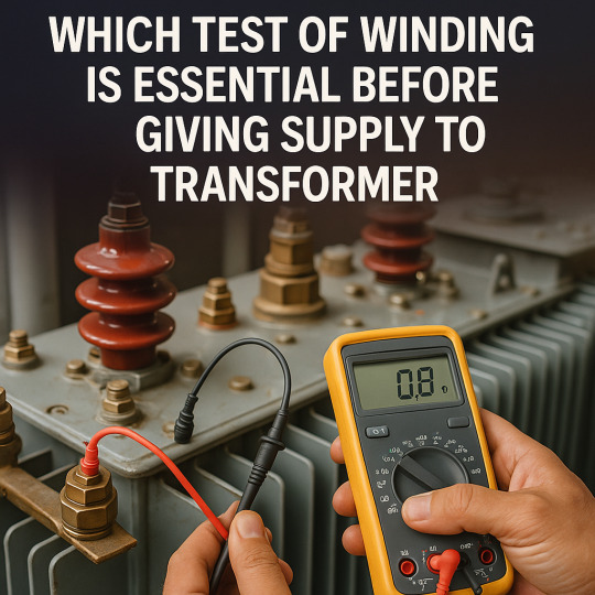
Which Test of Winding is Essential Before Giving Supply to Transformer
Before you energize any transformer, there's one big question to ask: which test of winding is essential before giving supply to transformer? This test ensures that the winding is not damaged, shorted, or improperly insulated. Skipping this step can lead to insulation failure, arcing, or even catastrophic damage.
Which Test of Winding is Essential Before Giving Supply to Transformer Let’s dive deep into the essential test you must perform, why it matters, how to do it, and what it tells you about the health of your transformer windings.
Importance of Winding Tests in Transformers
Before supplying power to a transformer, verifying the integrity of its windings is critical. These windings are responsible for transferring electrical energy between circuits. If they are damaged, the transformer may fail. Testing helps identify insulation weakness, short circuits, winding deformation, and moisture ingress. It is an important part of pre commissioning test of transformer to ensure safety and reliability.
Which Test of Winding is Essential Before Giving Supply to Transformer?
The most essential test is the Insulation Resistance (IR) Test. This test checks the insulation quality between: - Primary and secondary windings - Windings and the transformer core - Windings and the tank (earth) The IR test is simple, fast, and effective. It must be performed before applying any voltage. What Does the IR Test Detect? It helps detect moisture, dirt, insulation aging, and breakdowns. Any of these can lead to a fault if the transformer is energized without testing.
Recommended IR Values for Transformer Windings
Here is a typical table of minimum acceptable insulation resistance values: Transformer Voltage ClassIR Value Between Windings (MΩ)IR to Earth (MΩ)Below 1.1 kV>100>1001.1 kV to 11 kV>200>20033 kV>500>50066 kV and above>1000>1000 Note: Values depend on environmental conditions, such as humidity and temperature.
Test Instrument for Insulation Resistance Measurement
The IR test is conducted using a megger. It is a high-voltage insulation tester. Meggers usually operate at test voltages of 500 V, 1000 V, or 5000 V depending on transformer rating. Procedure for Performing IR Test - Isolate the transformer from the system. - Discharge all windings using grounding rods. - Connect the megger between the windings or between winding and ground. - Apply test voltage for one minute. - Record the insulation resistance value.#TransformerTesting, #WindingResistanceTest, #ElectricalSafety, #TransformerMaintenance, #PowerTransformer, #ElectricalInspection, #HighVoltageTest, #TransformerHealth, #ElectricalEngineering, #PreCommissioningTest, #InsulationResistance, #ElectricalTesting, #WindingCheck, #TransformerProtection, #SafeTransformerOperation Read the full article
#ElectricalEquipment#ElectricalSafety#EngineeringTests#HighVoltage#InsulationTesting#Maintenance#PowerSystems#Pre-SupplyChecks#transformertesting#TransformerWinding
0 notes