
Don't wanna be here? Send us removal request.
Statistics
We looked inside some of the posts by thmasterblogphicialandrewp and here's what we found interesting.
Average Info
Notes Per Post
0
Likes Per Post
0
Reblog Per Post
0
Reply Per Post
0
Time Between Posts
11 hours
Number of Posts By Type
Text
17
Last Seen Tumblr Blogs


Fun Fact
Tumblr was acquired by Yahoo for $1.1B in 2013.
Text
Project files link
https://drive.google.com/drive/folders/1ym0-VWdYq1R2ZGHJsz0OyNdMfDF7ucC7?usp=sharing
0 notes
Text
The Final Showcase
And what i have learned/ could do better.
youtube
while my final project did not work as intended. I think because the ground of the motors went through the Arduino it was triggering so sort of cutoff to the output.
I have learned a lot from this project. The things I have learned are-
the difference between brushed motors and brushless motors.
I have also learnt about electronic speed controllers and how they work for different motor types.
I have learned about PWM outputs and inputs as well as different methods to generate them.
I have learned about radio communication and Arduino structure.
I have also learnt to be more thorough in planning and implementation eg- controller PCB.
I have also expanded my soldering skills.
What could I have done better-
Do more research on the project before buying parts and permanently fixing parts together.
I could have saved a lot of time by using a different Arduino (Nano) however stubbornness and being cheap sabotaged me.
Not choosing a project because it looked cool.
Cleaner circuit diagrams and protecting them would have made construction easier.
wire management

enough said.
0 notes
Text
Failure?
After the failure I experienced with using the Multiwii code with my Arduino Leonardo drone I decided that I would have it work in some way. While the problems I had where mostly of my own design ie: atypical Arduino board, brushed motors. Some of the problems came from the design of the program with it being meant to suit a lot of equipment configurations it was difficult/ next to impossible to change any timer or pin assignments without interfering somewhere else in the code and because these parts where never meant to be altered no comments or explanations existed in the code or their website.
So, scraping Multiwii for now and determined to have my drone fly like a drone or at least look like it I have made this crude code to do so. This code would not allow auto leveling which most drones can disable anyway so not a big deal. It does allow for adjustment on all axis and can yaw. If I had started on this to begin with it may have been more complete and had more functions and tuning.
#include <SPI.h>
#include <nRF24L01.h>
#include <RF24.h>
#include <Servo.h>
//Define widths
int pwm_width_1 = 0;
int pwm_width_2 = 0;
int pwm_width_3 = 0;
int pwm_width_4 = 0;
int pwm_width_5 = 0;
int pwm_width_6 = 0;
int M3BR = 0;
int M5FR = 0;
int M6BL = 0;
int M11FL = 0;
int MNON = 0;
struct MyData {
byte throttle;
byte yaw;
byte pitch;
byte roll;
byte AUX1;
byte AUX2;
};
MyData data;
const uint64_t pipeIn = 0xE8E8F0F0E1LL; //Remember that this code is the same as in the transmitter
RF24 radio(13, 10);
void resetData()
{
//We define the inicial value of each data input
//3 potenciometers will be in the middle position so 127 is the middle from 254
data.throttle = 0;
data.yaw = 127;
data.pitch = 127;
data.roll = 127;
data.AUX1 = 0;
data.AUX2 = 0;
}
/**************************************************/
void setup()
{
pinMode(3, OUTPUT);
pinMode(5, OUTPUT);
pinMode(6, OUTPUT);
pinMode(11, OUTPUT);
pinMode(7, OUTPUT);
//Configure the NRF24 module
resetData();
radio.begin();
radio.setAutoAck(false);
radio.setDataRate(RF24_250KBPS);
radio.openReadingPipe(1,pipeIn);
//we start the radio comunication
radio.startListening();
}
/**************************************************/
unsigned long lastRecvTime = 0;
void recvData()
{
while ( radio.available() ) {
radio.read(&data, sizeof(MyData));
lastRecvTime = millis(); //here we receive the data
}
}
/**************************************************/
void loop()
{
recvData();
unsigned long now = millis();
//Here we check if we've lost signal, if we did we reset the values
if ( now - lastRecvTime > 1000 ) {
// Signal lost?
resetData();
}
pwm_width_1 = data.throttle;
pwm_width_2 = data.yaw;
pwm_width_3 = data.pitch;
pwm_width_4 = data.roll;
pwm_width_5 = data.AUX1;
pwm_width_6 = data.AUX2;
M3BR = pwm_width_1;
M5FR = pwm_width_1;
M6BL = pwm_width_1;
M11FL = pwm_width_1;
if(pwm_width_2 != 127){
if(pwm_width_2 < 127){
M3BR = M3BR + ((127 - pwm_width_2)/2);
M11FL = M11FL + ((127 - pwm_width_2)/2);
}
else{
M5FR = M5FR + ((pwm_width_2 - 127)/2);
M6BL = M6BL + ((pwm_width_2 - 127)/2);
}
}
if(pwm_width_3 != 127){
if(pwm_width_3 > 127){
M3BR = M3BR + ((pwm_width_3 - 127)/2);
M6BL = M6BL + ((pwm_width_3 - 127)/2);
}else{
M5FR = M5FR + ((127 - pwm_width_3)/2);
M11FL = M11FL + ((127 - pwm_width_3)/2);
}
}
if(pwm_width_4 != 127){
if(pwm_width_4 < 127){
M3BR = M3BR + ((127 - pwm_width_4)/2);
M5FR = M5FR + ((127 - pwm_width_4)/2);
}else{
M6BL = M6BL + ((pwm_width_4 - 127)/2);
M11FL = M11FL + ((pwm_width_4 - 127)/2);
}
}
if(pwm_width_5 = 1){
digitalWrite(13, HIGH);
}
if(pwm_width_5 != 1){
digitalWrite(13, LOW);
}
analogWrite(3, M3BR);
analogWrite(5, M5FR);
analogWrite(6, M6BL);
analogWrite(11, M11FL);
}
////////////////////////////////////////////////////////////////////////////////////////////////////////////////////
One benefit of all this is that it was very easy to incorporate my Nerf dart firer
0 notes
Text
Making it fly
Now that i have radio comunication and the motors attached i can add the flight code,
However because I was using an abnormal Arduino for this type of project (norm is Nano). I had to make some changes to the Multiwii code
The first change was altering the pin order in the output.cpp file. As I was unsure of which array was the correct one I changed them all.

I then altered the motor pins by using alternate timer/ PWM pin assignments
(OCR 0A, 4D, 3A, 0B)

This should have worked however some conflict with the variable atomicPWM_PIN5 (which worked and compiled till this point) meant that I was unable to finish the drone with the Multiwii program.
references-
https://www.arduino.cc/en/Hacking/PinMapping32u4
https://cdn.sparkfun.com/assets/resources/4/4/PWM_output_Arduino.pdf
https://www.youtube.com/watch?v=CPJHxQ6ALJc&t=209s
0 notes
Text
adding motors
The next step after establishing radio communications was to add the motors to the drone. As the Arduino can't supply the necessary current to all four motors, I used a transistor for each motor to act as a switch for the higher current. And used a signal from a PWM Arduino output to drive the gate.

after creating the motors and soldering them to the board i added two more motors to the top to fire a Nerf dart and used two part epoxy to affix all components to the frame of the drone.


0 notes
Text
Radio on the drone
The next step was to add the radio to the Arduino on the drone which had the same connections as the other Arduino other than input pin 9 being swapped with pin 13 as I pulled pad 9 off the Arduino. And then to use some test code to check that the controller signal was received.
#include <SPI.h>
#include <nRF24L01.h>
#include <RF24.h>
const uint64_t pipeIn = 0xE8E8F0F0E1LL;
RF24 radio(13, 10);
struct MyData {
byte throttle;
byte yaw;
byte pitch;
byte roll;
byte AUX1;
byte AUX2;
};
MyData data;
void resetData() {
data.throttle = 0
; data.yaw = 127;
data.pitch = 127;
data.roll = 127;
data.AUX1 = 0;
data.AUX2 = 0;
}
/**************************************************/
void setup() {
Serial.begin(250000);
resetData();
radio.begin();
radio.setAutoAck(false);
radio.setDataRate(RF24_250KBPS);
radio.openReadingPipe(1,pipeIn);
radio.startListening();
}
/**************************************************/
unsigned long lastRecvTime = 0;
void recvData() {
while ( radio.available() ) {
radio.read(&data, sizeof(MyData));
lastRecvTime = millis();
}
}
/**************************************************/
void loop() {
recvData();
unsigned long now = millis();
if ( now - lastRecvTime > 1000 ) {
resetData();
}
Serial.print("Throttle: "); Serial.print(data.throttle); Serial.print(" "); Serial.print("Yaw: "); Serial.print(data.yaw); Serial.print(" "); Serial.print("Pitch: "); Serial.print(data.pitch); Serial.print(" "); Serial.print("Roll: "); Serial.print(data.roll); Serial.print(" "); Serial.print("Aux1: "); Serial.print(data.AUX1); Serial.print(" "); Serial.print("Aux2: "); Serial.print(data.AUX2); Serial.print("\n");
}
youtube
http://www.electronoobs.com/eng_arduino_tut37_code2.php
http://www.electronoobs.com/eng_robotica_tut5_2.php
https://starter-kit.nettigo.eu/2014/connecting-and-programming-nrf24l01-with-arduino-and-other-boards/
https://www.youtube.com/watch?v=7rcVeFFHcFM
0 notes
Text
Now for control
My next step in creating this drone was to create the radio controller for the drone. I felt that this step should come before any more of the flight programs build so that when the drone is programed, I can test changes before having to add extra code to discover these problems.
For the radio controller I used the body of an old SYMA drone radio controller, an Arduino Leonardo and the potentiometers/ buttons that came with the old body.
The first step was to disassemble the old controller so that I could examine the layout of the PCB and how I would place objects.


After examining I have concluded that with the Arduino board on the backside of the PCB, I will be unable to reattach the back-plate/battery bay, so I must use an alternate plan for power. The solution was to use 2 x 3.7v Lipo cells in series to provide power. These can then be taped into a well of space. After soldering the battery live to the switch of the old board, I cut all the old PCBs traces. And then I soldered colour coded wires onto the inputs of the potentiometers and combined the grounds and lives. I then added this code to test the potentiometers.
struct MyData {
byte throttle;
byte yaw;
byte pitch;
byte roll;
byte AUX1;
};
MyData data;
void resetData() {
data.throttle = 0;
data.yaw = 127;
data.pitch = 127;
data.roll = 127;
data.AUX1 = 0;
data.AUX2 = 0;
}
/**************************************************/
void setup() {
Serial.begin(250000);
resetData();
/*
radio.begin();
radio.setAutoAck(false);
radio.setDataRate(RF24_250KBPS);
radio.openReadingPipe(1,pipeIn);
radio.startListening();*/
}
/**************************************************/
unsigned long lastRecvTime = 0;
void recvData() {
while ( radio.available() ) {
radio.read(&data, sizeof(MyData));
lastRecvTime = millis();
}
}
/**************************************************/
void loop() {
recvData();
unsigned long now = millis();
if ( now - lastRecvTime > 1000 ) {
// Signal lost? resetData();
}
Serial.print("Throttle: "); Serial.print(data.throttle); Serial.print(" "); Serial.print("Yaw: "); Serial.print(data.yaw); Serial.print(" "); Serial.print("Pitch: "); Serial.print(data.pitch); Serial.print(" "); Serial.print("Roll: "); Serial.print(data.roll); Serial.print(" "); Serial.print("Aux1: "); Serial.print(data.AUX1); Serial.print(" "); Serial.print("Aux2: "); Serial.print(data.AUX2); Serial.print("\n");
}


///////////////////////////////////////////////////////////////////////////////////////////////////////////////////////////////
This didn't work the inputs all stayed low.
after trouble shooting and checking all the connections and re-soldering twice on dogie joints (for 4hrs). I discovered that the old board traces still connected the switch to the processor so it was drawing all of the power. I removed it with some pliers. after this i retried the code and it still did not work as it should have.


At first, I thought that this may be a problem with the relatively low voltage supply for a Leonardo, or a problem with the reference voltage. I however turned after more testing that either the old traces where not properly disconnected, or I missed some likely because the traces where weird with the dark lines being separation between traces and not traces themselves as I had originally believed. Because of this the sample pin of the potentiometers was tied to ground at the same time as to the analogue inputs. After being perhaps a tad aggressive with an Exacto knife and reassembling the connections the code worked and outputted 4 values from 0-1023 relative to potentiometer position. I then looked at attaching the nrf24l01 to give my transmitter transmitter-ness. The tutorial's that I looked at for this step used the Arduino Nano and this was a problem as the architecture and the pin layouts are different so I had to do some additional research to find out which pins I should use. The information I found nettigo(2014) was for the Uno however the Leonardo shares the same ICSP pins so the info was applicable to my build. I then soldered the radio to the board.
nettigo. (2014) Connecting and programming nRF24L01 with Arduino and other boards. Available at: https://starter-kit.nettigo.eu/2014/connecting-and-programming-nrf24l01-with-arduino-and-other-boards/ (Accessed: 20/04/2020).


After all of this i taped the cells in place and zip tied the Arduino in place (university board so that was only way to secure it).

0 notes
Text
Assembling the fpv goggles
After the parts arrived I cut slots in a cardboard box and then attached the screen to the rest and then taped it in place. A missing connector required me to direct solder the battery pack and remove a battery to break the circuit. The fpv camera was also attached to the Arduino and the drone body was tested for space.


I attempted to use a built in switch so the Arduino could be turned on and off but it was broken and a hole need to be melted in the side so the camera would have clearance to be in the drone and under the Arduino.


0 notes
Text
The Accelerometer
The first step in testing was to connect the accelerometer to the Arduino and use the Multiwii program to check that the board worked and find the forward axis (edit: discovered the factory markings later) to do this I had to connect the gyro to the scl and sda pins I could then activate the right parts of the Mutiwii config to use these parts


youtube
code changed in multiwii config.h


The x and z axis were changed so that the accelerometer could be better placed withing frame.
A new radio sum order was also added to fit my radio setup


0 notes
Text
The parts arrive
After all of the parts had arrived I began making preparations for building. These preparations include drawing out a circuit diagram. Problems encountered later in the build required a reworking/drawing of component positions and rewiring this includes pad 9 detaching and the Leonardo board requiring the use of different pins for the NRF24l01 radio.
I also downloaded both the NRF24 libary and the Multiwii program
links:
https://github.com/nRF24/RF24
https://github.com/multiwii
I also took the step to remove the plastic headers and metal forks from the pins so thatIi could direct solder and both save space and have a more reliable connection

0 notes
Text
An addition to the plan
After looking at the original video that inspired this build, while waiting for parts to arrive. I then decided to add a first person view camera to the drone. This addition would also necessitate a FPV headset. and continuing with the theme of DIY and cost saving I found a kit that was easy to put together and a camera to put in the drone.
links:
https://www.banggood.com/RX5808-5_8Ghz-48CH-FPV-Receiver-with-480320-5-Inch-HD-Display-Snow-Screen-Monitor-DIY-For-FPV-Goggles-p-1309235.html?utm_campaign=5635792_1001216&utm_content=1081&p=CG24181822629201506N&cur_warehouse=CN
https://www.amazon.co.uk/gp/product/B06XK9KX1Z/ref=ppx_yo_dt_b_asin_title_o07_s00?ie=UTF8&psc=1

0 notes
Text
Project : gathering info
Before further continuing my project, I had to first do some research onto the topic and how all of the components are used as well as how my particular project would work. My lecturer pointed me in the direction of a YouTube channel with some tutorials on building drones from Arduino boards. https://www.youtube.com/channel/UCjiVhIvGmRZixSzupD0sS9Q . This channel had a set of videos for both brushless and brushed drones with links to a website for code and templates. One problem I found consistently with this channel was a lack of explanation behind the instructions. As only a single combination of board and radio were shown and his example/useable code only accounted for this. This was a problem as I used a different board and chip structure. The tutorials were also reused in some parts leading to a hard time watching them in order or finding specific information.
Link to code and website :
https://www.electronoobs.com/eng_arduino_tut23_parts1.php
https://www.electronoobs.com/eng_arduino_tut23_sch1.php
http://www.electronoobs.com/eng_robotica_tut5_1.php
And YouTube playlists :
https://www.youtube.com/playlist?list=PLsR1AO4QH1AztoVVaw4sKqnq0RcA3rO7v
https://www.youtube.com/playlist?list=PLsR1AO4QH1Azezx2KBeHrlakiOjN65BGX
after looking at the tutorials i bought a list of parts:
-5 IRFZ44N Transistor Mosfet’s
-4 SR5100 Schottky Diodes
-2 NRF24L01 wireless Transceivers
1 GY-521 MPU-6050 3 axis accelerometer
4 3.7v 1000mAh rechargable batteries
1 - resistor kit including 10Kohm resistors
1 Arduino Leonardo micro-controller
the design for the circuit diagram is here (some parts where changed later to fit changes in information available to me).

0 notes
Text
Project starting and initial research
When I began this project, I first started by finding any old parts I had and taking inventory of what I had and what I would at minimum need for the project. I found two old drones and one remote controller as well as some spools of single and multi-strand electrical wire along with electrical tape of different colours.


As it would have been necessary later, I decided to take apart the drone body's and remove and inventory the parts before continuing.
After determining that the only part from the flight controller that was useful was the battery connector I de-soldered it and the flight controller. I then looked at the existing motors and realised that they were DC motors. I used the Arduino board to test the polarity and spin direction of each input wire. The would-be live wire of each motor had a small piece of electrical tape applied.
0 notes
Text
Final project first look and concept
This week we were given our assignment of creating a final project for our module. After looking at some examples and brainstorming a few ideas I found them to either be too simple for my liking or required me to buy to many parts to keep the cost as low as I would have liked. Later after watching a video on youtube ‘I Built a REAL Nerf Attack Drone!’ (Corridor Crew, 2020), I remembered that I had an old drone and multiple radio controllers I could strip for parts which would keep the cost of the project down and would allow me to challenge myself by building a drone from irregular and non-standard parts. The temptation of adding a shooting mechanic also held a draw but was secondary.
youtube
Corridor Crew(2020) I Built a REAL Nerf Attack Drone!. Avalible at https://www.youtube.com/watch?v=8RKy_i2h_j8&t=944s (Accessed: 13 March 2020)
0 notes
Text
Week 4
In this week the main objective was to introduce stepper motors. In this session I used an Arduino Leonardo, a stepper motor and connector, a breadboard, and a potentiometer.
The first test that I carried out with the stepper motor was to use the default stepper motor code with a potentiometer. This code increased the stepper motors speed of rotation when the potentiometer this worked well.
#include <Stepper.h>
Const int stepsPerRevolution = 200;
Stepper myStepper(stepsPerRevolution, 8, 9, 10, 11);
Int stepCount = 0;
Void setup(){ }
Void loop(){
Int sensorReading = analogRead(A0);
Int motorSpeed = map(sensorReading, 0, 1023, 0, 100);
If(motorSpeeed > 0) {
myStepper.SetSpeed(motorSpeed);
MyStepper.step(stepsPerRevolution / 100)
}
}
youtube
The next test was to see if I could turn the stepper motor proportional to the potentiometer while this did work it showed flaws in the fact the scale of change was to small and the potentiometer would only effect changes when moving in one direction this could be improve but I would have to look into the operation of stepper motors more.
#include <Stepper.h>
#define STEPS 200
Stepper myStepper(STEPS, 8, 9, 10, 11);
Int previous = 0;
Void setup(){
Stepper.SetSpeed(30);
}
Void loop(){
Int initial = analogRead(A0);
Int val = map(initial, 0, 1023, 0, 100);
Stepper.step(val – previous);
Previous = val;
}
youtube

0 notes
Text
Week 3
In this week we explored how to use servomotors. Servomotors are motors that use an analogue signal to determine the axis position and its speed.
In these experiments we used a potentiometer, servo and an Arduino to cause the servo to move/ spin when the potentiometer was adjusted. This was relatively simple just combining the knowledge from week 2 of analogue ins and outs with a basic example from the Arduino program.
youtube
After this I attempted to get the servo to follow a light source by replacing the potentiometer with the LDR potential divider from week 1. And adding code so that if the light level changed the arm would try each direction to see if it further deviated from the strongest reading and would then move till the reading stopped climbing. This however proved an over complicated way to do it and unachievable in the class time period. However, a separate classmate managed to achieve it by having the arm rotate in one direction till the reading was highest.
#include <Servo.h>
Servo myservo;
int Val; int Val1; int Val2; bool M1; bool M2; void setup() { myservo.attach(9); }
void loop() { val = analogRead(A0); val = map(val, 0, 1023, 0, 180); if(val != Val1){ do{ if(val < val1 && M1 == falsue){ val2 = val; val++; myserbo.write(val); val = analogRead(A0); if(val < val2){ M1 = true; } else{ M2 = true; } } if(val < val1 && M2 == false){ M2 = true; }else{ M1 = true; } if(val > val1){val1 = val;} }while(val != Val1); } val1 = val; M1 = false; M2 = false }

0 notes
Text
Week 2 analogue inputs
This week we experimented with using analogue inputs and outputs on our Arduino boards. The Arduino programmer comes with some example analogue input templates which where helpful in learning how to read the inputs and output readings too.
The goal for this lesson was to incorporate the use of analogue readings into a digital program. This is done by using an analogue to digital converter, this reads different levels of voltage from 5V – 0V and converts them to an integer value. The Arduino board has a 10-bit ADC so you can read 1024 different levels or every 4.88mV or 0-1023.
The main objective of the experiment this week was to incorporate an LDR resistor (light dependent) which changes resistance in response to light hitting it. This resistor increased in resistance as less light hit. The LDR was incorporated by using it and a second resistor to form a potential divider.
This works by taking the voltage value from in-between the two resistors and reading it with the Arduino analogue pin. When the LDRs resistance changes the balance of voltage across each resistor changes. If you know the exact resistance value of the resistors this equation can give the voltage across each resistor.

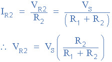
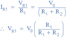
These values would obviously change when the light level changes so the equation is more useful to get a stable voltage from static resistors or to check that the size of the LDR and resistors are proportionately correct at the LDR’s mid-value.
My experiment changes the brightness of the LED in response to a change in light level.
youtube
int a; int out; void setup() { // put your setup code here, to run once: pinMode(13, OUTPUT); }
void loop() { a = analogRead(A0); out = map(a, 0, 1023, 0, 255); analogWrite(13,a); }
The next step I took after this was to use a potentiometer as the second resistor. A potentiometer is essentially an all in one potential divider. This allowed me to adjust the sensitivity of the system to the LDR Dynamically and I used this to adjust the speed that an LED blinked.
youtube
int sensorPin = A0; int ledPin = 13; int sensorValue = 0; void setup() { // put your setup code here, to run once: pinMode(ledPin, OUTPUT); }
void loop() { sensorValue = analogRead(sensorPin); digitalWrite(ledPin, HIGh); delay (sensorValue); digitalWrite(ledPin, LOW); delay(sensorValue); }
Separating the LDR and Potentiometer onto different readings would have allowed me to adjust more functions then just flash speed.
I made a final change by substituting the Potentiometer with a push to make button same concept
youtube

0 notes