
Don't wanna be here? Send us removal request.
Statistics
We looked inside some of the posts by viola-tang-blog and here's what we found interesting.
Average Info
Notes Per Post
1
Likes Per Post
1
Reblog Per Post
0
Reply Per Post
0
Time Between Posts
3 days
Number of Posts By Type
Text
9
Last Seen Tumblr Blogs


Fun Fact
Post activity is at the highest at 4:00 pm EDT; notes peak at 10:00 pm EDT.
Text
Brief Introduction of Optical Line Protection
The particularity of optical transport network (OTN) requires that optical transmission equipment and lines must have high stability and security. However, problems like optical fiber damage, line interruption, and equipment power down always severely affect the security of OTN. Then, what we should do to protect OTN security? Luckily, the appearance of optical line protection (OLP) system has provided one of the effective solutions. . This article will have a brief introduction of OLP and its working methods.
What Is Optical Line Protection?
Optical line protection (OLP) is a device used in pairs to protect network transmission lines. When the power value of a working fiber is lower than a certain lever, OLP can automatically switch from the working fiber route to another spare fiber route by real-time monitoring. It is usually used with devices such as DWDM mux, EDFA, and DCM to achieve fiber expansion in optical transport network. Due to its high security and service quality, OLP is widely used for protecting backbone and important business line.

Common Methods of Optical Line Protection
In optical transport network, there are two common types of optical line protection: OLP 1:1 system and 1+1 system, which can meet requirements of different applications. The following part will introduce the working methods of OLP 1:1 and OLP 1+1.
OLP 1:1
The 1:1 optical line protection system adopts a selective transmitting and selective receiving method. There are two fiber routes: primary path and secondary path. The optical power sent from Tx port will be normally transmitted through the primary path. When Rx port detects the power valve of primary path is decreasing, OLP 1:1 system will automatically switch the transmitting power and receiving power from the primary path to secondary path. This OLP 1:1 system has low insertion and high security, which is mainly suitable for trunk/local OTN and dedicated line customers.

OLP 1+1
Unlike OLP 1+1 system, optical line protection 1+1 system is based on dual transmitting and selective receiving method, which means the power can be transmitted through two paths at the same time. The optical power from Tx port will be divided into two equal parts on the primary path and secondary path. No matter what fault happens in single Tx or Rx direction of neither path, the two paths are still in use. This OLP 1+1 system has low cost and fast switching speed. However, because of its high insertion loss, OLP 1+1 is more suitable for short distance transmission with large surplus of the line.

Advantages of Optical Line Protection
From the introduction above, we can know that OLP can realize optical power monitoring and automatic switching. The following part will focus on these two advantages.
Real-Time Power Monitoring
OLP system can provide real-time monitoring of the primary and secondary optical fibers, which can effectively avoid the simultaneous block of the two optical fibers. This real-time power monitoring improves the transparency and security of optical transport network.
Automatic Switching
When the current optical power is lower than normal value on the main fiber, the system will automatically switch to the secondary available fiber, so as to ensure the smooth flow of the service. It can shorten the interruption time and improve the efficiency of maintenance.
Conclusion
Like the devices of DWDM mux, EDAF, and CDM, OLP is also an essential part of optical transport network. OLP has established a strong protection mechanism in place for network, which makes optical transport network with no-block, high reliability, safety, and high anti-disaster strength.
0 notes
Text
Overview of CWDM vs DWDM
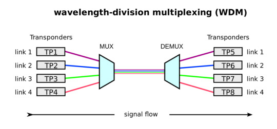
As we know, WDM (wavelength-division multiplexing) is a technology that can multiplex a number of optical carrier signals into a single optical fiber by using different wavelengths of laser light. Since there is a tremendous demand for high bandwidth, WDM becomes popular in the market. There are two key types of WDM technologies: CWDM (coarse wavelength division multiplexing) and DWDM (dense wavelength division multiplexing). Then, what are they? What’s the difference between them? This article will have a brief overview of CWDM vs DWDM to help you understand the differences between CWDM and DWDM technology.
What Is CWDM Technology?
CWDM (coarse wavelength division multiplexing) is a wavelength multiplexing technology for cities and access networks. The word “coarse” means the wavelength spacing between channels is relatively large. In general, CWDM has 18 different channels with a wavelength range from 1270 nm to 1610 nm. Because of the high data rates and low cost, CWDM is widely used in large campuses and data centers. Hence, it has become the preferred method for increasing the bandwidth of metro and optical access networks at a low cost.

What Is DWDM Technology?
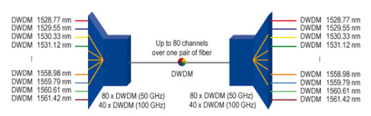
DWDM is an optical multiplexing technology used in fiber optics to increase the bandwidth, which resembles CWDM technology. The word “dense” here means the wavelength channels are very close to each other. According to ITU regulations, DWDM has 100GHz (0.8nm) wavelength spacing for 40 channels or 50GHz (0.4nm) spacing for 80 channels. Because of its ability to handle so much data, DWDM is widely used in telecommunications and cable companies and becomes an integral part of their core networks gradually.
CWDM vs DWDM: What Are Their Differences?
Both CWDM and DWDM use multiplexed wavelengths of laser light to increase bandwidth capacity. However, they still have a lot of differences given the following aspects: channel spacing, transmission distance, modulation laser and cost. Just read on to find the details.
Channel Spacing
From the words “coarse” and “dense”, we can see the difference in channel spacing that CWDM has a wider spacing than DWDM. CWDM can provide 18 wavelengths (from 1270 nm to 1610 nm) with the channel spacing of 20 nm. While DWDM can carry 40, 80 or even 160 wavelengths (from 1563.86 nm to 1528.77 nm) with a narrow wavelength spacing of only 1.6, 0.8 or even 0.4 nm. It is simple to see that DWDM has a better performance than CWDM when transmitting a greater number of multiplexed wavelengths on a singer fiber.
Transmission Distance
DWDM technology is able to have a long transmission by keeping the wavelength highly integrated. The amplified wavelengths can make DWDM suffer less interference over a larger run of cable. Unlike DWDM technology, CWDM can’t travel unlimited distance as the wavelengths are not amplified. Usually, CWDM can transmit data up to 160 km.
Modulation Laser
DWDM technology uses the cooling laser, which is a technology that atomic and molecular samples can be cooled down to near absolute zero. Conversely, CWDM technology uses the uncooled laser, which can’t ensure better performance, higher safety, and long life span like DWDM.
Cost
Generally, the price of DWDM is four or five times higher than that of CWDM. The higher cost of DWDM mainly contributes to cooling laser technique which can realize the temperature tuning. But nowadays, as DWDM technology becomes more and more popular, the price of DWDM transceiver becomes cheaper than CWDM transceiver.
A detailed comparison between CWDM and DWDM technology is in the table below.

Conclusion
From the introduction of CWDM vs DWDM, we know that CWDM and DWDM are two technologies based on WDM technology with different wavelength patterns and applications. Usually, CWDM costs less and its performance is far behind DWDM. Both the cost and requirement should be taken into consideration. You’d better think twice before choosing a CWDM or DWDM system.
0 notes
Text
Nowadays, 10GBASE-T has been provided as an add-in card in switches, servers, and network interface cards (NICs). It has many advantages like low cost and easy immigration from 1GBASE-T to 10GBASE-T. This article will introduce what 10GBASE-T technology is and how to connect two 10GBASE-T ports or connect a 10GBASE-T port with an SFP+ port, which may help you have a good understanding of 10GBASE-T.
What Is 10GBASE-T Technology?
10GBASE-T is a type of Ethernet signaling which provides 10G connections over unshielded or shielded twisted pair cables with distances up to 100 meters. A 10GBASE-T port is an RJ45 interface, which means it can be connected to another RJ45 port just with an Ethernect patch cable. And more importantly, the 10GBASE-T cable infrastructure can also be used with 1000BASE-T, allowing for a gradual upgrade from 1000BASE-T, which means it can use auto-negotiation to choose which speed to use. For example, 10GBASE-T copper modules can negotiate automatically to 10 Mbps, 100 Mbps, 1 Gbps, 2.5 Gbps, 5 Gbps, and 10 Gbps, which is the highlight of this product. In fact, 10GBASE-T connection can be simply divided into two types: connection between two 10GBASE-T ports and connection between a 10GBASE-T port and an SFP+ port.

Connection Between Two 10GBASE-T Ports
There are many cases of the connection between two 10GBASE-T ports like connecting two switches with 10GBASE-T ports, two 10GBASE-T servers, and a sever to a NIC with 10GBASE-T ports. For these cases above, it is quite simple to connect them, you just need to connect them with a cable like placing the plug into its mating socket.

Figure 2: S5850-48T4Q 48-Port 10GBase-T L2/L3 Data Center Tor/Leaf Switch.

Figure3:PCIe 2.1 x8 Dual Copper Port 10GBase-T Ethernet Network Interface Card
As for 10GBASE-T cables, there are many different cables to choose like Cat6, Cat6a, Cat7, and Cat8. How to choose them? It depends on many factors like transmission distance, cost, and bandwidth. In general, when transmitting 10 Gbps, Cat6 can support the distance between 37 and 55 meters, while Cat6a, Cat7 and Cat8 can support up to 100 meters. Cat8 cable has the highest cost than Cat6, Cat6a and Cat7. And it can support a speed of 25 Gbps or even 40 Gbps, while Cat6, Cat6a and Cat7 can support the speed of 10G maximum. You can choose the most suitable cable according to the factors above.
Connection Between a 10GBASE-T Port and an SFP+ Port
If connecting two devices with different ports, for example, connecting a switch with 10GBASE-T ports to a server with SFP+ NIC or connecting a switch with SFP+ ports to a server with 10GBASE-T fixed ports, what should we do? In these cases, we should prepare a 10GBASE-T SFP+ module which has an RJ45 interface and can be plugged into an SFP+ port. Then, use the Cat6a or Cat7 cable to connect the RJ45 interface of the module to another device with a 10GBASE-T port. The distance between two devices is usually limited by the 10GBASE-T SFP+ module, which supports 10GBASE-T for only up to 30 meters.

Figure 4: Cisco SFP-10G-T-S Compatible 10GBASE-T SFP+ Copper RJ-45 30m Transceiver Module
Conclusion
10GBase-T is backward compatible with fast Ethernet and Gigabit Ethernet. It is necessary to know the requirements for 10GBASE-T connection, which will help you have a correct cognition about 10GBASE-T.
0 notes
Text
As the central nerve of the whole data system, network switch becomes more popular. To satisfy different sizes of networking deployment, there are various types of Ethernet switches. This article will introduce S58/S80 series switches and their login steps.
Basic Information of Seven S58/S80 Series Switches
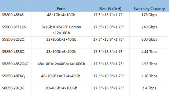
There are seven types of S58/S80 series Gigabit switches: S5800-48F4S, S5800-8TF12S, S5850-32S2Q, S5850-48S6Q, S5850-48S2Q4C, S5850-48T4Q, and S8050-20Q4C. All of them are managed switches which can be managed by CLI/Web/Telnet, etc. Nowadays, they are widely applied for data center and enterprise network. The following part will show a table to introduce the basic information of seven S58/S80 series switches, including ports, size, and switching capacity.
Guide to Connect Computer and S58/S80 Series Switches
First, you have to prepare these products: an S58/S80 series switch, an RJ45 to female RS232 converter cable, a male RS232 to USB converter cable, and a computer. We mainly have three steps to achieve the connection between a computer and S58/S80 series switches.

Step 1
Connect the console port of the switch using the RJ45 to female RS232 converter cable

Step 2
Connect the female RS232 connector with the male RS232 connection of the two converter cables.

Step 3
Connect the computer using the male RS232 to USB converter cable. After completing the above steps, your computer and switch will be physically connected.
Steps of Logging in S58/S80 Series Switches
Step 1
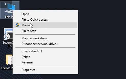
Right click on “My Computer”, left click on “Manage’’.

Step 2
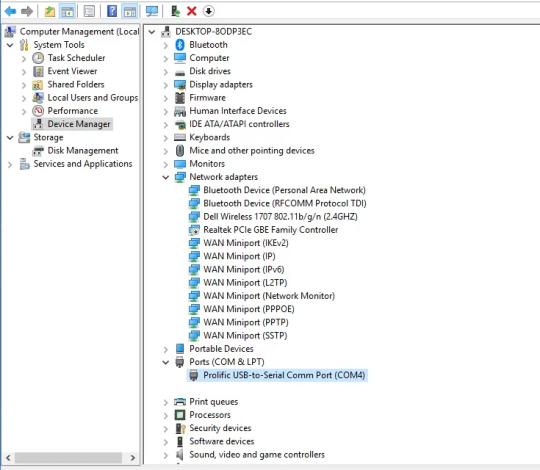
Click on “Device Manager”, and we can see a serial device unrecognized. Then, right click on it, choose “Update driver”.
Step 3
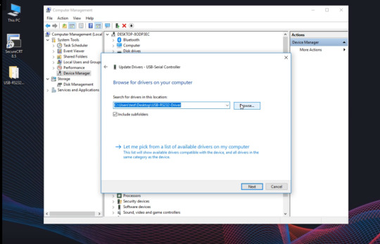
Choose “Browse for drivers on your computer”, and select the path where the driver is stored from the local computer (driver is placed on the desktop in this example). Then, click on “Next” and wait.
Step 4
Now, we can see the Com number after the installation is 4.

Step 5
Double click on the CRT to open the control software. Then, select the “protocol” as “Serial”, the “Port” as “COM4”, the “Baud rate” as “115200”, and click on “Connect”.

Step 6
Now, we can see a green exclamation mark displayed in the upper left corner, indicating that the com port can be used. Then, press Enter and appear the word “Switch”, which means you have signed in.

Step 7
Input “enable” to enter the privileged mode, input “configure terminal” to enter the configuration mode. If you want to use your own IP, you should input “no management IP address”, if you want to continue to use the switch's default IP acquisition method, you can skip this step.

Step 8
Input “management IP address 192.168.1.1/24 gateway 192.168.1.254” to set the “management port IP address” as “192.168.1.1”, the “mask” as “24 bits”, the “gateway” as “192.168.1.254”. Congratulations! At this point, you have completed all the steps for the switch login.
0 notes
Text
How to Extend 40G Connection to 48 km With DWDM Solution
As the data accumulated by users and enterprises increases, the demands for storing and accessing data are becoming larger, making people pursue higher data capacity and data transmission. Nowadays, many data centers and enterprises are equipped with 40G switches, but the link distance of 40G switch becomes a big challenge.
As we know, 40G QSFP+ transceiver has a maximum transmission distance of only 40 kilometers. If the distance between two data centers is more than 40 km, what should we do? For example, there’s a need to connect two 40G switches located in two sites. The minimum distance between them is 48 km, which will use two fibers of a dark fiber link. In this case, we usually use DWDM to extend the transmission distance.
DWDM Solution of 40G Connection Over 48 km
This DWDM solution mainly applies WDM transponder OEO, DWDM Mux/Demux, and 10G DWDM SFP+ to extend the transmission distance.

What Is This DWDM Solution Like?
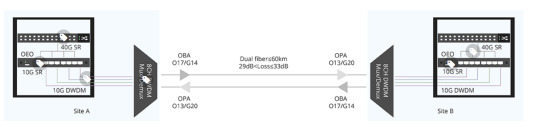
In this DWDM solution, in order to extend 40G QSFP+ connection distance, one 40G SR4 QSFP+ transceiver installed on the 40G switch is linked with four 10G SR transceivers by MTP-LC harness cables. In this way, one 40G optical signal can be divided into four 10G signals, and then OEO (Optical- Electrical- Optical) converts them to the corresponding DWDM wavelengths to four 80km 10G DWDM SFP+ modules. Then, connect 10G DWDM SFP+ modules on the OEO repeater and DWDM Mux/Demux by using LC duplex patch cables. In the next step, the 8ch DWDM Mux/Demux will combine the four 10G DWDM signals of different wavelengths into one single fiber and the signal after multiplexing is transmitted through dark fiber. In this way, 40G QSFP+ distance can be extended up to 80km with the use of DCM (Dispersion Compensation Module), BA (Booster Amplifier) and PA (Pre-Amplifier).
Why This DWDM Solution?
Of course, we can't only look at the present design, but also have to make long-term plans, thinking about the future needs of customers.
Meet Demands for Expansion
DWDM Mux/Demux can combine 10G signals of different wavelengths on one single fiber, which is the best solution to increase network capacity and save cost. In this DWDM solution, we choose the 8ch DWDM Mux/Demux instead of 4ch, because 8ch DWDM Mux/Demux can provide customers with later expansion. These two sites is a 40G point to point link, which can fully realize two 40G dual fiber connection up to 80km with 8ch.
Low Link Loss
In order to ensure the quality of signal, it is necessary to control the single-wave output power of BA (Booster Amplifier) below +8 dB, and the single-wave input power of PA (Pre- Amplifier) is controlled above -25 dB. DWDM solution is suitable for the point to point link whose link loss is from 29 to 33 dB. When the link loss reaches the maximum value of 33 dB, there is still a margin of 3 dB.
FAQs
Q: How to put OBA and OPA?
Optical Booster Amplifier (OBA) should be put behind the optical transmitter MUX while in front of the optical fiber line, which can increase the power of the transmitted light. And in order to amplify the weak optical signal, the Optical Pre-Amplifier (OPA) should be placed before the optical receiver Mux but after the optical fiber line.
Q: Why do we use OEO?
OEO is an optical media converter which allows connection between fiber-to-fiber Ethernet equipment, serving as fiber mode converter, or as fiber repeater for long-distance transmission. In this DWDM solution, we need OEO to convert common 10G signals to the corresponding DWDM wavelengths, so that they can transmit in the DWDM Mux/Demux.

Conclusion
DWDM solution provides a good way to solve the distance problem, making 40 km transmission distance is not the limit of 40G connection anymore. If you want to know more information, please reach us via [email protected].
0 notes
Text
Nowadays, switches are used almost everywhere from SOHO (Small Office/Home Office) to major ISPs (Internet Service Providers). Layer 2 and Layer 3 switches are the most common types of switches in our lives. Both of them have been widely used in a greater variety of commercial applications and even advanced residential projects. This article will help you understand the difference between Layer 2 and Layer 3 switch.
Definition of Switch
In a network, switch is a hardware device that filters and transfers network packets from one network device to another, like computers and routers. Hence, it is widely used in local area network (LAN) to send each incoming message by looking at their physical address, such as MAC address. In fact, a switch is commonly considered as a multiport network bridge that uses hardware addresses to process and transfer data at the data link layer (layer 2). Some switches can also process data at the network layer (layer 3) by combining routing functions. Recommend you reading this article to know what are different layers:TCP/IP vs. OSI: What’s the Difference Between the Two Models
Layer 2 and Layer 3 Switches: What Are They?

Layer 2 Switch
A Layer 2 switch basically does switching only, which means that it operates using a device's MAC address to redirect data packets from the source port to the destination port. During the manufacturing process, switches operating at Layer 2 are very fast because they are just sorting MAC addresses at a physical layer.
Layer 3 Switch
A Layer 3 switch uses IP addresses that identify locations on the network. A location can be a LAN workstation, a site in a computer’s memory, or even a different packet of data traveling through a network. It has fast switching capabilities and high port density, making it route data packets without producing extra networking hops.
Layer 2 vs. Layer 3 Switch
Both of Layer 2 switches and 3 switches have their unique characteristics. The following part will compare Layer 2 switches and Layer 3 switches from three aspects: speed, function, and address.
Speed
Usually, the switch operates at Layer 2 takes less time than Layer 3. Because all that a Layer 2 switch does is assigning MAC addresses to reroute packets from source port to destination port. In the meanwhile, a Layer 2 switch only takes a little time to examine data packets before finding the best possible route to send packets to their destination port, but a Layer 3 switch will take more time to examine.
Function
A Layer 2 switch can only switch packets from one port to another, which means devices only can communicate within the same network. Instead, a Layer 3 switch can both switch and route, which means devices can communicate within as well as outside the networks.
Address
A Layer 2 switch uses devices’ MAC addresses to redirect data packets and doesn’t interact with any higher layer addresses, such as an IP. Conversely, a Layer 3 switch can do static routing and dynamic routing, which includes IP and virtual local area network (VLAN) communications.

Conclusion
Generally, a Layer 2 switch has been used for small networks, while a Layer 3 switch has primarily been used in data centers and large campus network environment. And, as networks move toward greater complexity, Layer 3 switches will become much more of necessity, especially for larger networks. To choose a Layer 2 switch or a Layer 3 switch, that may depend on your actual demands.
0 notes
Text
Common Types of 10G and 100G fiber optic transceiver
With the development of Internet, the demand for higher bandwidth is rising rapidly. As an important part of optical network equipment, fiber optic transceiver is becoming more and more popular. There are many types of fiber transceivers given different transmission rates from 0.5 Mbps to 200 Gbps. This article will cover the two most commonly used fiber optic transceiver types, 10G transceiver and 100G transceiver, and introduce their sub-classifications respectively.
What is Fiber Optic Transceiver?
A fiber optic transceiver is a device that uses fiber optical technology to transmit and receive data. It has a transmitter and a receiver that are combined and share common circuitry or a single housing. Moreover, it also has electronic components for adjusting and encoding the data into light pulses as an electrical signal. When transmitting data, transceivers always make use of light sources like VSCEL, FP and DFB lasers, and when receiving light sources, they will make use of photodiode semiconductors.
Overview of 10G Fiber Optic Transceiver
Definition of 10G Fiber Optic Transceiver
10G fiber optic transceiver is designed for 10G or 10Gbps data transmission applications including 10 Gigabit Ethernet, 10 Gbps Fibre Channel, and Synchronous optical networking (SONET).
Classification of 10G Fiber 0ptic Transceiver
10G fiber optic transceiver mainly includes 10G XENPAK, 10G X2, 10G XFP, and 10G SFP+. The following part will introduce them in turn.
10G XENPAK Transceiver
10G XENPAK fiber optic transceiver was the very first MSA (Multi-Source Agreement) for 10GE coupled with the biggest form factor. It allows all optical ports defined in IEEE 802.3ae, supporting speeds of 10.3 Gbps, 9.95 Gbps or 3.125 Gbps.

10G X2 Transceiver
0G X2 fiber optic transceiver defines a smaller 10Gbps pluggable fiber optic transceiver optimized for 802.3ae Ethernet, ANSI 10GFC (10 Gigabit Fibre Channel) and other 10 Gigabit applications. Originally centered on a 10km fiber link, the X2 transceiver is very suitable for telecom switches, standard PCI (peripheral component interconnect) server, and storage connectivity.

10G XFP Transceiver
10G XFP fiber optical transceiver is actually a standard for transceivers that are used in high-speed computer networks and telecommunication links. It can work at a single wavelength or use dense wavelength division multiplexing and mainly apply for 10 synchronous optical networking at OC-192 rates, and parallel optics links.

10G SFP+ Transceiver
10GbE SFP+ transceiver is a versatile optical module for 10Gbps data transmission applications at 850nm, 1310nm, 1550nm, CWDM and DWDM wavelengths. It is ideally suited for storage space network applications based on the IEEE 802.3ae and Fibre Channel standards. And SFP+ has become the most popular socket on 10GE systems.

Overview of 100G Fiber Transceiver
Definition of 100G Fiber 0ptic Transceiver
100G fiber transceiver is designed for 100G or 100Gbps data transmission applications. Nowadays, the market for 100G data center optics such as client-side 100G optical transceiver is accelerating. It is becoming more and more popular in Cloud computing, mobile broadband, and IPTV.
Classification of 100G Fiber Optic Transceiver
At present, the 100G optical transceivers on the market mainly include CFP/CFP2/CFP4 optical transceiver, CXP optical transceiver, and QSFP28 optical transceiver.
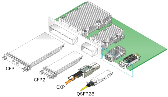
CFP Series (CFP/CFP2/CFP4) Transceivers
CFP series transceivers are the form factor pluggable optical transceiver. The volume of them is very large. From CFP to CFP4, their size becomes smaller and smaller. The size of CFP4 transceiver is only one-quarter of CFP transceiver. Nowadays, CFP4 transceiver’s bandwidth and power consumption have been greatly improved, making it more suitable for high-density 100G Ethernet.

CXP Transceiver
CXP fiber transceiver is 12 full-duplex channel modules with 12 x 10G transceivers. It has a smaller size than CFP transceiver and supports hot pluggable feature. And it mainly supports 100GBASE-SR10 of the short-distance transmission.
QSFP28 (Quad Small Form-factor Pluggable) Transceiver
The 100G QSFP28 is implemented with 4 x 25 Gbps channels and can achieve the highest possible rate of 4 x 28 Gbps. Its size is smaller than the CFP4 optical transceiver and you can switch with high port density. As the cost of the QSFP28 optical transceiver decreases, the QSFP28 optical transceiver becomes more and more popular.
Conclusion
As we can see, there are a variety of 10G and 100G fiber optic transceivers, and they are always boosting greatly. Both of them have their advantages and unique characteristics. You need to make choices based on your actual needs.
0 notes
Text
Fiber Optic Cable vs. Copper Cable: Which to Choose?
With the development of Internet, cable is becoming an important part of the Ethernet-based networks. As common cable wires, both fiber optic cable and copper cable can provide industries and homes with Internet. These two different types actually have several different varieties of uses either in office or residential areas. It may be difficult on how to choose them. But comparing them from five significant aspects may help you have a better choice.
Definition of Fiber Optic Cable and Copper Cable
Fiber Optic Cable
Fiber optic cable is a cable for transmission consisting of two or more glass or plastic fiber cores that are placed in a protective cladding and covered by a plastic outer jacket. It is used instead of metal wires because the signal traveling along it loses less. It is designed for long distance and high performance transmission in data networking and telecommunications. Hence, it is widely used for commercial business, governments, military and many other industries for voice, video and data transmission.
Copper cable
Copper cable is an old, cheap, and the most common form of transmission medium till date. It has been used in communication industry for many years and it is remained in use in many networks today. As an Ethernet cable, copper cable connects devices within the LAN, such as PC, routers, and switches. Copper cable has good performances and electrical interference protection, making it suitable for commercial networks, wiring inside office walls, and home networking setups.
Fiber Optic Cable vs. Copper Cable
The following part will compare fiber optic cable and copper cable from five aspects: bandwidth, transmission speed, security, reliability, and cost.
Bandwidth
Copper cable transmits data through electrical impulses, which is adequate for voice signals. But it has limited bandwidth and can support up to 10 Gbps with maximum 100m distance currently. However, fiber patch cable provides over 1000 times as much bandwidth as copper cable. For example, typical multimode fiber’s bandwidth can reach up to 4700 MHz/km, which means it can transmit 10 GHz over 550-meter cable.
Transmission speed
Because of the low attenuation and excellent signal integrity, fiber optic cable has longer cable segments than copper cable. Such as OM3 fiber, it can support Gigabit to 1 km, and for single mode cable, it even can reach up to 100 km. However, copper cable is limited to 100 m.
Security
Because copper cables operate through electrical signals, they can be easy to the effects of electromagnetic interference from lightning, nearby power lines or respiratory failure index (RFI) radio signals. However, fiber is an insulator, which means that no electrical current flows through it. So it is resistant to fire and electromagnetic interference. In short, data transmission through the fiber is slightly more reliable.
Reliability
Fiber optic cable is exactly stable that it is immune to the external environment like temperature changes, terrible weather, and moisture. But for copper cable, it is easy to be influenced by the factors of external factors. For example, if not properly installed, copper cables will produce electromagnetic currents that can interfere with other wires and decrease the network performance. Moreover, fiber optic cable does not cause a fire while a worn and old copper cable can.
Cost
Are copper cables cheaper than fiber patch cables? There is no clear answer yet, because there are many factors to consider. As a general rule, fiber patch cable is 1-5% more in cost than copper cable. From a long-term perspective, copper cable exactly costs less at the beginning, but it will be more expensive over the lifetime of the installation, maintenance costs, and downtime. As for fiber patch cable, because of its durability and reliability, the total cost of ownership will be lower.

Conclusion
We can see fiber patch cable and copper cable everywhere in our lives, both of them have their advantages and unique characteristics. Generally speaking, fiber patch cable is more suitable for large applications requiring higher bandwidth or spanning larger distance, and copper cable is more suitable for small applications like small office networks and family networks. But which to choose, depends on your actual demands.
0 notes
Text
How to Choose Multimode Fiber Optic Cable
Fiber optic cable can be divided into two types, single mode fiber and multimode fiber. As a common type of fiber optic cable, multimode fiber is typically used in short-distance buildings like campuses, industries, and local area networks. Do you really know it? We will have a detailed explanation in this article.
What is Multimode Fiber
Multimode fiber is a type of optical fiber that is mainly applied for short-distance transmissions. Compared with single mode optical fiber, multimode optical fiber has multiple modes of propagation. Its cores typically have a diameter of 50 µm or 62.5 µm, which gives them a higher "concentrating" capability and simplifies the connection. In recent years, Multimode fiber is considered as "domestic" fiber because it is mainly used in local area networks like FTTH and can reach up to 100Gbps Ethernet.
Common Types of Multimode Fibers
There are five common types of multimode optical fibers, namely M1, OM2, OM3, OM4, OM5. The following part will describe the characteristics and applications of each type.
OM1
The OM1 fiber usually has a core diameter of 62.5 micrometers and has an orange jacket. It can support 33 meters of 10 Gigabit Ethernet. It is most commonly used for 100Mbps Ethernet, short-range networks, local area networks, and private networks.
OM2
The OM2 fiber typically has an orange jacket like OM1 fiber. Unlike OM1, the core diameter of OM2 fiber is smaller, it is only 50 micrometers. OM2 can support up to 82 meters of 10 Gigabit Ethernet, but is more commonly used for 1 Gigabit Ethernet applications.
OM3
The OM3 fiber has an aqua color jacket. Like OM2 fiber, the size of the core diameter of OM3 is 50 micrometers. It can increase the speed by using fewer light modes. OM3 fiber provides 10 Gigabit Ethernet at lengths up to 300 meters, which is its main use.
OM4
Like OM3 fiber, OM4 fiber has the same jacket of aqua and core diameter of 50 micrometers. But compared with OM3 fiber, the development of OM4 fiber is a meaningful evolution, which can support 10 Gbps at lengths up to 550 meters and it supports 100 Gigabit Ethernet at lengths up to 150 meters.
0M5
OM5 fiber specifies a wider range of wavelengths between 850 nm and 953 nm with a jacket of green. It has the same core size as OM2, OM3, and OM4. It was created to support short wavelength division multiplexing (SWDM), which is one of the new technologies being developed for transmitting 40 Gbps and 100 Gbps. Now, OM5 becomes a potential new option for data centers that require greater link distances and higher speeds.
Multimode Fiber Choosing: OM1 vs. OM2 vs. OM3 vs. OM4 vs. OM5
Different multimode fibers have different diameters, jacket colors, optical sources, bandwidths, transmission distances, and more. We will have a table in the following part to help you choose the most suitable multimode fiber for your applications.


Conclusion
In summary, because of the high capacity and reliability, multimode fiber is commonly used in trunk applications in buildings of shorter distances, such as data center connections. Hence, multimode fiber optic cable remains the most cost-effective option for enterprise and data center applications in the 500-600 meter range. As for which multimode fiber should be chosen, you should consider the required application, distance, overall budget, etc.
1 note
·
View note