
Last Seen Blogs


fervour
𝒉𝒆𝒂𝒓𝒕 𝒐𝒇 𝒈𝒍𝒂𝒔𝒔.

poweredfluffyboys
My Heart Is Blue

joyshannonandthebeautymarks
Joy Shannon and the Beauty Marks

veryhuasuan
无标题
Text
How to use JLR CCF Tools and VBF Editor
Introduction to JLR CCF Tools and VBF Editor
JLR CCF (Control Configuration Files) tools and VBF (Vehicle Bus File) editor are software applications specifically designed for Jaguar Land Rover dealerships to configure and program vehicle control modules. These tools are only meant to be used by trained and certified technicians who have a working knowledge of vehicle systems and their components.
JLR SDD (Jaguar Land Rover Standard Diagnostic Device) Pathfinder is a software application used by Jaguar Land Rover dealerships for diagnosing and repairing vehicle systems. It allows technicians to access vehicle diagnostic information and perform various functions, such as reading and clearing fault codes, programming modules, and checking system status.
How to Use VBF Editor CCF Tools and VBF Editor
Here is a step-by-step guide to using the JLR CCF tools and VBF editor:
Step 1: Connect Diagnostic Device to Vehicle
Connect the JLR Standard Diagnostic Device to the vehicle’s OBD-II (On-Board Diagnostic) port.
Step 2: Launch JLR SDD Pathfinder
Launch the JLR SDD Pathfinder software and select the appropriate module that needs to
Step 3: Load CCF or VBF File
Load the relevant CCF or VBF file into the tool.
Step 4: Make Changes to Configuration or Programming
Using the CCF or VBF editor, make the necessary changes to the configuration or programming.
Step 5: Save Updated File to Diagnostic Device
Save the updated file to the diagnostic device.
Step 6: Upload File to Vehicle Control Module
Upload the updated file to the vehicle control module using the diagnostic device.
Step 7: Verify Changes
Verify that the changes have taken effect by performing a system test or checking for fault codes.
Conclusion
The CCF tools and VBF editor are powerful tools for configuring and programming vehicle control modules, but their use requires specialized training and certification. By following the steps outlined above, trained and certified technicians can effectively use these tools to diagnose and repair vehicle systems.
https://www.obd2tool.com/category-209-b0-JLR+VCI.html
0 notes
Text
How to solve when the new holland appear the EST release version has expired
Now the NEW Holland latest software version is CNH9.7, The brand new version of New Holland CNH EST works with OS Windows 10 64-bit and Windows 11 64-bit PRO, except the Home edition)
If you buy the new holland diagnostic tool with laptop, we have installed and activated software well before. You can use it directly afer receive. If you just buy the new holland diagnostic tool hardware with software, when you receive the goods,pls contact with us,we will activate it by remote for you soon.
Recently so many customer bought the NEW Holland diagnostic tool, then appear the error could not work as attached picture. how to solve it as below:
If appear this situation like above picture, because you change the computer time. So no matter the new holland diagnostic tool is with laptop or not. After we activated the software well.pls won’t change the computer time.or could not use any more.
How to solve this problem, you need contact with us to activate the software again, then you can use it.

0 notes
Link

supports Volvo FH series & FM series vehicles.
SUPPORTS Volvo Trucks / Volvo busses/ Volvo construction Equipment like Wheel Loader/ Aryiculated Hauler / Excavator/ Grader / Skid steer Loader / Compact Excavator /Paver / Others
0 notes
Text
Configure SDconnect to Xentry by cable
ou can operate XENTRY Diagnostics Open Shell using the SDconnect, too. To configure this hardware,please proceed as follows:
Start ConfigAssist by clicking on the button with the same name on your desktop (if you have restarted your system, the hardware selection window will appear first).
Select “SDconnect” if you are asked for the used hardware:
A conventional crossover Ethernet cable is required for connection of the SDconnect with the system via LAN. A suitable cable (green) is provided in the scope of delivery.
There are two possibilities for connecting the SDconnect and the system via the Ethernet cable:
– direct connection between two Ethernet connections (see section 3.2.2)
– connection with the help of a USB2LAN adapter to the system or via a USB2LAN cable
The LAN connection of the SDconnect is located on the right side under a protective cap.
Note:
Please ensure that the SDconnect is restarted before configuration and not in sleep mode. It is best to fully charge the SDconnect beforehand
Configuring a direct Ethernet connection
For the configuration of the LAN connection use the following values (static TCP/IP):
IP address on the PC (LAN connection on the PC to the SDconnect): 172.29.127.X (“X” stands for a number between 1 and 254).
Please note that the number automatically given for the SDconnect 172.29.127.129 cannot be used for the PC.
The PC subnet mask (LAN connection on the PC to the SDconnect) has the IP address 255.255.0.0 and should not be modified.
Important: Please configure your firewall to permit the communication of your system with the SDconnect (you will normally be prompted to do so the first time you connect the SDconnect via a cable connection). Please note that in the case of a direct Ethernet connection the LAN port can no longer be used for another connection!
When using DoIP, please also observe the additional firewall settings for the DoIP connection.
Configuring a USB2LAN connection
For a cable connection via the USB2LAN adapter, this adapter must be configured in Windows.
We differentiate between
– The installation or modification of the drivers for the USB2LAN adapter
– The configuration of the network connection via the USB2LAN adapter
The driver for the adapter must be installed using Windows dialogs. Any changes to the driver also need to be carried out using Windows processes and dialogs.
For the initial configuration of the adapter or when modifying the driver setup, basic knowledge of how to work with Windows components and drivers is required. Please consult your local
IT administrator in case of any uncertainty! The support centers for the XENTRY Diagnostics Open Shell systems cannot provide support for the configuration of drivers or Windows!
Installation of the USB2LAN adapter driver
To install the driver for the USB2LAN adapter, start by connecting the adapter to the computer without connecting the green cable to the SDconnect at the other end. Make sure that the computer is online,i.e. that the Internet connection is working properly.
Automatic driver installation – first-time installation
If you want to connect the adapter to the computer for the first time, start the automatic Windows driver installation (Windows 7 and later versions). The driver only needs to be installed once the first time that you connect the adapter. Please proceed with caution since communication is not possible if the configuration of the USB2LAN adapter between the computer and SDconnect is absent or incorrect. The drivers for the adapter may need to be uninstalled and reinstalled or reconfigured manually.
Important: It may not be immediately clear whether Windows is attempting to install the driver for the first time or whether the system immediately uses the driver after (repeatedly) reinserting the adapter, since Windows hides these status messages in the Windows tray in the default setting.
With the first connection attempt, Windows will attempt to identify the driver software and download it from a website containing drivers online. Windows will display a notification for a number of seconds in the Windows tray during these actions:
If you do not promptly click the dialog balloon, Windows will hide the symbol in the windows tray behind the small arrow symbol:
After clicking the symbol, Windows will show additional information:
It is important to install the driver for the device “USB-MAC Controller”.
Please wait until Windows has identified and downloaded the required drivers online.
This can take some time – do not terminate the process!
At the end of the process Windows will notify you of the results of the driver installation:
– Installation successful, device is ready for use
– Installation unsuccessful
After a successful installation, you can start to configure the adapter immediately
Automatic driver installation – later installation
If you accidentally terminated installation the first time you plugged in the adapter or if the installation failed (e.g. because the computer was offline), you need to install the drivers again. This may also be necessary after you have connected the adapter to a different USB port than the port first used.
To install the driver at a later stage, you will need to click on “Devices and Printers” in the Windows Control Panel, then “Other Devices” (or potentially “Network Adapters”) and “USB-MAC Controller”. The entry “USB-MAC Controller” will very likely be shown with a yellow exclamation point, since there is a driver problem.
If the USB2LAN adapter has been partially installed (incorrectly), it can be found in the Device Manager under “Network Adapter” and otherwise under “Other Devices”.
Important: The “USB-MAC Controller” only appears under “Other Devices” or “Network Adapter” when it is plugged in!
Right-click on the entry “USB-MAC Controller”. The context menu will open. Here, select “Update driver software”:
When you select “Update driver software” in the context menu, if the computer is online you
can choose “Search automatically for updated driver software”. Otherwise, please select “Browse my computer for driver software”:
Selecting “Search automatically for updated driver software” will run the automatic installation process as described above.
Manual driver installation – later installation
If the initial automatic driver installation failed or the later automatic installation was also unsuccessful or if the system is generally not online, the drivers for the USB2LAN adapter
must be installed manually.
Note: The driver software for the USB2LAN adapter is supplied on every update DVD/BD.
Start by determining whether you have a 32-bit or 64-bit version of Windows 8.1 or Windows 10. Go to the “Control Panel” and “System” in the Windows Start Menu. There you will find information on the system type:
As described above for the “Automatic driver installation – later installation”, open the menu item “Update driver software” for the USB2LAN adapter in the Windows Device Manager.
In the dialog, select “Browse my computer for driver software”, insert the installation DVD/BD and browse the disc manually to locate the following folder:
– “USB2LAN Driver\Windows 7\64 bit” (for Windows 7 64-bit) or
– “USB2LAN Driver\Windows 7\32 bit” (for Windows 7 32-bit).
Please select your specific Windows version if not “Windows 7” when applicable.
Windows then installs the driver offline from the selected folder.
Normally you only need to select the folder and Windows will automatically find the required driver files. If this should fail, please select the corresponding *.inf file in the folder (“netmosu.inf” for 32-bit, “USBMAC64.inf” for 64-bit).
Configuration of the USB2LAN adapter and SDconnect for cable operation
Before configuring the USB2LAN adapter, the driver installation must be completed successfully. Make sure that the adapter is connected and that no error is indicated in the Windows tray (yellow exclamation point, installation of device drivers, etc.)
Please note:
Always plug the USB2LAN adapter into the USB port used to install the driver.
The USB2LAN adapter may not be recognized by a different slot.
Switch on the SDconnect and wait until it has started up. Ensure that the SDconnect is connected to an external power supply or to the vehicle via the OBD cable to receive power.
The SDconnect must not go to sleep during configuration!
The configuration consists of three main steps:
– Establishing the connection
– Assigning a manual IP address to the USB2LAN adapter
– Configuring the connection via SDconnect Administration.
Establishing the connection
Connect the green Ethernet cable to the SDconnect and then to the USB2LAN adapter.
Windows will now attempt to establish a network connection between the computer and SDconnect via the adapter and the cable. This may take a few moments.
The connection status is not immediately visible. To check the status, you may go to the Windows Control Panel > Network and Internet > Network Connections. With a successful connection,the LAN connection of the “High Speed USB-Ethernet Adapter” will be fully functional (i.e. no red “X”; no yellow exclamation point). If you use the context menu to call up the “Status” for this adapter and “No Network Connection” is shown, an IP address should still be entered under “Details…” and “Auto configuration …“
Assigning a manual IP address
Call up the connection properties of the using the USB2LAN adapter from the Windows Control Panel >Network and Internet > Network Connections (Adapter “HighSpeed USB-Ethernet Adapter”) by doubleclicking or using the context menu (“Properties”).
Select the “Internet protocol Version 4 (TCP/IPv4)” and click “Properties”. Select “Use the following IP address:” and enter this information:
IP address: 172.29.127.X
Subnet mask: 255.255.0.0
Please note that “X” stands for a number between 1 and 254. The default address automatically assigned to the SDconnect 172.29.127.129 cannot be used for the adapter!
Leave all other entries in the window the same and close the dialogs with “OK”.
If Windows determines that the assigned static IP address is already in use, please choose a different IP address, i.e. a different number for the “X” above.
Connection configuration
If the connection with the manual IP address has been established, you still need to assign a specific number to the SDconnect.
Call up the SDconnect Administration (Start > All Programs > Mercedes-Benz). Click on the SDconnect entry with an unknown or not yet assigned number and wait for the SDconnect data to be loaded. Under “Select name” choose any number that is NOT assigned to a different SDconnect in your workshop. Use the number clips included with delivery to label the device.
Save your entry by clicking “Start” and exit the SDconnect Administration after confirming that the program has applied the data.
After successful configuration of the cable connection to the SDconnect:
Numerous icons in the Windows tray show the status of the SDconnect (system restart may be required).If an SDconnect is connected, the icons display the number of the SDconnect (here: 10), the connection type (Wi-Fi) as well as a padlock icon:
You may have to adjust the settings of the Windows tray in order to see these icons.
https://www.obd2tool.com/blog/how-to-configure-sdconnect-to-xentry-by-cable/
0 notes
Text
John Deere Service Advisor Software v5.3 AG/CF
John Deere Service Advisor EDL (Electronic Data Link) heavy duty diagnostic adapter for construction equipment, agriculture, engines John Deere.

John Deere Service Advisor is the Diagnostic Kit that allows users to perform diagnostic for service of agricultural, construction, and forestry equipment. With Service Advisor you can view service manuals, use DTAC (Technical Assistance Center) data, make diagnostics, readings, tests, calibrations, and re-program controllers.
John Deere Service Advisor v5.3 is the version that completely replaced SA v4.2 starting in the 2017 year, an entirely new interface design with more system requirements for better performance. It is fully compatible with Windows 10 including EDL v2 & v3 KIT. No longer needs DATA DVDs with model data or Historical information. All the files are available on a USB Stick or HDD and can be easily accessed via SA web search. So, you no longer need to play with dozen DVDs to be able to get a proper manual or DTAC solution.
Languages: English, French, German, Italian, Portuguese, Russian, Spanish.
Data update: 08.2020 (Agricultural & Turf + Construction & Forestry machinery).
Version: v5.3
John Deere Service Advisor 5.3 System requirements:
* O.S.: Windows 7 SP1 or higher
* CPU: 1.60 GHz or higher
* RAM: 2 GB of system memory or higher recommended
* Hard Drive: 350 GB of available space
Installation: The program will be fully installed and activated remotely via TeamViewer or AnyDesk session. After successful payment, you’ll receive an email instantly with the download link and further instructions. If you don’t receive the email after payment, make sure to check your spam folder or contact us via the live chat from the icon at the bottom right corner. All our packages are stored in a MEGA premium account for a better download experience. A failed installation will result in a full refund.
0 notes
Text
New Holland Electronic Service Tools CNH EST 9.7 Upgrade
New Holland Electronic Service Tools (CNH EST v9.7) (v9.4, 9.5, 9.6) Engineering Diagnostic Software
Electronic Service Tool 9.7 (EST) Engineering Level* (software only) – used by New Holland dealer technicians to connect with vehicles that have a Controller Area Network (CAN) BUS.
The brand new version of New Holland CNH EST works with OS Windows 10 64-bit and Windows 11 64-bit PRO, except the Home edition).
Important notice! Please make sure you have checked the minimum system requirements. If your laptop is unsuitable for CNH EST v9.7, we can install v9.4 instead. Which has lower hardware requirements.
*for advanced dataset registration, a lot of hidden options programming for vehicles, and raw message simulations.
Electronic Service Tool Software Brands coverage:
– Case IH Agriculture
– Case Construction
– New Holland Agriculture
– New Holland Construction
– STEYR
– Flexi Coil
– Miller
– Kobelco
Optionally, you can purchase eTimGo for CNH EST 10.2022 for all brands OFFLINE which is a completely offline repair and diagnostics information database. With PIN search support.
NOTE: EST 9.3.0.0 will timeout on July 31st, 2021. All support for Windows 7 and 8.x will be closed.
EST 9.7.0.0 New Features
The release of the Electronic Service Tool (EST) 9.7.0.0 and new eTIM software includes several improvements to the service tool software. These changes include:
– EST PC Operating System (OS) and hardware requirements
– Windows 11 support
– EST Software Installation and licensing
– DPA5 Hardware and Firmware updates
– EASy ECU programming crashing
– New Models in EST9700
The software EST v9.7 comes as:
CNH EST 9.7.0.0.0 installation file,
CNH EST 9.7.0.0.2 (EST9700Up1) update,
Controller Package v85 (11/2022),
EASY Software installation package,
New Legacy Diagnostics database for Troubleshooting,
PC locked activation
Teamviewer remote assistance with setup & activation
The software EST v9.6 comes as:
CNH EST 9.6.0.0.0 installation file,
CNH EST 9.6.0.0.2 (EST9400Up1) update,
CNH EST 9.6.0.0.3 (EST9400Up2) update,
CNH EST 9.6.0.0.4 (EST9400Up3) update,
CNH EST 9.6.0.0.5 (EST9400Up4) update,
CNH EST 9.6.0.0.6 (EST9400Up5) update,
CNH EST 9.6.0.0.7 (EST9400Up6) update,
CNH EST 9.6.0.0.8 (EST9400Up7) update,
CNH EST 9.6.0.0.9 (EST9400Up8) update,
CNH EST 9.6.0.0.10 (EST9400Up9) update,
CNH EST 9.6.0.0.11 (EST9400Up10) update,
CNH EST 9.6.0.0.12 (EST9400Up11) update,
Controller Package v78 (08/2022),
EASY Software installation package,
New Legacy Diagnostics database for Troubleshooting,
PC locked activation
Teamviewer remote assistance with setup & activation
What’s new with EST 9.6.0.0
EST 9.6.0.0 New Features
The release of the Electronic Service Tool (EST) 9.6.0.0 includes several improvements to the service tool software. These changes include:
– EST PC Operating System (OS) and hardware requirements
Minimum Specifications:
Processor:
Intel Core i5 6th Gen Processor or higher (Manufactured in 2015 or later)
RAM Memory:
8 GB or greater
Operating System:
Windows OS: Windows 10 64-bit Note: A 64-bit operating system is mandatory
Hard Drive:
250 GB or greater – Solid State Drive (SSD) is recommended for improved performance
Ports required for adapter connection:
One 9 pin Serial port (preferred) OR USB to RS-232 Converter – (FTDI Chipset) 380003514 – USB to RS232 adapter
– New diagnostic adapter support
The EST9600 base software introduces support for a new diagnostic adapter to interface with CNHi equipment.
EST9600 will support both the DPA5 and CoreXS and allows for easy conversion between these two diagnostic adapters.
To view the connector selection with EST9600, click Communications in the top ribbon.
In the dropdown menu, hover over the Communications Adapter Selection.
– Legacy Diagnostics download and installation
The new legacy troubleshooting database is released and will be available with the EST9600 software.
What’s new with EST 9.5.0.0
The release of the Electronic Service Tool (EST) 9.5.0.0 and new eTIM software includes several improvements to increase the ability of the user to service and diagnose equipment. These changes include:
– EST PC OS and hardware requirements
– EST Software Installation
– Equipment Auto-Detection Support
– EASy Software Management
– EASy Injector Cutout Test Improvements
The software EST v9.5 comes as:
CNH EST 9.5.0.0.0 installation file,
CNH EST 9.5.0.0.2 (EST9400Up1) update,
CNH EST 9.5.0.0.3 (EST9400Up2) update,
CNH EST 9.5.0.0.4 (EST9400Up3) update,
CNH EST 9.5.0.0.5 (EST9400Up4) update,
CNH EST 9.5.0.0.6 (EST9400Up5) update,
CNH EST 9.5.0.0.7 (EST9400Up6) update,
CNHSupportUpdate_27790_3_2_10,
EasyNETMainProgram_27787_10_18_1,
ECM_MD1CS069_DA_FPT_27696_0_45_7,
EDC16C39_P_CNH_1_3_SETUP_28684_1_10_1,
EDC17CV41_CAN_D_CNH_Setup_29247_0_16_1,
EDC17CV41_DA_CNH_28427_1_4_6,
EDC17CV41_VECTOR_DatiMemorizzatiMuda_IV_setup_23505_1_19_6,
MD1_ET_28410_0_3_1,
MD1CS069_DatiMemorizzati_setup_27994_1_2_4,
MD1CS069_DB_27950_0_2_1,
MD1CS069_DB_28493_0_4_7,
16.1.1.0
EST Legacy Diagnostics package,
Vehicle Controller Files v67 (03/2022 date of update)
PC locked activation
Teamviewer remote assistance with setup & activation
The software EST v9.4 comes as:
CNH EST 9.4.0.0.0 installation file,
CNH EST 9.4.0.0.2 (EST9400Up1) update,
CNH EST 9.4.0.0.3 (EST9400Up2) update,
CNH EST 9.4.0.0.4 (EST9400Up3) update,
CNH EST 9.4.0.0.5 (EST9400Up4) update,
Vehicle Controller Files v46,
Legacy Multilanguage Diagnostic Procedures installer,
Optionally, by request, with Additional assistant Programs,
PC Locked Activation tool with the engineering access level.
The software EST v9.3 comes as:
CNH EST 9.3.0.0.0 installation file,
CNH EST 9.3.0.0.2 – 9.3.0.0.7 (EST9300Up5) updates,
Legacy Multilanguage Diagnostic Procedures installer,
Optionally, by request, with Additional assistant Programs,
PC Locked Activation tool with the engineering access level.
What’s new in the CNH EST v9.2 upd. 1 – 10
EST_9200_Update_1_Details
EST_9200_Update_2_Details
EST_9200_Update_3_Details
EST_9200_Update_4_Details
EST_9200_Update_5_Details
EST_9200_Update_6_Details
EST_9200_Update_7_Details
EST_9200_Update_8_Details
EST_9200_Update_10_Details
IMPORTANT NOTICE. Service Manuals, Schemes available only online.
In case if your PC/Laptop doesn’t fit with the minimum hardware requirements, we can offer the CNH EST v9.0 (2019/01), which is still compatible with the 32-bit windows and 3/4 Gb of RAM. Please indicate the desired application version in the comments field. Or via the contact us form.
New minimum PC specifications
All computers must use a 64-bit version of their operating system. The older 32bit options are limited to 4 gigabytes of RAM, and cannot provide enough performance to run these programs.
Minimum Specifications
Processor: Intel Core i5 Processor or higher(manufactured in last 3 years);
RAM Memory: 8 GB or greater;
Operating System: Windows OS: 64-bit (Mandatory)
Windows 10 PRO (Recommended)
Hard Drive: 250 GB or greater;
Ports: One 9 pin Serial port (preferred) OR USB to RS-232
Converter – FTDI Chipset)
Two USB ports
10/100 Ethernet
WiFi 802.11b / g
Bluetooth
Mobile Wireless (recommended)
The following brands of the CNH group are covered:
New Holland (Agriculture and Construction)
New Holland FK (Fiat-Kobelco)
New Holland O&K (Orenstein & Koppel)
CASE (Agriculture and Construction)
STEYR
KOBELCO
Iveco (Astra) (articulated dump trucks only)
Flexi-Coil
Sumitomo (S.H.I.)
Link-Belt
The last version of CNH EST with technical documents is 7.6. If you need electrical schemes, please consider purchasing CNH EST 7.6 version on virtual PC with Windows XP Works with any Windows platform.
New Holland Electronic Service Tool allows you to:
• Check the status of parameters;
• Retrieve faults;
• Run diagnostic tests;
• Make ECU and parameter programming;
• Monitor active and logged diagnostics;
• View and change ECU configuration;
• View diagnostic procedures and schematics.
• Troubleshoot problems;
• Run scope diagnostics;
CNH EST can be downloaded, or we can send it as a set of DVDs
We recommend using our free remote assistance with the setup and activation process.
If you have advanced Computer Skills, we can provide you with all the information for installation and activation
https://www.obd2tool.com/blog/new-holland-electronic-service-tools-cnh-est-software-upgrade/
0 notes
Text
AUTEL IM508 WITH XP400 PRO PROGRAM BENZ W207 KEY
In the previous article, you can learn the guide to successfully read Benz EIS W207 data via OBD using Autel MaxiIM IM508 with XP400 Pro. Today you can see how to calculate the password and program key with the EIS data readout.
Firstly, prepare all devices incl. one original key and one blank key, etc.
Make sure the connections of all devices are correct.
Then operate on Autel IM508 key programmer.
Read EIS data before adding key, please refer to this post:
Read Benz W207 EIS Data by Autel IM508 with XP400 Pro(5-5.txt)
Start to add key in 6 steps
Go to the “Control unit” menu, tap “Add key”-> “On bench”-> “W207”
There is an EIS wiring diagram, we have already connected it, so just click “OK”
(If you don’t know how to connect, just refer to it)
Click “Begin” to start adding key
Step 1: Read EIS data successfully
Step 2: Read ignition key information
Put the original key close to the XP400 Pro programmer and press any button
Then insert the key into the coil of XP400 Pro
This is not a smart key, click “No” to continue
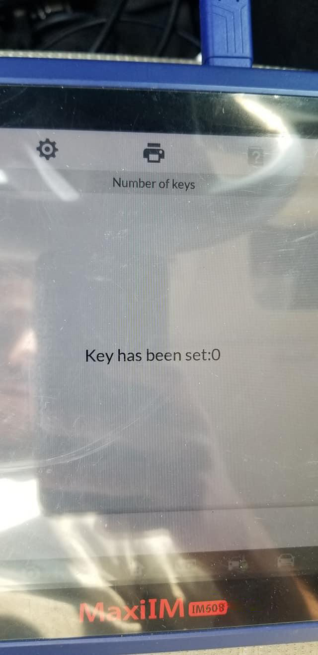
Read out the number of possible existing keys
Step 3: Read blank key information
Put the blank key close to the XP400 Pro programmer and press any button
And then insert the key into the IR keyhole on the programmer
Step 4: Obtain key password
There is not a key password, just click “No” and press “OK” to enter the password calculation process
When the password calculation is done, insert the original key into the EIS and wait for 5s. After that, pull the ignition key out
Insert the original key into the EIS lock again and wait for 2s
Then confirm whether the key can be turned to the ON position
Note: If it cannot do on the bench, please remove the key and try again until it can be turned to the ON position.
If operating in a car, please pay attention to whether the instrument panel is illuminated when the key is turned to the ON position. Try again if the key cannot be turned to the ON position.
Pull the original key out and insert it into the IR keyhole on the XP400 Pro programmer again
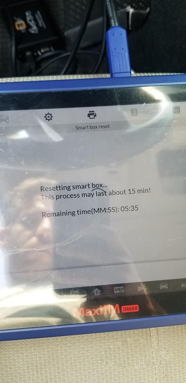
It will take about 10-30 min to calculate the password, please keep patient.
Password calculation is successful.
Insert the original key into the EIS and wait for the 30s
Password calculation completed
Step 5: Generate the key file
Insert the blank key into the coil of XP400 Pro
Add key successfully
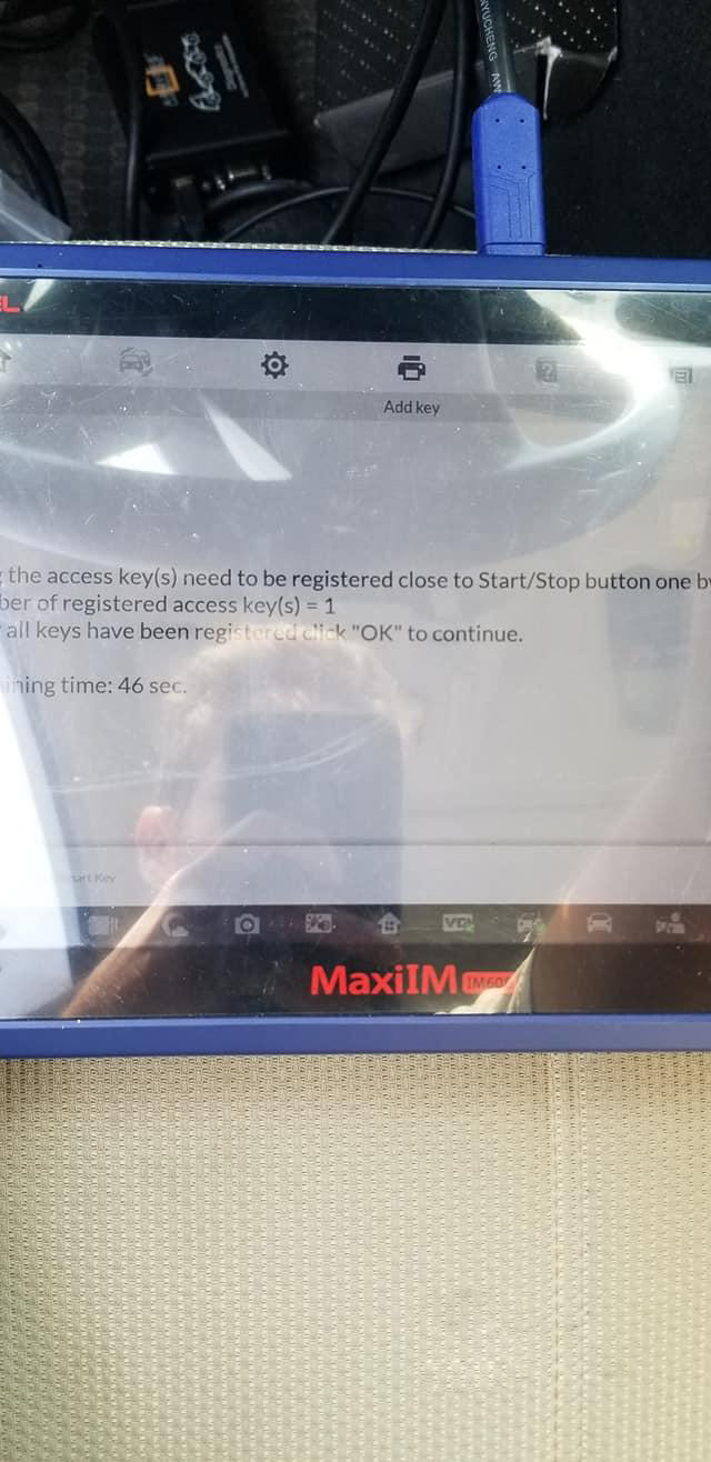
Step 6: Test the new key
Finally, follow the on-screen instruction to test the new key
Insert the new key into the EIS to learn, it works and means the new key has been programmed successfully
That’s all!
0 notes
Text
How to Read Benz W207 EIS Data by Autel IM508 with XP400 Pro
Autel MaxiIM IM508 with XP400 Pro supports the same advanced functions as Autel IM608 and IM608 Pro incl. Mercedes infrared key read/write, remote frequency detection, Benz 3rd generation IMMO add key, all keys lost via OBD, 2015-2019 Jaguar Land Rover write key via dump and Volvo Smart key/Fobik smart key learning. This post will share the guide to use to read Benz EIS W207 data via OBD.
All devices required:
Autel MaxiIM IM508 with XP400 Pro Key and Chip Programmer
Mercedes- Benz EIS/ELV
Instrument
Gateway
Note: All Benz control modules above have been disassembled from the car.
Connection:
Connect MaxiIM IM508 to the dashboard via OBDII main cable
Connect XP400 Pro with IM508 via the programmer USB cable (Its color is black)
Note: Don’t connect XP400 Pro programmer to the vehicle OBD connector via OBDII cable.
Operation:
Enter “IMMO” function of the IM508 tablet-> Select “Mercedes Benz”
Make sure the xp400 pro has been connected to IM508 properly
Select “Automatic selection”-> tap “Read” to read out VIN automatically (No need to enter VIN manually)
Read out the vehicle info and confirm if it is correct
Select “2008-2014”-> “Control unit”-> “EIS tools”-> “Read EIS data”-> “OBD”-> “On vehicle”-> “Auto scan”
Identify the EIS type is W207
Read out the EIS info and the car key No.1 and No.2 position have been used
Save the EIS data, then you can upload the data to the server to calculate the password and program key.
Done!
0 notes
Text
JLR Mongoose SDD V160 Software Win7 Win10 Free Download
How to do if the JLR Mongoose SDD installation package was damaged or could not be opened? Here we have provided SDD V160 software free download that works for Windows7/ Windows10.
Where to free download JLR SDD V160:
Step 1: free download SDD V160:
http://diagnosticdelivery.jlrext.com/idscentral
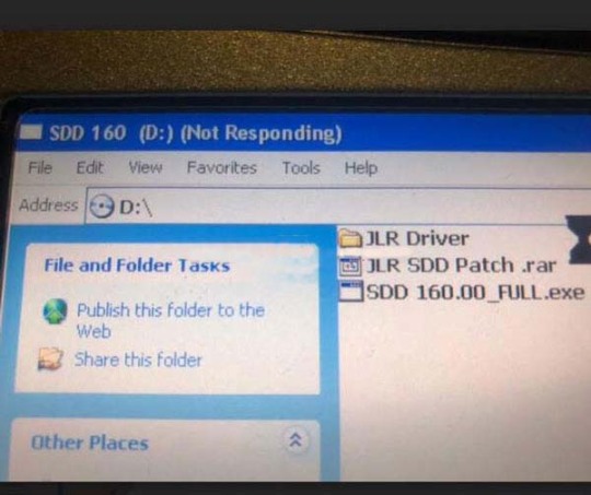
SDD 160.00_FULL.exe: It applies to the user who requires when the SDD machine does not have the previous SDD software installed.
SDD 160_159 UPDATE.exe : It applies to the user who requires to update an SDD machine from the previous SDD software to the latest SDD Software.
SDD 160.01.exe: Contains SDD application enhancements and vehicle software updates and is to be installed after the FULL SDD Software
Step 2: free download SDD V160 driver:
http://drewtech.com/downloads/index.html
—-> For VXDIAG NANO SDD driver, download here: www.vxdiag.net
Step 3: free download SDD V160 patch:
https://mega.nz/#F!zBpSFarJ!phCGoR3RGYqOHYQa9kVBIw
Compatible system: Win7, Win10
Note: V160 version does not support the XP system.
Compatible system: Win7, Win10
Note: V160 version does not support the XP system.

How to solve JLR Mongoose Pro installation error?
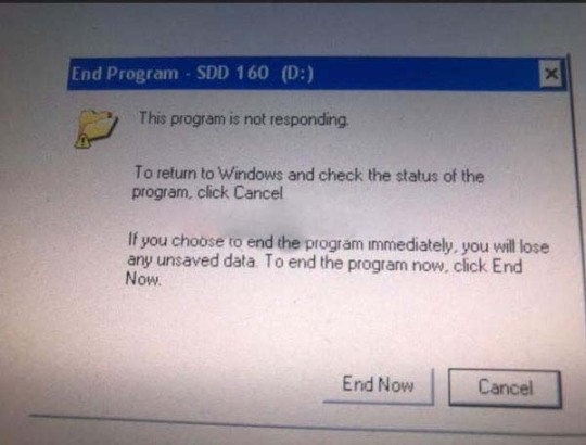
Error case 1:
End Program – SDD 160 (D:)
This program is not responding.
To return to Windows and check the status of the program, click Cancel.
If you choose to end the program immediately, you will lose any unsaved data. To end the program now, click End now.
Solution: the computer system is not compatible with SDD V160, please try other computers with Win7/ Win10.
Error case 2:
This installation package could not be opened. Contact the application vendor to verify that this is a valid Windows installer package.
Solution: SDD installation package was damaged. Please re-download it from our link. Tested and safe.

Hope it works.
0 notes
Text
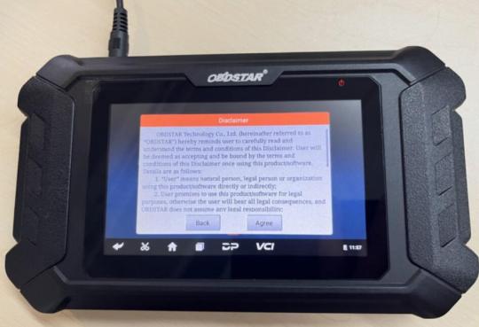
How to Solve OBDSTAR Failed to Connect WiFi or Hotspot Problem
Here is the working solution for OBDSTAR tools failed to connect iOS wifi or hotspot problem. Affected obdstar device: obdstar odomaster miles programmer with serial number 90140002 ****. x300 dp plus (Key Master dp plus), x300 pro4 (Key Master 5) firmware file will be released in January 2022.
The solution fixes the following WiFi or hotspot problems:
1. I’ve tried 3 different phone hotspots, nothing works. Only works on my home WiFi router. Ordered a mobile WiFi router and only works on it when switching to 3G, when switching to 4G no possibility of communication with Server
2. After buying obdstar, it will search for WIFI for 2s or 3s seconds and then stop
3. I dropped my obdstar from about 2 feet. Now I don’t have a screen.
4. I have obdstar dp300 Today there is a problem that I cannot connect to the hotspot from my phones. I can only successfully connect to WiFi networks at home or in the office.


OBDSTAR Firmware Upgrade Guide
Preparations:
The firmwate file to be upgdade (Update_XP50 for Odomaster)
The firmware file name format is update-dp[xx]_[yyyyy][mm][dd].img
Such as update_dp50_20211221.img means DP50 firmware released on December 21, 2021.
2.A TF card with a capacity greater than 1G and a TF card reader. All files inside the card will be cleared during the operation, backup first.
3. Download SD_Firmware_Tool_v1.57.zip
Backup DP Software
Warning: Upgrading the firmware will erase all the settings in the device and all the software in the DP. Users who have expired cannot download the software again through the one-click upgrade, so the software in the device needs to be backed up.
1. Insert a TF card with a capacity greater than 16G into the device to back up the DP software
2. Click the Main menu button on the main screen, select and enter ES File Manager

3. Locate and long press the DP folder, select DP folder and click on the Copy button


4. Click the Menu icon on the left, expand the local area, select Home page

5. Select external_sd (TF card), and then click the Paste button. Wait for the copy to complete. After the firmware upgrade is complete. Just overwrite the DP directory from the TF card to the device.
Making upgradeable TF card
1. After inserting the TF card into the card reader, insert the card reader into the USB port of the computer

2. Unzip the SD_Firmware_Tool_v1.57.zip and run SD_Firmware_Tool.exe
3. Follow the steps below
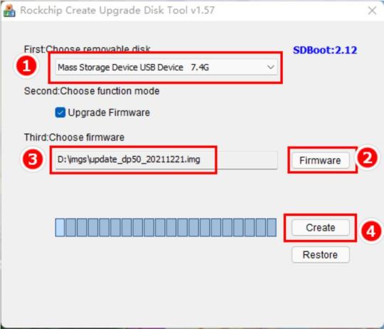
Operating instructions:
Make sure that your TF card information and capacity size can be seen, if not check that the TF card reader is properly inserted into the USB port.
Click the Firmware button to select the firmware file
Click the Create button to start writing the firmware file to the TF card

4. Wait for the prompt Creating upgrade disk ok. The upgradable TF card is made successfully.
Update Firmware
Warning: plug in the power adapter for the device and ensure that the power indicator is on. Do not power off during the upgrade process.
1. Insert the TF card into the device

2. Make sure the device is plugged in and the power light is on. Long press the device power button and select Reboot.

3. The device will automatically perform a firmware upgrade and a progress bar will appear.

4. When screen says ‘Doing Activation Succeeded, please remove the SDCard’, remove the TF card from the device, the device will automatically reboot and enter the system

5. Firmware upgrade is completed.
6. Check current firmware version.
Got o Settings- About- Build number is the current firmware version.

Reconnect WiFi or hotspot, it should be fine.
0 notes
Text
2013 YAMAHA TMAX 530 ENG DIAGNOSIS by MS80 motorcycle scanner
OBDSTAR MS80 has professional-level intelligent diagnosis, providing an unprecedented intelligent diagnosis and maintenance experience-the first fault guidance, technical bulletin, data flow assistance, diag socket, and other functions to help you diagnose accurately and efficiently; exclusive interactive circuit diagram and electrical query system, easy troubleshooting Failure, so you have no worries about the car diagnosis!
Obdstar MS80 Functions:
1. New Android 5.1.1 operation system
2. Simple and intuitive menu guidance allows you to quickly master the equipment operation;
3. Provide complete diagnostic functions including code reading, code clearing, data flow, action test, setting, coding, etc.;
4. Menu Arbitrary selection is more convenient and quick;
5. Record and play back real-time data streams, quickly and accurately locate sensor and component faults;
6. Wi-Fi connection to the Internet, one-click software upgrade;
7. One-Click remote function, OBDSTAR technical staff remote assistance;
8. Support the fault diagnosis of most of the world’s luxury locomotives and tens of thousands of models.
Obdstar MS80 Advantage function:
1. The first fault guidance, Help data, technical bulletin, diag socket, etc. help you diagnose accurately and efficiently;
2. Exclusive interactive circuit diagram and electrical description query function, so that you can have a worry-free diagnosis;
3. Diversified data stream display modes such as text, waveform diagram and instrument diagram, allowing you to easily analyze faults;
4. Automatic scanning, automatic VIN recognition, control module programming and coding, ECU setting, instrument coding, tire pressure monitoring system, maintenance light reset, CO adjustment, idle speed adjustment, A/F value reset, ABS control unit setting , EOL mode, transmission memory reset, clear computer memory, etc.
This article is intended to share with customers the tutorials on OBDSTAR MS80 Motorcycle Diagnostic Tool 2013 YAMAHA TMAX 530 ENG Diagnostic Test.
Operation Procedures:
Plug main cable to OBDSTAR MS80 diagnostic scanner>> Connect main cable with M040 adapter for BMW>> Connect the device to the motorcycle of “2013 YAMAHA TMAX 530.
Click the App “DiagProgram” on desktop>> “Moto Diag”>> “YAMAHA”>> “YAMAHA V30.32”
The screen appears message of “Initialization Communication”…
After it is done, click “Select from system”>> “Auto Scan”
Then, the MS80 diagnostic tool will begin its scanning process.
Prompted message: Turn off the ignition. Just follow what it says.
Click on “Enter” on the bottom right of the screen and it says “Turn on the ignition”.
Again, do it as required.
Click on “Enter” button and it will begin communicating.
It requires to “Turn off the ignition”again, repeat clicking the “Enter” button.
This part of the process is repeated several times. Remember: do whatever appears on the Tools screen until it gets into the “Auto Scan” interface.
Click the “Engine Control Unit”
Turn off the ignition-> Enter->Turn on the ignition->Enter, repeat this operation once again.
Under “Information” column, it lists what you can do as below:
Click “ECU Information, the tool starts reading ECU information and show the details as seen:
Back to the “Information” column and click “Read fault codes”, if there are no DTCs, it will prompt the message of “No fault codes”.
Click “Read data flow”, the Live data is shown below:
Click “Active Test”, you can see:
Click “Special Function”>> “Writing Frame Number”, you can check the exact current frame number of your motorcycle.
Test Completed!
That’s all. Thank you for sharing your time with us!
0 notes
Text
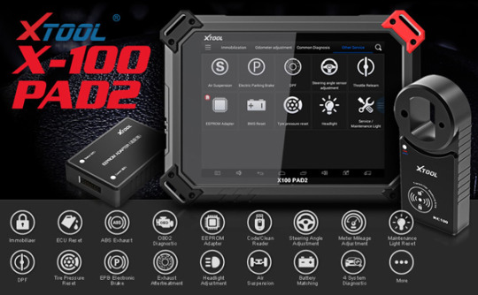
LICENSE EXCEPTION ERROR SOLUTION ON VW FOR XTOOL PAD2
XTOOL PAD2 with strong functions which can do key programming and special functions .
Problem : When use the machine work with my VW , there have an error : “ License exception ! “
Solutions :
1: Connect the X-100 Pad2 to PC and power
2: Activate X-100 Pad2
Press Login account and login with email address
Enter “Activation Code” which you can find on the user manual
Complete all information and click on the “ACTIVATE” button
Activation complete. Go to x100 pad2 main menu.
Then open resource Manager and delete the XTOOL file there.
3: Run an upgrade
X100 Pad 2 updated directly online using WiFi or USB connection.
To access the update application, open the XTOOL X-100 PAD 2 pro APP and click “UPDATE”

0 notes
Text
Xhorse Dolphin XP-005 “Error 56” “error code 6” Solutions
Question:
Xhorse Dolphin XP005 prompts “Error: 56” and “error code: 6”. Have shot and sent the video of electrical conductivity measurement, please check.

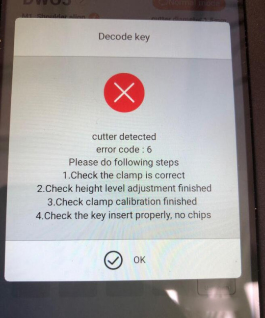
Solutions:
Check the steps as the prompts. (height level adjustment, clamp calibration etc.)
Do the electrical conductivity measurement.
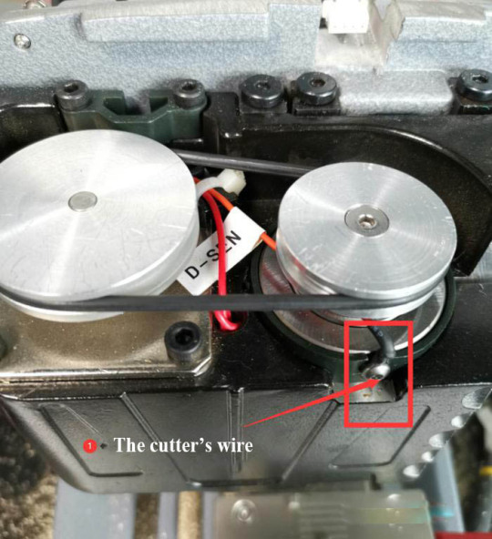
If the cutter and the probe don’t conduct, disassemble the machine and test abnormal conductivity of the cutter/probe.
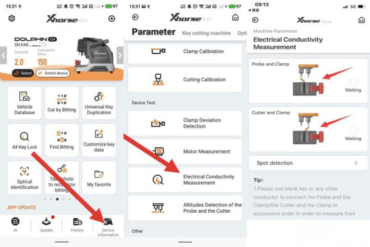
How to do electrical conductivity measurement?
Go to Xhorse app.
Device information>>Electrical Conductivity Measurement
1)Probe and clamp
2)Cutter and clamp
Use a blank key or a conductor to short-circuit the clamp and the probe/cutter as the prompt.
How to test abnormal conductivity of the cutter/probe?
Step 1
Unscrew the back of Dolphin XP-005, and watch the cables inside.
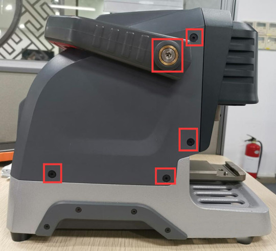
Step 2
Remove the back.
Unscrew the cable and the two Phillips screws.

Turn to the front side.
Unscrew the little rubber cover, and behind are screwed.
Then unscrew the long metal by a hexagon bar wrench.

Step 3
Use a slotted screwdriver to turn the screw so that the Z-bearing and the outer cover are in the same horizontal plane.

Take down the outer cover of the Z-bearing after the adjustment.
Unscrew the screws beside the probe.

Care the wire inside when removing the base.

Step 4
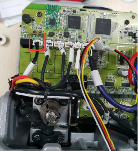
When the above steps are complete, now we can test whether the cutter’s wire and the probe’s wire are circuited or short-circuited.
The wires should be tested together with wires in the power board.
Unplug and plug the wire in the power board again before we test if the conductivity is normal.
Step 5
This step is to test the cutter’s conductivity.
Unscrew the three screws on the Z-bearing,
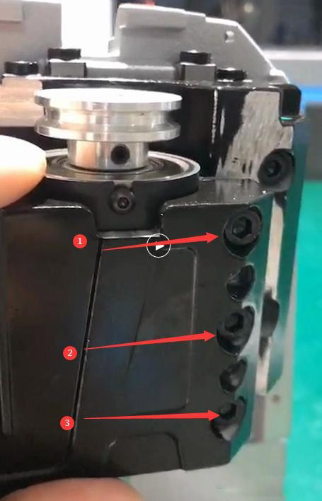
and fasten the two screws until we get a gap to take down the Z-bearing.


Press the cutter’s hole and push the bearing up.
Check if the white paper is broken.
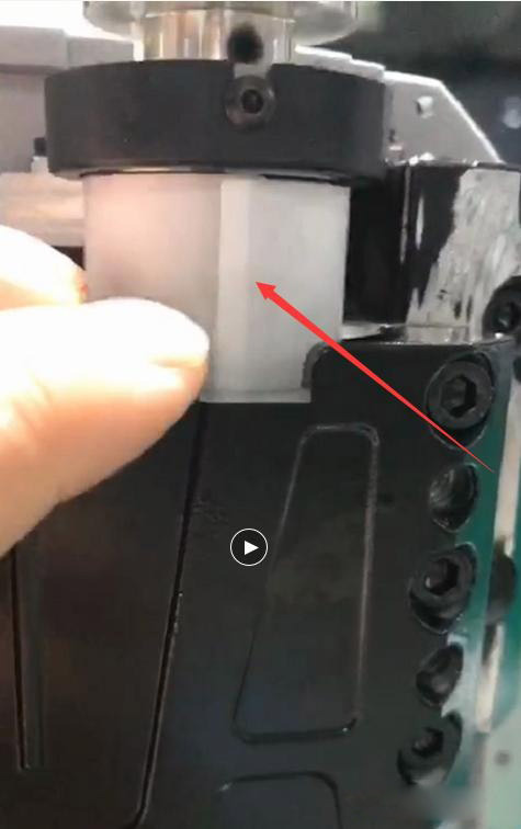
If so, replace it.
If not, check if there are some iron filings inside the bearing hole.
0 notes
Text
How to program 2020 Subaru Impreza by Autel IM608
Autel IM608 Success: 2020 Subaru Impreza push start ign all keys lost 16 min in and out with 2 new smart keys


Don’t you think is it is like a 2k job at the dealer and they rest
0 notes
Text
Ford IDS Testing on Ford Focus by VCM
This is a Ford IDS software on VCM Testing for Ford Focus.
Connect your Focus OBD port to laptop USB port by Ford VCM II.
Then you can find a local connection has already build here.
Run the Ford IDS software on your desktop
If it is your first time to tested with this device,you have to build the connection between cars and the IDS BCM device.
Here we delayed it.
And If it you first time to use this device,you will see here at the right bottom icon to add coins.It means the engine is start.
Note:Please make sure the engine is on,this is very import!
Select “Start New Session”–>Select “All other”
Choose “yes”
Next it will build connection to PCM
System will prompt “Was the vehicle built before March 2008”
Select “No”(According to your cars)
The software will show the VIN number,if it is correct,please select “Yes”
After system reading odometer info,please select “Yes”
It will show the Vehicle information as below:
Vehicle:Focus
Engine Type:DURATEC-HE/14
Capacity:1.8L
PATS:Equipped
Transmission:Manual
Ignition:Integrated EDIS in PCM
Fuel Type:Gasoline
Emission level:All other
VIN:LVSHCAMEX8F325868
Select upper left corner icon for the further diagnosis:
ElectricalàExterior Lighting
Select “Data Link Monitor”
Select “Yes”,at lower right corner
And you can see the level with your lights operations
0 notes
Text
Programming with the Vehicle Intelligence Platform
GM’s new Vehicle Intelligence Platform, or VIP, currently used on 2020-2022 Corvette, CT4, CT5 and 2021-2022 Tahoe, Suburban, Yukon, Escalade and Envision models, offers increased capacity and the ability to better manage technology complexity.
With a fivefold increase in system capacity and responsiveness over the current Global A system, the next-generation VIP electrical architecture offers the capability of managing over 100 computer modules. It’s able to support active safety systems, Over-the-Air (OTA) vehicle software updates, 5G networks, enhanced cybersecurity protections and EV technologies.
The VIP electrical architecture includes two-wire CAN buses and two-wire Ethernet buses to ensure high speed data transfer and multiple single-wire LIN buses to exchange information between master control modules and other smart devices. Low speed General Motors Local Area Network (GMLAN) networks are no longer used in VIP vehicles.
CAN Protocol
The VIP architecture communication protocol is based on the widely used CAN (Controller Area Network) protocol. CAN buses are used where data needs to be exchanged at a high rate, primarily by a control device using the information to adjust a vehicle system, such as powertrain or body controls. Each CAN data network consists of two twisted wires, called CAN (+) and CAN (-), with a 120 ohm (Ω) termination resistor at each end of the bus between the CAN (+) and CAN (-) circuits.
Ethernet data communication technology uses a single twisted copper pair of wires at speeds of 100 Mbit/s and 1000 Mbit/s. The Ethernet system uses point-to-point communication that is connected via an Ethernet switch [Module <–> Switch <–> Module]. The Ethernet bus does not use terminating resistors.
The K56 Serial Data Gateway Module and the A11 Radio have an Ethernet switch that connects to other Ethernet modules. These modules communicate with other devices and systems in the vehicle via CAN and LIN buses. DTCs will be read on CAN to diagnose Ethernet, LIN, and system faults.
Any Ethernet harness failures should be repaired only using the appropriate kit to perform de-pin/re-pin overlays. In cases where the wiring harness repair kits are not available, the entire harness should be replaced. No crimps or splicing should be performed on the Ethernet wiring harness.
Serial Data Gateway
To signal any loss of communication and set DTCs, the K56 Serial Data Gateway Module must know and learn the control modules on the vehicle and their associated buses. If the Serial Data Gateway Module is replaced or another module is added to the bus, such as a dealer-installed accessary, a learn process must be done using the Serial Data Gateway Module learn procedure in SPS.
The learn process will not cause any previously learned contents to be forgotten or overwritten. If the learn process is not completed on a new Serial Data Gateway Module, DTC U1977 (ECU Identification Self Learn Not Completed) will be set until the learn procedure is performed. If the learn process is invalid due to internal malfunction or a Serial Data Gateway Module swap, DTC U3000 42 (Control Module – General Memory Failure) or DTC U3002 56 (Vehicle Identification Number – Invalid/Incompatible Configuration) will be set. The Serial Data Gateway Module will then lose communication with all control modules and set DTCs against control modules not on the vehicle.
The Serial Data Gateway Module also functions as a gateway to isolate the secure networks on the vehicle from unsecured networks. Isolating primary networks helps ensure advanced driver assistance systems and active safety features, such as enhanced collision avoidance, can all operate in conjunction with each other. If harmful software enters the vehicle through the infotainment system, OnStar, or the DLC, other vehicle systems may be affected.
Power Moding
In the VIP architecture, the K9 Body Control Module (BCM) is the Power Mode Master (PMM) and the K56 Serial Data Gateway Module is the back-up PMM. There are five power modes: Off, Accessory, Run/Service Mode (Engine Off), Propulsion (Engine On), and Start. As the PMM, the BCM uses a number of vehicle states and inputs to determine which power mode is required. It reports this information to other modules via serial data.
MDI 2 Required
The EL-52100 GM MDI 2 is required for control module programming, configuration and setup on vehicles equipped with the VIP architecture. The MDI 1 does not have the capability to complete programming and setup procedures. Using an MDI 1 on these vehicles could result in erroneous data or failed programming events that could lead to unnecessary module replacement.
When a scan tool is installed, it will attempt to communicate with every control module that may be available on the vehicle, depending on optional equipment. If an option is not installed on the vehicle, the tool will display No Communication for that control module. In order to avoid misdiagnosis of a No Communication message, refer to the Data Link References that lists the control modules and the buses with which the modules communicate in the appropriate Service Information and the vehicle build RPO codes to determine optional control modules.
Programming a Module
When SPS (Service Programming System) programming a module (Fig. 2), follow all SPS on-screen instructions.

These tips also should will help in successful programming:
Confirm the VIN – Techline Connect (TLC) does not automatically execute the Vehicle Identification Number (VIN) Read with the power mode Off. Technicians must confirm that the VIN is correctly identified prior to programming by verifying the VIN reflected in Techline Connect matches the VIN plate on the vehicle. (Fig. 3) Be sure not to select a VIN that is already in the Techline Connect application memory from a previous vehicle.
To use the VIN Read when using Techline Connect, the vehicle’s power mode (ignition) must be On before reading the VIN from the vehicle’s Engine Control Module (ECM), which is the vehicle’s VIN master module. Programming or reprogramming modules with the incorrect VIN and using software and calibration files from incorrect VINs can cause future serviceability issues as well as potential vehicle performance issues that may require the vehicle to be reprogrammed again.

Battery Voltage – Stable battery voltage is critical during programming. Any fluctuation, spiking, over voltage or loss of voltage will interrupt programming. Install a GM Authorized Programming Support Tool to maintain system voltage. Do not use a battery charger.
Power Mode Off – The power mode (ignition) must be Off to begin module programming. Any load on the vehicle’s battery, such as interior lights, exterior lights and Daytime Running Lamps, and HVAC operation, may affect the download process and may cause errors to occur.
Do Not Change the Power Mode – Do not change the power mode of the vehicle (position of the ignition switch) during the programming procedure unless instructed to do so. Programming will direct the appropriate control module(s) to change power mode as needed during the procedure, independent of the vehicle’s power mode.
Keep Vehicle Fully Asleep – Ensure that the vehicle will not become awake during the programming event by keeping all doors closed (vehicle fully asleep). For access to the vehicle, trip the driver’s door latch to the closed position so that the door can remain open. If a closed door is opened during programming, buses will wake up and cause error codes to set
Clear All DTCs – After programming, clear all DTCs and allow the vehicle to go into sleep mode. DTCs U1962 (Unable to Authenticate Serial Data Message) and U1983 (Serial Data Gateway Module Security Hardware Internal Malfunction) may set and the Check Engine MIL may illuminate if the DTCs are not cleared and the vehicle does not go to sleep after programming or Serial Data Authentication Configuration (SDAC).
If SDAC fails, DTC U1962 will set as a current DTC. It will not clear until another programming event occurs that runs SDAC, or the standalone SDAC procedure is performed using SPS. If DTC U1962 is stored only as a history DTC and not retrieved as a current DTC, do not perform the SDAC procedure.
Wait 5 Minutes – After programming, let the vehicle sit for five minutes with the ignition Off, Retained Accessory Power Off and the key fob removed from the vehicle after completing programming. After five minutes, the system can be operated to verify repairs.
0 notes
Text
How to clearreset DME or EGS Adaptations using INPA
This describes how to clear/reset DME or EGS adaptations using INPA.
Be sure key is in position 2 with engine OFF.
MS43
E46
Engine
MS43
F4 Error
F7 Reset adaptions
F8 adaption Variants clearing
MS45.1
E46
Engine
MS45
F8 adaption
F9 All
GS20, GS8.60.2, GS8.60.4
E46
Transmission
GS20
F6 Activate
F3 Reset adaption values
loading..
If you want to know more information about BMW Diagnostic Tools, please visit our website: Obd2tool.com
0 notes