#6-Axis Force Torque Sensor
Explore tagged Tumblr posts
Visit Tumblr Blog
Explore Tumblr blogs with no restrictions, modern design and the best experience.
Last Seen Tumblr Blogs


Fun Fact
Tumblr was named as a finalist in Lead411’s New York City Hot 125 in Aug 2010.
Text
Industrial Robot 6-axis Force Torque Sensor | AIDIN ROBOTICS
The 6-axis force torque sensor from AIDIN ROBOTICS is a high-precision solution for collaborative robots and industrial robots, designed to accurately measure forces and torques in all six degrees of freedom. This sensor is ideal for improving robotic accuracy and responsiveness, particularly in applications requiring precise control and feedback, such as assembly, grinding, and complex material handling.
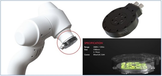
Smart 6-axis Force Torque Sensor
The 6-axis force/torque sensor is an essential component in modern robotics, significantly enhancing wrist performance by detecting tool impacts, managing applied force, and accurately measuring weight. Designed to be attached to the wrist of a collaborative robot, this sensor uses an advanced electrostatic capacitance measurement method, enabling precise force control and collision detection, which are critical for tasks like object weight measurement, force regulation, and teaching applications.
Features of 6-Axis Force/Torque Sensor for Collaborative Robotics:
Next-Generation Measurement Technology: Utilizes a fringe effect-based capacitance measurement method for high-precision force and torque detection.
Integrated IMU: The sensor includes an Inertial Measurement Unit (IMU) to track and remember its position, adding another layer of spatial awareness.
Versatile Communication Options: Supports CAN, EtherCAT, and Ethernet communication protocols for seamless integration into various robotic systems.
Collaborative Robot Compatibility: Specifically designed for integration with collaborative robots, enhancing their performance and safety.
Exceptional Environmental Resistance: Built to withstand challenging environments, with excellent durability.
High-Voltage Protection: Successfully passed a 4kV discharge test, ensuring reliable operation under high electrostatic conditions.
If you are looking for a force torque sensor robot, you can find them at AIDIN Robotics.
Click here to if you are interested in AIDIN Robotics products.
View more: Industrial Robot 6-axis Force Torque Sensor
0 notes
Text
Understanding the Role of 6 Axis Force Sensors in Modern Engineering
In the world of precision engineering and robotics, 6 Axis Force Sensors play a crucial role in providing accurate and comprehensive data about force and torque. These sensors are designed to detect forces and torques along all six degrees of freedom—three translational (X, Y, Z) and three rotational (Rx, Ry, Rz). The technology behind6 Axis Force Sensors is based on advanced strain gauge principles, allowing for highly sensitive and responsive measurements. This makes them essential in applications that demand real-time force feedback and precise control.
Industries such as robotics, aerospace, medical devices, and industrial automation heavily rely on 6 Axis Force Torque Sensor systems for tasks like robotic surgery, haptic feedback, material testing, and automation calibration. These sensors ensure that robots and machines can mimic human-like dexterity, respond to minute environmental changes, and carry out complex tasks with high precision. For instance, in robotic arms used for delicate assembly tasks or surgical procedures, the 6 Axis Force Torque Sensor can detect subtle shifts in force, preventing damage to components or tissues.
Another significant benefit of 6 Axis Force Sensors is their role in enhancing safety and improving efficiency. By providing detailed data on force distribution, they enable engineers to analyze stress points and mechanical behavior under different loads. This helps in refining product designs and avoiding structural failures. Additionally, 6 Axis Force Torque Sensor setups are commonly used in collaborative robots (cobots), where human interaction is frequent. These sensors help cobots sense human touch or obstruction, allowing them to react promptly and safely.
With the increasing trend toward automation and intelligent systems, the demand for high-performance 6 Axis Force Sensors continues to grow. Their compact size, lightweight design, and robust output signals make them suitable for integration into a wide range of platforms, from small medical instruments to large-scale industrial machinery. Moreover, advancements in digital signal processing and miniaturization are making these sensors more accessible and affordable, broadening their application in fields like virtual reality and prosthetics.
In conclusion, 6 Axis Force Sensors and 6 Axis Force Torque Sensor technologies are at the forefront of innovation, enabling a new level of precision and interaction in mechanical systems. Their ability to deliver real-time, multi-directional feedback is transforming the way machines operate, interact, and evolve in an increasingly automated world.
0 notes
Text
The Global Leader in Robot Sensor Technology | AIDIN ROBOTICS

AIDIN ROBOTICS a rapidly evolving robotics company, originated from robotics research conducted by the mechanical engineering department at Sungkyunkwan University. Founded on a strong commitment to innovation and technological excellence, AIDIN Robotics envisions a future where humans and robots coexist and collaborate safely and seamlessly. Central to their mission is the development of cutting-edge robot sensor technologies, drawing on the company’s extensive expertise in field sensing, built since 1995.
With this deep knowledge, AIDIN Robotics is doing new possibilities in human-robot interaction by creating intelligent systems that can precisely find their environment and respond accordingly. With a constant focus on innovation and a passion for technological advancement, AIDIN Robotics aims to lead the way in shaping a future where robotics and human collaboration in the workplace become a reality.
Global Leader in Robot Sensor Technology
AIDIN Robotics is a recognized leader in robot sensor technology, specializing in innovative solutions that enhance human-robot interaction. Their advanced sensor technology includes the smart 6-axis force/torque sensor, which plays a vital role in collision detection, tool weight compensation, and force control. Additionally, the ultra-thin torque sensor offers sensitive measurement capabilities essential for robot joints.
These sensors significantly enhance the functionality and safety of industrial and collaborative robots, positioning AIDIN Robotics as a key player in the robotics industry. Their products are celebrated for their ability to prevent accidents and improve robot adaptability across various industrial environments, underscoring the company’s commitment to developing safer and more intelligent robotic systems.
If you are looking for leading robot sensor technology, you can find it on AIDIN Robotics
Click here to contact AIDIN ROBOTICS View more: Leading Robot Sensor Technology
0 notes

Text
Rack and Pinion Steering
A DRIVER steering a car on a twisting road has two distinct tasks: to match the road curvature, and to keep a proper distance from the lane edges. Both are achieved by turning the steering wheel, but it is not clear which part or parts of the road ahead supply the visual information needed, or how it is used. Current models of the behaviour of real drivers1,2 or 'co-driver' simulators3–5 vary greatly in their implementation of these tasks, but all agree that successful steering requires the driver to monitor the angular deviation of the road from the vehicle's present heading at some 'preview' distance ahead, typically about 1 s into the future. Eye movement recordings generally support this view6–9. Here we have used a simple road simulator, in which only certain parts of the road are displayed, to show that at moderate to high speeds accurate driving requires that both a distant and a near region of the road are visible. The former is used to estimate road curvature and the latter to provide position-in-lane feedback. At lower speeds only the near region is necessary. These results support a two-stage model1 of driver behaviour.
Why do some cars respond so well to the driver? Great handling makes you feel safe and in control – and makes panic swerves and steering corrections as effective as possible. The lightest touch of the wheel should direct the steering system effortlessly and precisely. As well as a well-designed suspension parts, it takes a good quality steering system and steering parts to achieve excellent handling. If you’d like to know the anatomy of a steering system and how it supports handling, road holding and driveability, here is an easy overview.
The function of a steering parts
When you rotate the steering wheel, the car responds. But how does this steering system in cars give you a smooth route forward? A group of parts called the steering system transmits the movement of the steering wheel down the steering shaft to move the wheels left and right – although car wheels don’t turn at the same angle.
The popular rack and pinion steering system
In most cars, small trucks and SUVs on the road today, there is a rack and pinion steering system. This converts the rotational motion of the steering wheel into the linear motion that turns the wheels and guides your path. The system involves a circular gear (the steering pinion) which locks teeth on a bar (the rack). It also transforms big rotations of the steering wheel into small, accurate turns of the wheels, giving a solid and direct feel to the steering.
How does power steering affect the rack and pinion?
It’s likely that if you drive today, you’re used to power steering. Contemporary cars, and especially trucks and utility vehicles have a power steering system function – also called power-assisted steering. This gives that extra energy (either hydraulic or electric) to help turn the wheels and means parking and manoeuvering requires less effort than with simple manual force. The rack and pinion steering system is slightly different with power steering, with an added engine-driven pump or electric motor to aid the steering assembly.
So is ease the only benefit of power steering? The system allows you to have higher gear steering and means you have to turn the steering wheel less to turn the wheels further (less steering wheel turns lock-to-lock). It therefore sharpens up response times and makes the steering even more precise. With such busy roads and traffic jams, this means drivers can more safely manoeuvre in close proximity to other vehicles. Keeping tight control at all speeds, in any conditions and in critical situations, will help to avoid accidents.
What are the components of the steering system in cars?
Whatever a car’s make and model, quality auto steering parts support a flawless drive. Premium rack and pinion parts manufactured by MOOG include axial rods, tie rod ends, drag links, centre arms, steering rack gaiter kits, tie rod assemblies and wheel end bearings.
These steering parts are robust and hard wearing enough to provide both strength and durability. Choosing parts which meet OE manufacturer specifications means the whole assembly will be responsive and long-lasting.
The return of four-wheel steering
Beyond the swivel of the front wheels, some cars have a steering system which affects all four. This has traditionally been exclusive to sporty or luxury models, but there’s a growing trend towards the feature in more affordable cars.
A four-wheel steering control unit sits behind the rear axle of the car and affects the rear wheels as needed. Car wheels turn in opposite directions at low speeds, but at high speeds, turning all four wheels in concert helps to maintain stability and prevent fishtailing.
Stating that automotive literature presents surprisingly little helpful information concerning the faults of the steering-systems used on automotive vehicles and that, in spite of the fact that so many of the faults are self-evident, they frequently are overlooked in actual practice, the author includes with the presentation of his own investigations summaries of the views expressed by numerous well-qualified automotive engineers and discusses these steering-gear faults in some detail. Beginning with the subject of safety, consideration is given successively to the causes of hard steering, the angular position of knuckle-pivots, knuckle-pivot location, the foregather or toe-in of wheels, castering or trailing effect, wheel-wabble, drag-link location, irreversibility, steering-gear type comparisons, tie-rods and tie-rod arms. Numerous drawings illustrative of present-day practice are presented and commented upon, reference being made also to other articles, printed previously, that are pertinent.
Rack and pinion steering systems are not suitable for steering the wheels on rigid front axles, as the axles move in a longitudinal direction during wheel travel as a result of the sliding-block guide. The resulting undesirable relative movement between wheels and steering gear cause unintended steering movements. Therefore only steering gears with a rotational movement are used. The intermediate lever 5 sits on the steering knuckle (Fig. 4.5). The intermediate rod 6 links the steering knuckle and the pitman arm 4. When the wheels are turned to the left, the rod is subject to tension and turns both wheels simultaneously, whereas when they are turned to the right, part 6 is subject to compression. A single tie rod connects the wheels via the steering arm.
Two types of vehicle steering are in general use. The venerable rack-and-pinion system is the simplest and most popular for cars. As the steering wheel is turned, a pinion attached to the base of the steering column moves along a linear-toothed rack to which it is meshed. The arrangement converts the rotary movement of the wheel to a horizontal movement along the transverse axis of the vehicle. The rack is attached at each end to tie rods which transmit the movement to the wheels. This method of steering is positive and provides rapid feedback to the driver. A second steering mechanism, the so-called recirculating-ball system, is used on some heavy trucks and SUVs because of its robustness and greater mechanical advantage. The latter attribute makes turning the wheel easier but, with the advent of power steering, this action is now less of an issue and many heavy vehicles are now adopting rack-and-pinion steering.
Cars with front-wheel drive have much of their weight over the front wheels and therefore it becomes more difficult to turn the steering wheel. This factor, together with the use of wider tyres on SUVs and larger cars, compounds the difficulty to the point that unassisted steering would be almost impossible for many people. Thus most vehicles are today equipped with power steering, a system that is normally operated hydraulically with mineral oil serving as the working medium. A double-acting hydraulic cylinder controls a piston that applies a force to the steering mechanism to augment the effort made by the driver. The pump is operated by a belt-drive off the engine and therefore no assistance is provided unless the engine is switched on. A disadvantage associated with hydraulic power steering is that the pump is constantly running when assistance is not required and this consumes fuel.
An alternative form of power steering is an electrical system in which an electric motor provides assistive torque to the steering mechanism. Sensors detect the position and torque of the steering column and feed the data to a computer that then controls the current to the electric motor. A major advantage of the electrical system is that the degree of assistance can be tailored to the speed of the vehicle, with more assistance at low speeds and less at high speed. Other advantages are: (i) a hydraulic pump, a belt drive and hoses are not required and this leaves more space under the bonnet; (ii) the electrical system is more fuel efficient in that, unlike the hydraulic system, it only uses energy when it is operating.
Some vehicles now have steering on all four wheels. This arrangement was introduced primarily to permit a tighter turning circle and to facilitate parking in a restricted space. It is most useful for truck chassis other parts, heavy goods vehicles and tractors, although it is also available on a few cars. The rear wheels, which cannot turn as far as the front wheels, are controlled by a computer and actuators.
Because thermoplastic elastomers (TPEs) behave essentially as conventional thermoplastics, they can be recycled using the same methods. Many TPEs tolerate multiple recycling [3]. The Society of Automotive Engineers has generically classified commercial TPEs to enable their segregation into mutually compatible categories for recycle purposes [4]. In this scheme, TPEs are categorized in the same manner as that used for rigid thermoplastics such as polypropylene and polystyrene.
TPVs are widely used in automotive applications (e.g., weather stripping, rack-and-pinion steering gear bellows, constant velocity joint boots, air master booster door covers, body plugs, interior skins, etc.) and in appliances (disk drive seals, dishwasher sump boot, door seals, and compressor mounts). The used articles and production scrap are simply ground in a granulator, and the granulate is added in relatively high proportions to the virgin material. The TPV granulate is compatible with granulate prepared from TPO. In fact, it was found that the addition of TPV granulate improves the properties of the TPO material [5]. Many automotive manufacturers have started extensive car dismantling programs and are working together with polymer manufacturers to recycle and reuse material, often in “closed-loop” systems, in which the material goes back into the original product [6].
Other recycling routes for used TPE components are not significantly different from the route for other elastomers, such as incineration with energy recovery. The main benefit of TPEs in this context is that they contain relatively little sulfur, with consequent beneficial effects on incinerator flue gas composition.
Although components made from TPEs can in theory be recycled similar to other thermoplastics, they still suffer from the disadvantage that they are not pure TPEs, but have inserts, or they are composites or blends of materials used in overmolded parts. In the case of the largest class of TPEs, styrenic block copolymers, up to one third of total production is used in inherently nonrecyclable applications, such as oil modifiers, adhesives, or bitumen modification [7].
A recent development that allows recycling of materials from overmolded and coextruded parts is the use of magnetic separation. Magnetic separation is a well-established technique used for high-volume separation in mining, aggregate, and other industries. It is also widely used to remove metal contaminants from plastics and rubber. To be applied for the separation of polymeric materials from mixtures (e.g., TPE from polypropylene or other rigid plastic), it is required that a magnetic additive be mixed into the TPE material. The amount of this additive is typically 1%. It has been established that the additive does not have an adverse effect on the physical properties of the material or on the overmolding adhesion. In the recycling process, the granulated scrap is placed onto a belt conveyor and the particles of the resin with the magnetic additive are separated at the end of the belt by a roll with imbedded powerful rare-earth magnets. The particles attracted to the roll are collected in a hopper after they fall away from it. A mechanical barrier, or “splitter”, helps to separate the two particle streams [8].
0 notes
Text
Overview of Dacell’s Load Cells and Torque Sensors

Dacell's competitiveness is cost-down and customization, we are dreaming of entering the robot industry with multiaxis sensors.
Load cells were first commercialized in the USA and Japan, and they were first developed in Korea 20 or more years ago. Accordingly, it goes too much to say that Dacell has witnessed the history of load cells in the domestic market.
Mr. Shin, Hyeong-Gyun, CEO of Dacell, who has engaged in the development of load cells for a long time, explained that the company’s competitiveness lay in cost down strategy and product customization.
He mentioned how he could enhance brand recognition home and abroad, saying, “The quality of our load cells is almost same as that of American and Japanese competitors, but our prices are very competitive as opposed to them. That is how we could survive in competition with those high-priced products. At the same time, we have tried our best to go far ahead of Chinese companies as far as quality is concerned.”
In addition, Mr. Shin continued to explain the key factors to long-term success, saying “The other competitiveness lies in that we are capable of producing custom-tailored products. Most of time, customers find it difficult to apply general specifications indicated on the catalog to their specific environments; however, we design products to their own requirements. The customization of products that satisfies customers’ needs has been the very reason for us to maintain our business.” torque sensor measuring product
In spite of the presence of various types of load cells, Mr. Shin is developing load cell drawings every day to fill customers’ orders.
Dacell obtained a patent for 3-axes load cell in February, 2010. A normal load cell is used to measure a force on one side, while a three-axis load cell can measure a force of another direction in addition to forces on both sides, namely forces of x, y, and z axes. Additionally, the product group is expanding into 6-axis load cells, which can measure the forces of three directions and the torques of three directions simultaneously. Such multiaxial sensors are currently being supplied to robotics companies.
Mr. Shin made his intention public when he said, “Multiaxial sensors detect toward which direction a biped robot apply or receive forces and help maintain balance in walking.” He continued to say, “We’d like to advance into the robotics industry, but we are still at early stages.”
He added that the company had recently engaged in a research in which rotational power is measured through the data on multidirectional forces which are obtained during driving by multiaxial sensors attached to the wheels of a vehicle. industrial weighing load cells system
Dacell will continue to invest time and sources to develop such target items including multiaxial sensors so as to meet diverse customers’ demands.
0 notes
Text
Iran introduced its most advanced humanoid robot

Little is known about the achievements of Iranian scientists in the field of robotics. Perhaps the most famous was the Surena series of humanoid robots developed by researchers at the University of Tehran. The first model was born just over 10 years ago. Later, improved versions were created - Surena II and Surena III. The latest achievement of Iranian robotics is Surena IV, which was attended by more than 50 researchers led by Professor Agil Yussefi-Coma. According to him, an advanced robot can more accurately track objects, and his new hands have greater dexterity. Custom foot force sensors help Surena move on uneven surfaces by adjusting the angle and position of each leg. Movement speed increased from 0.3 to 0.7 km / h. In its design, it is comparable to some of its more well-known brothers - UBTECH, Walker, Asimo, Talos, Hubo, AIST and HRP-2.

Surena IV has many axes of movement, especially on the arms. The team greatly simplified the design by integrating small but powerful drives into it. As a result, the weight of the new humanoid robot with an increase of 1.7 m was only 68 kg. For comparison, its predecessor Surena III weighed 98 kg with a height of 1.9 m. Another feature is the robot controller. The control loop now runs at a higher frequency (200 Hz), thanks to the FPGA boards. Sensors include stereo cameras, 6-axis ankle force / torque sensors, encoders on all joints, and an inertial measurement unit (IMU). The text-to-speech system allows the robot to recognize people's speech and generate its own response. To make all sensors, controllers, and actuators work together, the researchers equipped Surena IV with their own operating system, ROS. They also used Gazebo, Choreonoid, and MATLAB software to simulate robot movements under various conditions - including walking backwards, sideways, turns and rises after a fall. Read the full article
0 notes
Text
Tuning AFR With Bazzaz
It was time for another round of fine-tuning the fueling on my bike, so I decided to take the time to note some good practices for those who may be new to this.
Fueling Piggybacks
Bazzaz and Power Commander represent a class of bike fueling controllers that depend on the factory ECU to do the majority of the work and sit on it's back, making small adjustments to it's output. In terms of wiring this looks like inline filtering. Coils can also be filtered like this, in Bazzaz's case for TC and QS, but the main benefit of a piggyback is the fueling map, so we're taking interest in injector pulse width here.
Exhibit A (factory): [ECU] ---> factory wiring harness ---> [injector]
Exhibit B (piggyback inline filtering): [ECU] ---> factory wiring harness --> piggyback wiring harness --> [Piggyback ECU] --> piggyback wiring harness --> [injector]
Usually accompanied with a wideband oxygen sensor (a sensor that signals not only if the mixture is rich or lean, but also [B]by how much[/B]), these systems can create 2D maps to hit the desired fueling mixtures, using a logging-based feedback loop. On Power Commander there may now be actual realtime loops, as well as timing adjustment.
Operation Principle For the feedback loop to work correctly, the factory pulse width variance must be locked down, so factory oxygen sensors are replaced with static resistors. For bikes with secondary air injection systems, those ports are blocked off to limit fresh O2 entering the downstream. Once the parameters are locked down, aside from the narrow atmospheric pressure or air temperature deltas, the factory ECU will operate consistently. Proper grounding of the ECU, the piggyback ECU, the resistors and subsequently the wideband O2 sensor is of paramount importance, as impedance will be used to determine fuel trim.
The fundamental method of operation is to use low latency IC electronics to intercept the injector pulse signal. For parts of the map that require more fuel, the IC will immediately send the pulse back out to the output for the injector, but once the factory pulse has stopped, the piggyback will elongate the signal the injector is receiving, keeping the injector open longer, delivering a larger volume of fuel.
Exhibit C and D (factory pulse width VS piggback enriched signal):
----[ ]---- ----[ ]-
For leaning out parts of the map the idea is the same, but since there is no way to know when the injector pulse end from the factory ECU, the piggyback controller instead shaves off the leading edge of the pulse by a predetermined millisecond amount.
Exhibit E and F (factory pulse width VS piggback lean signal):
----[ ]---- ------[ ]----
Good Practices
I have spent what seems now like over a hundred hours tuning the fueling my 1290 Superduke across two different engines, and while this is common knowledge to a lot of tuners, I want to save some of you time and expensive troubleshooting. There are a couple of main areas to pay attention to:
The Baseline
Make sure the bike is in good running order, the following factors will all affect your AFR (air fuel ratios) 1. Clean air filter - no brainer 2. Clean fuel filter - most pumps are easy to get to 3. Well running fuel pump - needs to build correct PSI and maintain it 4. Cleaned, flowed and balanced injectors - at about $18 a pop plus shipping from InjectorRX, it is cheap and effective insurance 5. Freshly adjusted valves - shoot for looser end of OE range as valves will tighten with time 6. Good grounding points - especially on piggyback, factory O2 sensor resistors 7. Check for intake vacuum leaks - inspect rubber throttle body mounts, especially. You are looking for leaks after the TB and before the combustion chamber (unmetered air) 8. Check for secondary air leaks - make sure no oxygen is entering or exhaust gases leaving between the chamber and the O2 wideband
The Process
Measuring and adjusting the fueling with a wideband is not too difficult, but requires patience and diligence. 1. Make sure the ambient air conditions are similar, ideally same. This includes moisture, pressure (or elevation) and temperature. Any factor that affects the oxygen density per unit volume matters. In the Bay Area this will rarely be an actual problem. 2. The dimensions you're working with are RPM range and load range (or a close approximation, like throttle opening percentage). To get a good map, you will want to cover this wide range from start to finish, but stop short of lugging the engine at low RPM, not all cells of the map are ever going to (or should) be visited by the factory ECU. 3. The wideband sensor should defer logging data until it's warmed up automatically. 4. The best way to get good data is to change the load and RPM very slowly, so system latencies have minimum effect and conditions like over-run do not have time to happen. Similarly, avoid traction control, wheelie control, quickshifter, rev-limiter and such from engaging. All of these will alter injector pulse or cut spark and that will affect your readings. 5. Your rear brake is a way to create load without breaking any Mexican speed limits, if you do not have access to a dyno. Check to ensure you have fresh rear pads, you will be surprised how fast those disappear when there's consstently a lot of heat in them, especially with something like my bike that develops 100 ft-lbs of torque. 6. Combined with the previous 2 points, this follows: the best way to get good clean data is on the dyno, in my experience. Second best is on the highway somewhere in Mexico, third best is on the track or on the street.
The Adjustment
If you're not using Power Commander realtime autotune, or if you're working with a real tuner, you will need to do the aiming yourself. 1. Develop an idea of target AFRs. To keep things straightforward you may want to pick one value for the entire map. As you experiment with that value, you will likely want to change it progressively from low-load to high-load. For shitty motors or weird cases, you will find area in the low or high RPM range where you will want to adjust it further. Different fuels will have different air requirements, the following assumes premium pump gas. ICE develop their best power somewhere in the range of 12-13.7, however, you will find that throttle response can be wildly different within it. As can be longtail reliability. Richer end (12 units of air per unit of liquid fuel) tends to work well for stressed or endurance engines, think sustained load during racing, forced induction engines, air cooled engines - it will make the combustion cooler. Also it happens to provide the smoothest, even if at times delayed throttle response. The leaner end of things (13.7 AFR) will give you snappier and jerkier throttle response and will make the combustion chamber and exhaust gases a bit hotter.
In my particular case, I use a 1-dimensional gradient across the load axis on my 2015 Superduke R 1301cc engine. I start at 13.4 AFR all the way at the bottom of 0-4% opening and use that AFR all the way until 50% load. From 50% load to 100% load I enrich it progressively from 13.4 AFR to 12.8 AFR. This suits my reliability and throttle response preferences. 2. Your software will want to tell you what you should adjust the fuel map to (automatically) to hit the desired AFR. I do not have good luck with this guesses process because for some reason for me it always ends up being an over-correction oscillation dance that would eventually converge. What I do instead is approach the desired AFR in steps. So if the software math is saying to enrich by 10 points, I will generally enrich by 5 points, then go out and measure again. 3. Discard any obvious outliers. No good fuel map and engine will have sudden jumps in fueling requirements. If you see dramatically lean values (sudden jumps from 13 AFR to 14 and lower), the engine may have cut spark, cut fuel or you hit an over-run condition. Do not touch the affected cells, go out and re-measure again. 4. In my case, Bazzaz does not collect data for the lowest tier of throttle load (0-4% range), the bottom most row. For extra exhaust pops, extra smooth on\off throttle transitions and reduced engine braking, I like to manually enrich this row to half of what the next row up is, numerically speaking. 5. The general wisdom is: if something looks weird, ignore the data and re-measure. When it doubts, make adjustments small, not larger. When on the fence, especially in high load parts of the map, go a little bit richer - it's safer for throttle inputs and for engine longevity. 6. With time you will start developing good intuition: you will notice the engine sounds differently when it's too rich, you will notice how twitchy the throttle is during lean condition.
The Debrief
Write down what you did and how you did it. Something will happen to your bike and you will want to know what our baseline represents. This can be injectors clogging, you experimenting with different plugs, you upgrading intake or exhaust or simply doing your valves. 1. Wideband oxygen sensors have limited life. Take the unit off your bike including supporting logging module and wiring harness. Save it for later. 2. Create a folder structure for that day's tuning resulting map. Note the target AFRs, note the atmospheric conditions, not the mileage and what your valves were set to. 3. If you have previous maps, do a map delta comparison to ensure the adjustments make sense. You can spot deteriorating valve clearances, dirty air filter, fouled plugs, bad injector spray pattern or a faulty oxygen sensor early this way.
Bonus Round
If you use Bazzaz and you get into this, you will likely burn up their oxygen sensor over the long run. Do not rush to give them $150 plus S\H for a new one. Their systems are based on industry standard Bosch 4.2 (closed air cell system) and Bosch 4.9 (new gen) wideband tuning technology. Standard off the shelf sensors will work, but ensure to match the connector.
In my case, I use the 4.2 system and I verified that Bosch 17018, is in fact, correct. At the time of me writing this it was $67 on Amazon and was Original Equipment part for some Subarus. Bazzaz themselves order these oxygen sensors in bulk from a third party supplier that does not stamp or mark them, making that whole hunt a huge pain in the ass for me, but I confirmed my findings with a Bazzaz tech. So save your valuable time and money.
Incomplete list of sources:
AutoSpeed - Tuning Air/Fuel Ratios http://www.autospeed.com/cms/article.html?&title=Tuning-AirFuel-Ratios&A=1595
Master Engine Tuner - Air-Fuel Ratio Tuning Tips http://www.masterenginetuner.com/air-fuel-ratio-tuning-tips.html
Amazon - Bosch 17018 4.2 LSU https://www.amazon.com/gp/product/B000BZL0LC/ref=ppx_yo_dt_b_search_asin_title?ie=UTF8&psc=1
KTM 1290 SMR - My dope bike if you haven't seen it https://www.1290smr.com/
0 notes
Text
The New DJI Robot is Insane: Introducing the Robomaster EP Core
Our verdict of the DJI Robomaster EP Core: The most powerful STEAM learning robot ever. A comprehensive education toolkit and curriculum for both Scratch and Python programming is provided, and further expansion is possible with various microcontrollers and sensors.1010
You probably think of DJI as that drone company, but they’ve actually turned their engineering geniuses to a lot more than just drones. The DJI Robomaster EP Core is the next generation of intelligently programmable, remote-controlled, or entirely autonomous robots. It’s insanely good fun, a great learning experience, and I’m completely smitten with it.
Read on to find out more.
Robomaster EP Core: At a Glance
Omnidirectional movement via Mecanum wheels and custom servo motors with 250Nmm torque.
Four hit detectors (impact or laser) with RGB ring lights.
2-axis grabber.
2400mAh battery (around 1-hour battery life).
HD camera, microphone, and onboard speaker.
Micro-SD card slot.
Local Wi-Fi or router connectivity.
Proximity sensor.
Dimensions: H13 x W10 x L15.5 inches (H33 x W25 x L39 cm) with grabber fully retracted.
Weight: 7lbs 8oz (3.4kg).
Expandable with Raspberry Pi, Arduino, micro:bit, or NVIDIA Jetson; sensor adaptors provided.
FPV remote control via desktop or smartphone app.
Scratch or Python programming.
Curriculum and structured competitive modes.
Note: we received an engineering sample for testing. Contents and build guide may differ, and we didn’t have access to the full educational curriculum, only the existing Robomaster app (which is primarily designed for the Robomaster S1 Series).
Building the Robomaster EP Core
Before you can really get started, the Robomaster EP Core package arrives in an enormous box consisting of five trays of parts. That’s right: it’s flat-packed and you’ll need to build it yourself. That would the Engineering part of the STEAM learning experience.
It took me a good half-day of solid build time to get this put together (which you can see in the video review compressed down to about a minute!).
Thankfully the instructions are detailed, and despite two full trays of screws and bolts, each part is labeled well and at no point was I confused about where something ought to be placed.
If you can build some Ikea furniture, you can do this. Just be sure to pick the right screw from the right part of the tray.
Getting Started
You can connect to the Robomaster either via a local Wi-Fi, or by allowing the Robomaster to connect to your router. The latter is preferable, as it allows you to access the Robomaster from any networked client for truly remote control and programming.
A desktop version of the software is available for Mac or PC, though it appears to be a direct port of the mobile app, and runs full-screen.
A switch on the side of the grey controller box selects which mode to operate in. Simply type in your Wi-Fi password to the app so it can generate a QR code. The camera mounted on the Robomaster will then read this, and connect to the network.
Note that the Robomaster is unable to roam between enterprise Wi-Fi access points, so you should use a single high powered router or ensure adequate coverage in the location you’ll be operating the Robomaster. Driving down my hallway resulted in the Robomaster disconnecting from one Unifi access point and pausing for a few seconds as it reconnected through another.
Robomaster Chassis
There are two main parts to the build. The first is the wheels and chassis. We’ll talk more about the “Mecanum” wheels in a moment, but the chassis itself is built around a large solid metal frame, which includes extra mounting points for your own 3D printed parts, accessories, or additional sensors.
The front half has a slight suspension on it, allowing it to traverse small bumps with ease.
This chassis houses the battery as well as the power distribution board and communication bus. It’s this that you’ll plug everything in to. The battery is removable, and spares can be purchased. Each charge lasted me about an hour of constant use.
The 2400mAh battery can be swapped easily and spares purchased separately.
One outstanding feature of the Robomaster EP Core is the four Mecanum wheels. Each wheel is driven by its own powerful custom DJI servo.
Rather than a traditional rubber tire, these wheels has a set of twelve freely-rotating rollers, mounted at a 45-degree offset. Confused? I don’t blame you.
This curious arrangement of rollers on the wheel means that simply rotating the wheel actually forces it to move sideways instead. In order to create the normal forward or backward motion, you need another Mecanum wheel with its rollers mounted in the opposite direction. When both wheels are then rotated in the same direction, the sideways forces cancel each other out, and the chassis actually moves forward or backward as intended.
However, the magic comes when each wheel is driven in opposite directions, both creating the same sideways motion instead. With four such wheels mounted in this configuration, the Robomaster can both strafe left and right, and rotate 360-degrees on the spot. This is called omnidirectional movement. And it’s nothing short of amazing.
If you haven’t already watched the review video to see this in action, you really need to go do that now. Go on, I’ll wait.
This isn’t just incredible to watch though, it also opens up so many more programming possibilities for maneuvering because of the precision involved.
It also adds more interest to the remote control aspect. Maneuvering now requires two analog joysticks, rather than an accelerate and brake pedal, and steering wheel. Anyone familiar with first-person shooter games will feel at home immediately. You can strafe around a target in a circle, for instance, or easily drift around corners. The Robomaster EP Core is highly agile in tight spaces, and racing this thing is immensely fun.
Stop having fun though: this is a learning experience!
Grabber
Mounted on top of the chassis are the grabber attachment and grey controller box. The controller handles Wi-Fi communication, as well as the micro-SD card for recordings.
Powered by three strong servos, the grabber can lift up and down, push or pull, as well as pinch in or expand its rubber claws. Obviously the first thing I did was to grab a courgette and lug it around the kitchen for a while.
This is a screenshot from a video taken using the on-board camera.
When fully extended, the lifting power of the servo is limited, so you may need to pull an object in closer before it can be lifted up again. It’s reasonably powerful and was able to lift up some small blocks of wood or toy cones, but struggled with an iPhone 6 Plus (which is about 6 ounces).
Robomaster doing a spot of weeding with the grabber.
The Robomaster App
While a separate SDK is available and will likely be used for parts of the curriculum, your initial point of contact with the robot will be via the Robomaster app (for iOs, Android, Mac, or Windows). Launch this and you’ll be greeted with three choices:
Solo
Battle
Lab
Solo mode is for simple remote control. Use the joystick on the left to move forward, backward, and strafe. Drag left or right on the screen to rotate. Click the grabber button to bring up that control interface. The main screen area is taken up by the wide-angle first-person-view from Robomaster’s camera. You can also record a number of audio clips to playback on the robot. These are saved to the hardware and can be recalled or set on a loop with hilarious consequences.
The button for follow mode sadly does nothing without the gimbal attached. To move the camera view up or down, you’ll need to manipulate the grabber arm that it’s attached to. The health bar also doesn’t do much unless you’re being pursued by a Robomaster S1 equipped with a laser gun (not even kidding–that’s a thing).
Battle mode is a more structured FPV combat or race event. Without the gimbal and gel bead or laser gun, the battle type aren’t relevant, but the race mode can still be used. By placing the included visual markers around your track, Robomasters must visit each marker in order, which behave as checkpoints. A bonus marker can also be hidden for extra points. The AI recognition system will immediately identify any it sees (though I found this only worked with good lighting), and after visiting each one in turn for the required number of laps, you’re given a resulting time.
Camera and FPV
Unsurprisingly for a company known to produce superb quality video drones, the FPV camera mounted on top of the grabber is also superb.
With an f2.4 aperture and wide 120-degree field of view, I found video transmission to be rock solid and perfectly clear, though this will depend largely on your router and Wi-Fi performance. You can record HD video to a micro-SD card too (not included), which includes audio.
A screengrab from the on-robot camera.
Finally, the Lab is where you can learn all the Robomaster functions, as well as jump right into Python or Scratch coding. Road to Mastery consists of 11 guided Scratch tutorials. DIY Programming presents you with some ready-made Python or Scratch code examples or allows to start afresh. Robo Academy is really just three web links, taking you directly the developer documentation, video tutorials, and programming guide.
Again though, many of these resources rely on the gimbal attachment, so I wasn’t able to fully complete all of these with the EP Core. They’re still beneficial to run through however, and you may find you can convert many of the instructions for use with the grabber alone. The curriculum included with EP Core purchases will be tailored to the grabber.
Scratch Programming the Robomaster EP Core
Now taught to all school children from primary ages and up, Scratch is a visual block programming language that’s surprisingly powerful. The custom Robomaster GUI includes buttons to either bring up a first-person view (to drive the robot back tot he start position before running code again, for instance), and a debug overview of currently defined variables. As the robot runs through programs, blocks of code are highlighted, so it’s easy to follow along and see exactly what’s going on. You can even convert your Scratch program to Python code at any point if you’d rather.
I haven’t actually used Scratch before–the best I had in school was some a BBC Micro Turtle, with BASIC programming. I was pleasantly surprised at how easy it is to pick up, and how much of the Robomaster’s systems are exposed to graphical programming. The “Smart” block section includes things like action for when a visual marker is recognized in view, or when a number of claps are identified.
Robomaster S1 vs EP Core
Robomaster S1 was released last year and is available to purchase for all consumers. It features the same Mecanum wheeled chassis as the EP Core, but doesn’t have as any extensibility when it comes to additional power ports, sensor adaptors, or communications facilities for Arduino, micro:bit, or Raspberry Pi. It’s a more simple remote control and programmable robot, than an entire engineering platform.
The most noticeable difference is that the S1 featured a gel-bead and laser shooter mounted on a gimbal (“Warrior mode”), which could be used for Robomaster battles, or to shoot the included vision marker targets.
Instead, the EP Core instead uses a more education-focused (or school-friendly) grabber attachment, which DJI calls “Engineering mode”.
The EP Core also has a full curriculum for all suitable year groups to follow (though we haven’t had access to that so can’t comment further on it).
While many of the Robomaster app tutorials are currently reliant on having the gimbal attachment, the remote control element and programming components are all there for use with the grabber.
The other difference is pricing: Robomaster S1 can be purchased for around $500 from numerous stockists. The EP Core is only available through educational partners, or via direct inquiry to DJI. I couldn’t draw them on exact pricing (presumably there are bulk discounts for schools), but given the similarity to the S1, I wouldn’t have thought it was too far off the $500 mark.
Robomaster S1 Robomaster S1 Buy Now On Amazon $549.00
Is This the Ultimate STEAM Learning Tool?
In a word, yes.
The only slight frustration is that you can’t currently follow all of the Robomaster app tutorials. It’s not clear if these will be expanded to cover more of the grabber functionality, but the full curriculum will be tailored toward it and included with all purchases.
I’m quite envious of any lucky students who have the opportunity to learn to program using the EP Core. It’s simply an incredible learning tool. Sure you could learn Scratch without a cool robot to drive around, but it’s a whole lot more motivating to have that real hardware react to your programming. The EP Core model includes expansion ports and mounting holes for additional sensors and development boards, such as the Raspberry Pi, Arduino, or even NVIDIA’s Jetson Nano.
For pricing, you’ll need to enquire directly with DJI or via their local educational providers. Alternatively, if the expansion capabilities aren’t a concern and you’d rather the gimbal-mounted gel-bead and laser shooter instead of a grabber, check out the Robomaster S1, which is widely available.
Read the full article: The New DJI Robot is Insane: Introducing the Robomaster EP Core
The New DJI Robot is Insane: Introducing the Robomaster EP Core posted first on grassroutespage.blogspot.com
0 notes
Text
Leader of Global Robot Sensor Market | AIDIN ROBOTICS
The evolving robotic company AIDIN ROBOTICS Inc. has begun in robotics research carried out by Sungkyunkwan University's mechanical engineering department. Established on a foundation of innovation and technological excellence, AIDIN ROBOTICS is dedicated to realizing a future where people and robots seamlessly coexist and collaborate in a safe manner. At the core of AIDIN ROBOTICS’ mission is the development of advanced robot sensor technologies, building upon the extensive field sensing expertise the company has accumulated since 1995.
[Robot Sensor Market Analysis]
Global Market for 6-Axis Force/Torque Sensors for Robots
Out of the global robot sensor market worth 2.4 trillion KRW, the 6-axis force/torque sensor segment represents 25%, forming a market valued at approximately 600 billion KRW. It is projected to grow by 13% annually, reaching 1.105 trillion KRW by 2028.
Demand Forecast for 6-Axis Force/Torque Sensors Based on Industrial Processes
[1]
Based on the number of robots introduced into these processes, the global demand for 6-axis force/torque sensors in 2022 is estimated at around 90,000 units. With the global sensor market’s 13% CAGR, the worldwide demand is expected to grow to 165,000 units by 2026.
Forecast for 6-Axis Force Torque Sensor Demand in the Growing Collaborative Robot Market
While collaborative robots (cobots) are primarily being adopted by small and medium-sized manufacturers for cost-effective and safe operations with simple position control processes, future demand for competitive 6-axis force/torque sensors is expected to increase, as these sensors will enable force/torque-based operations without the need for expensive ATI sensors traditionally used in industrial robots.
As of 2020, in the domestic market, 10.3% of small and medium-sized manufacturers (3,060 out of 30,602 companies) expressed an intention to introduce robots. Of these, 34% (1,040 companies) are expected to adopt processes that require 6-axis force/torque sensors.
With the growth of the collaborative robot market, the number of companies requiring 6-axis force/torque sensors is projected to increase to 8,893 by 2026.
Expansion Strategy for EoAT+Solutions Utilizing 6-Axis Force/Torque Sensors
Expanding into solutions that integrate sensors with End-of-Arm Tooling (EoAT) is expected to generate sales for each process that uses 6-axis force/torque sensors. This would create a high value-added business, potentially 50 times more profitable than selling individual sensors alone.
In the future, most of the processes that have yet to be automated by robots involve tasks requiring skilled manual labor and the application of force. This suggests that the remaining automatable processes will largely rely on 6-axis force/torque sensors and EoAT solutions.
If you are looking for world's leading robot sensor technology company, you can find it on Aidin Robotics
Click here to contact AIDIN ROBOTICS.
View more: Leader of Global Robot Sensor Market
0 notes
Text
Understanding the Role of 3 Axis Force Sensor in Modern Engineering and Robotics
In the realm of precision measurement and advanced robotics, the 3 axis Force Sensor has become an essential component for capturing accurate and dynamic force data across three orthogonal directions—X, Y, and Z. These sensors are widely used in applications ranging from industrial automation and robotic gripping to biomechanics and aerospace engineering. The ability to detect subtle variations in applied force helps engineers, scientists, and technicians optimize systems for performance, safety, and efficiency.
Aᅠ3 axis Force Sensor works by converting mechanical force into an electrical signal through strain gauges or piezoelectric elements embedded in its structure. The sensor measures forces along the three Cartesian axes, enabling the detection of not just the magnitude but also the direction of the applied force. This is particularly useful in robotic arms, where the sensor can help determine how much pressure is applied during gripping, assembly, or surgical procedures. The result is a much higher level of control and feedback, which enhances the functionality of intelligent systems.
When comparing sensor technologies, one of the most significant developments beyond theᅠ3 axis Force Sensor is the evolution of 6 Axis Force Sensors. These devices add the ability to detect torque (rotational forces) around each of the three axes, offering a full six degrees of freedom. While 3 axis Force Sensors are excellent for detecting linear forces, 6 Axis Force Sensors are necessary in applications that require complex interaction, such as humanoid robots, prosthetics, and virtual reality feedback systems. They provide a holistic picture of both linear and rotational forces, enabling machines to respond with even more human-like sensitivity and motion.
The compact design and robust construction of aᅠ3 axis Force Sensor make it ideal for integration into small spaces without sacrificing performance. These sensors are often made with high-strength materials such as stainless steel or titanium, ensuring reliability in challenging environments. Additionally, many models are equipped with signal conditioning circuits, digital outputs, and compatibility with data acquisition systems, making them easy to deploy in a variety of settings.
In testing and quality control environments,ᅠ3 axis Force Sensors provide real-time data that allows manufacturers to assess product strength, endurance, and safety standards. For example, in automotive crash testing, they can measure the precise force impacts on vehicle structures or dummies. In sports biomechanics, these sensors can be mounted on shoes or equipment to analyze how athletes apply force during performance, leading to better training and injury prevention.
Furthermore, the integration ofᅠ3 axis Force Sensor technology into medical devices has transformed procedures such as robotic-assisted surgery. Surgeons gain haptic feedback, enabling more delicate and controlled movements during operations. This innovation reduces risks and improves patient outcomes, especially in minimally invasive techniques.
While 3 axis Force Sensors are sufficient for many linear force measurement applications, industries pushing the boundaries of automation and precision often require the extended capabilities of 6 Axis Force Sensors. Whether it’s for delicate touch sensing in prosthetic limbs or for accurate force feedback in advanced simulation systems, both types of sensors play pivotal roles in the next generation of intelligent systems.
As industries move toward more sophisticated automation and intelligent devices, the demand for high-precision, multi-directional force measurement will continue to grow. The 3 axis Force Sensor, with its accuracy, durability, and adaptability, remains a cornerstone of modern measurement systems. Meanwhile, the broader functionality of 6 Axis Force Sensors expands the possibilities for machines to perceive and interact with the physical world in more nuanced and dynamic ways
0 notes
Text
The New DJI Robot is Insane: Introducing the Robomaster EP Core
Our verdict of the DJI Robomaster EP Core: The most powerful STEAM learning robot ever. A comprehensive education toolkit and curriculum for both Scratch and Python programming is provided, and further expansion is possible with various microcontrollers and sensors.1010
You probably think of DJI as that drone company, but they’ve actually turned their engineering geniuses to a lot more than just drones. The DJI Robomaster EP Core is the next generation of intelligently programmable, remote-controlled, or entirely autonomous robots. It’s insanely good fun, a great learning experience, and I’m completely smitten with it.
Read on to find out more.
Robomaster EP Core: At a Glance
Omnidirectional movement via Mecanum wheels and custom servo motors with 250Nmm torque.
Four hit detectors (impact or laser) with RGB ring lights.
2-axis grabber.
2400mAh battery (around 1-hour battery life).
HD camera, microphone, and onboard speaker.
Micro-SD card slot.
Local Wi-Fi or router connectivity.
Proximity sensor.
Dimensions: H13 x W10 x L15.5 inches (H33 x W25 x L39 cm) with grabber fully retracted.
Weight: 7lbs 8oz (3.4kg).
Expandable with Raspberry Pi, Arduino, micro:bit, or NVIDIA Jetson; sensor adaptors provided.
FPV remote control via desktop or smartphone app.
Scratch or Python programming.
Curriculum and structured competitive modes.
Note: we received an engineering sample for testing. Contents and build guide may differ, and we didn’t have access to the full educational curriculum, only the existing Robomaster app (which is primarily designed for the Robomaster S1 Series).
Building the Robomaster EP Core
Before you can really get started, the Robomaster EP Core package arrives in an enormous box consisting of five trays of parts. That’s right: it’s flat-packed and you’ll need to build it yourself. That would the Engineering part of the STEAM learning experience.
It took me a good half-day of solid build time to get this put together (which you can see in the video review compressed down to about a minute!).
Thankfully the instructions are detailed, and despite two full trays of screws and bolts, each part is labeled well and at no point was I confused about where something ought to be placed.
If you can build some Ikea furniture, you can do this. Just be sure to pick the right screw from the right part of the tray.
Getting Started
You can connect to the Robomaster either via a local Wi-Fi, or by allowing the Robomaster to connect to your router. The latter is preferable, as it allows you to access the Robomaster from any networked client for truly remote control and programming.
A desktop version of the software is available for Mac or PC, though it appears to be a direct port of the mobile app, and runs full-screen.
A switch on the side of the grey controller box selects which mode to operate in. Simply type in your Wi-Fi password to the app so it can generate a QR code. The camera mounted on the Robomaster will then read this, and connect to the network.
Note that the Robomaster is unable to roam between enterprise Wi-Fi access points, so you should use a single high powered router or ensure adequate coverage in the location you’ll be operating the Robomaster. Driving down my hallway resulted in the Robomaster disconnecting from one Unifi access point and pausing for a few seconds as it reconnected through another.
Robomaster Chassis
There are two main parts to the build. The first is the wheels and chassis. We’ll talk more about the “Mecanum” wheels in a moment, but the chassis itself is built around a large solid metal frame, which includes extra mounting points for your own 3D printed parts, accessories, or additional sensors.
The front half has a slight suspension on it, allowing it to traverse small bumps with ease.
This chassis houses the battery as well as the power distribution board and communication bus. It’s this that you’ll plug everything in to. The battery is removable, and spares can be purchased. Each charge lasted me about an hour of constant use.
The 2400mAh battery can be swapped easily and spares purchased separately.
One outstanding feature of the Robomaster EP Core is the four Mecanum wheels. Each wheel is driven by its own powerful custom DJI servo.
Rather than a traditional rubber tire, these wheels has a set of twelve freely-rotating rollers, mounted at a 45-degree offset. Confused? I don’t blame you.
This curious arrangement of rollers on the wheel means that simply rotating the wheel actually forces it to move sideways instead. In order to create the normal forward or backward motion, you need another Mecanum wheel with its rollers mounted in the opposite direction. When both wheels are then rotated in the same direction, the sideways forces cancel each other out, and the chassis actually moves forward or backward as intended.
However, the magic comes when each wheel is driven in opposite directions, both creating the same sideways motion instead. With four such wheels mounted in this configuration, the Robomaster can both strafe left and right, and rotate 360-degrees on the spot. This is called omnidirectional movement. And it’s nothing short of amazing.
If you haven’t already watched the review video to see this in action, you really need to go do that now. Go on, I’ll wait.
This isn’t just incredible to watch though, it also opens up so many more programming possibilities for maneuvering because of the precision involved.
It also adds more interest to the remote control aspect. Maneuvering now requires two analog joysticks, rather than an accelerate and brake pedal, and steering wheel. Anyone familiar with first-person shooter games will feel at home immediately. You can strafe around a target in a circle, for instance, or easily drift around corners. The Robomaster EP Core is highly agile in tight spaces, and racing this thing is immensely fun.
Stop having fun though: this is a learning experience!
Grabber
Mounted on top of the chassis are the grabber attachment and grey controller box. The controller handles Wi-Fi communication, as well as the micro-SD card for recordings.
Powered by three strong servos, the grabber can lift up and down, push or pull, as well as pinch in or expand its rubber claws. Obviously the first thing I did was to grab a courgette and lug it around the kitchen for a while.
This is a screenshot from a video taken using the on-board camera.
When fully extended, the lifting power of the servo is limited, so you may need to pull an object in closer before it can be lifted up again. It’s reasonably powerful and was able to lift up some small blocks of wood or toy cones, but struggled with an iPhone 6 Plus (which is about 6 ounces).
Robomaster doing a spot of weeding with the grabber.
The Robomaster App
While a separate SDK is available and will likely be used for parts of the curriculum, your initial point of contact with the robot will be via the Robomaster app (for iOs, Android, Mac, or Windows). Launch this and you’ll be greeted with three choices:
Solo
Battle
Lab
Solo mode is for simple remote control. Use the joystick on the left to move forward, backward, and strafe. Drag left or right on the screen to rotate. Click the grabber button to bring up that control interface. The main screen area is taken up by the wide-angle first-person-view from Robomaster’s camera. You can also record a number of audio clips to playback on the robot. These are saved to the hardware and can be recalled or set on a loop with hilarious consequences.
The button for follow mode sadly does nothing without the gimbal attached. To move the camera view up or down, you’ll need to manipulate the grabber arm that it’s attached to. The health bar also doesn’t do much unless you’re being pursued by a Robomaster S1 equipped with a laser gun (not even kidding–that’s a thing).
Battle mode is a more structured FPV combat or race event. Without the gimbal and gel bead or laser gun, the battle type aren’t relevant, but the race mode can still be used. By placing the included visual markers around your track, Robomasters must visit each marker in order, which behave as checkpoints. A bonus marker can also be hidden for extra points. The AI recognition system will immediately identify any it sees (though I found this only worked with good lighting), and after visiting each one in turn for the required number of laps, you’re given a resulting time.
Camera and FPV
Unsurprisingly for a company known to produce superb quality video drones, the FPV camera mounted on top of the grabber is also superb.
With an f2.4 aperture and wide 120-degree field of view, I found video transmission to be rock solid and perfectly clear, though this will depend largely on your router and Wi-Fi performance. You can record HD video to a micro-SD card too (not included), which includes audio.
A screengrab from the on-robot camera.
Finally, the Lab is where you can learn all the Robomaster functions, as well as jump right into Python or Scratch coding. Road to Mastery consists of 11 guided Scratch tutorials. DIY Programming presents you with some ready-made Python or Scratch code examples or allows to start afresh. Robo Academy is really just three web links, taking you directly the developer documentation, video tutorials, and programming guide.
Again though, many of these resources rely on the gimbal attachment, so I wasn’t able to fully complete all of these with the EP Core. They’re still beneficial to run through however, and you may find you can convert many of the instructions for use with the grabber alone. The curriculum included with EP Core purchases will be tailored to the grabber.
Scratch Programming the Robomaster EP Core
Now taught to all school children from primary ages and up, Scratch is a visual block programming language that’s surprisingly powerful. The custom Robomaster GUI includes buttons to either bring up a first-person view (to drive the robot back tot he start position before running code again, for instance), and a debug overview of currently defined variables. As the robot runs through programs, blocks of code are highlighted, so it’s easy to follow along and see exactly what’s going on. You can even convert your Scratch program to Python code at any point if you’d rather.
I haven’t actually used Scratch before–the best I had in school was some a BBC Micro Turtle, with BASIC programming. I was pleasantly surprised at how easy it is to pick up, and how much of the Robomaster’s systems are exposed to graphical programming. The “Smart” block section includes things like action for when a visual marker is recognized in view, or when a number of claps are identified.
Robomaster S1 vs EP Core
Robomaster S1 was released last year and is available to purchase for all consumers. It features the same Mecanum wheeled chassis as the EP Core, but doesn’t have as any extensibility when it comes to additional power ports, sensor adaptors, or communications facilities for Arduino, micro:bit, or Raspberry Pi. It’s a more simple remote control and programmable robot, than an entire engineering platform.
The most noticeable difference is that the S1 featured a gel-bead and laser shooter mounted on a gimbal (“Warrior mode”), which could be used for Robomaster battles, or to shoot the included vision marker targets.
Instead, the EP Core instead uses a more education-focused (or school-friendly) grabber attachment, which DJI calls “Engineering mode”.
The EP Core also has a full curriculum for all suitable year groups to follow (though we haven’t had access to that so can’t comment further on it).
While many of the Robomaster app tutorials are currently reliant on having the gimbal attachment, the remote control element and programming components are all there for use with the grabber.
The other difference is pricing: Robomaster S1 can be purchased for around $500 from numerous stockists. The EP Core is only available through educational partners, or via direct inquiry to DJI. I couldn’t draw them on exact pricing (presumably there are bulk discounts for schools), but given the similarity to the S1, I wouldn’t have thought it was too far off the $500 mark.
Robomaster S1 Robomaster S1 Buy Now On Amazon $549.00
Is This the Ultimate STEAM Learning Tool?
In a word, yes.
The only slight frustration is that you can’t currently follow all of the Robomaster app tutorials. It’s not clear if these will be expanded to cover more of the grabber functionality, but the full curriculum will be tailored toward it and included with all purchases.
I’m quite envious of any lucky students who have the opportunity to learn to program using the EP Core. It’s simply an incredible learning tool. Sure you could learn Scratch without a cool robot to drive around, but it’s a whole lot more motivating to have that real hardware react to your programming. The EP Core model includes expansion ports and mounting holes for additional sensors and development boards, such as the Raspberry Pi, Arduino, or even NVIDIA’s Jetson Nano.
For pricing, you’ll need to enquire directly with DJI or via their local educational providers. Alternatively, if the expansion capabilities aren’t a concern and you’d rather the gimbal-mounted gel-bead and laser shooter instead of a grabber, check out the Robomaster S1, which is widely available.
Read the full article: The New DJI Robot is Insane: Introducing the Robomaster EP Core
The New DJI Robot is Insane: Introducing the Robomaster EP Core published first on http://droneseco.tumblr.com/
0 notes
Text
Innovative Technology and Design Robotic Smart Gripper System | AIDIN ROBOTICS

AIDIN ROBOTICS Inc. Smart Gripper is a robotic gripping system designed with several advanced features that enhance its functionality across various industries. A smart gripper is a robotic end-effector equipped with sensors and advanced control systems that enable it to adapt to various objects and environments. Unlike traditional grippers, which are often limited to handling specific shapes or sizes, smart grippers can grasp and manipulate a wide range of items with greater precision and flexibility.
AIDIN ROBOTICS' Smart Gripper System
AIDIN ROBOTICS offers a comprehensive robotic gripper system that combines cutting-edge technology and innovative design to meet the diverse needs of industrial applications. Key features and benefits of their system include:
Advanced Sensing Capabilities:
Force/Torque Sensors: Precisely measure the forces and torques applied to the object, ensuring secure and controlled grasping. (Force Control Mode / 6-axis F/T Sensor)
Vision Systems: Utilize cameras and image processing algorithms to identify, locate, and track objects in real-time.
Proximity Sensors: Detect the presence of objects and adjust gripping force accordingly.
Adaptive Gripping:
Flexible Finger Design: Accommodates a variety of object shapes and sizes.
Adjustable Gripping Force: Optimizes grip strength based on object weight and fragility.
Real-time Adjustments: Automatically adapts to changes in object position or orientation.
Intelligent Control:
Machine Learning: Learns from past experiences to improve grasping performance over time.
Autonomous Decision-Making: Makes intelligent decisions about gripping strategies based on sensor data and task requirements.
Integration with Robotic Systems: Seamlessly integrates with various robotic platforms and control systems.
Applications of AIDIN ROBOTICS' Smart Gripper System
Manufacturing: Assembly, packaging, quality inspection, and material handling.
Logistics: Order fulfilment, palletizing, and depalletizing.
Healthcare: Surgical assistance, rehabilitation, and prosthetics.
Research and Development: Material testing, biomechanics, and human-robot interaction.
Benefits of Using AIDIN ROBOTICS' Smart Gripper System
Increased Efficiency: Faster and more accurate object handling.
Improved Flexibility: Handles a wider range of objects and tasks.
Enhanced Safety: Reduces the risk of damage to objects or equipment.
Reduced Labor Costs: Automates repetitive and labor-intensive tasks.
Improved Product Quality: Ensures consistent and precise handling of products.
If you are looking for robot smart gripper system, you can find it on AIDIN ROBOTICS
Click here to contact AIDIN ROBOTICS
View more: Robotic Smart Gripper System
0 notes
Text
How birds perch could lead to nimbler flying robots
The way birds can successfully perch on the Teflon and other materials is teaching researchers how they might create flying robots that land like a bird.
Under the watchful eyes of five high-speed cameras, a small, pale-blue bird named Gary waits for the signal to fly. Diana Chin, a graduate student at Stanford University and Gary’s trainer, points her finger to a perch about 20 inches away. The catch here is that the perch is covered in Teflon, making it seemingly impossible to stably grasp.
Gary’s successful touchdown could help researcher build better flying robots.
“Modern aerial robots usually need either a runway or a flat surface for easy takeoff and landing. For a bird, almost everywhere is a potential landing spot, even in cities,” says Chin, part of the lab of David Lentink, assistant professor of mechanical engineering. “We really wanted to understand how they accomplish that and the dynamics and forces that are involved.”
Stick the landing
Even the most advanced robots come nowhere near the grasping ability of animals when dealing with objects of varying shapes, sizes, and textures. So, the researchers gathered data about how Gary and two other birds land on different kinds of surfaces, including a variety of natural perches and artificial perches covered in foam, sandpaper, and Teflon.
“This is not unlike asking an Olympic gymnast to land on Teflon-covered high bars without chalking their hands,” says Lentink, senior author of the paper in eLife. Yet, the parrotlets made what seems almost impossible for a human look effortless.
The findings also include detailed studies of how the birds’ claws and feet produce friction. From this work, the researchers found that the secret to the parrotlet’s perching versatility is in the grip.
“When we look at a person running, a squirrel jumping, or a bird flying, it is clear that we have a long way to go before our technology can reach the complex potential of these animals, both in terms of efficiency and controlled athleticism,” says William Roderick, a graduate student in mechanical engineering in the Lentink lab and in the lab of Mark Cutkosky, chair in the School of Engineering.
“Through studying natural systems that have evolved over millions of years, we can make tremendous strides toward constructing systems with unprecedented capabilities.”
It’s all in the grip
The perches researchers used in the study aren’t your average pet store stock. The researchers split them in two, lengthwise, at the point that approximately aligned with the center of a parrotlet’s foot. As far as the bird was concerned, the perches felt like a single branch but each half sat atop its own 6-axis force/torque sensor.
This meant the researchers could capture the total forces the bird put on the perch in many directions and how those forces differed between the halves—which indicated how hard the birds were squeezing.
After the birds flapped to all nine force-sensing perches of assorted size, softness, and slipperiness, the group began analyzing the first stages of landing. Comparing different perch surfaces, they expected to see differences in how the birds approached the perch and the force with which they landed, but that’s not what they found.
“When we first processed all of our data on approach speed and the forces when the bird was landing, we didn’t see any obvious differences,” Chin says. “But then we started to look into kinematics of the feet and claws—the details of how they moved those—and discovered they adapt them to stick the landing.”
The extent to which the birds wrapped their toes and curled their claws varied depending on what they encountered upon landing. On rough or squishy surfaces—such as the medium-size foam, sandpaper, and rough wood perches—their feet could generate high squeeze forces with little help from their claws.
On perches that were hardest to grasp—the floss-silk wood, Teflon, and large birch—the birds curled their claws more, dragging them along the perch surface until they had secure footing.
This variable grip suggests that, when building robots to land on a variety of surfaces, researchers could separate the control of approaching landing from the actions required for a successful touchdown.
Their measurements also showed that the birds can reposition their claws from one graspable bump or pit to another in a mere 1 to 2 milliseconds. (For comparison, it takes a human about 100 to 400 milliseconds to blink.)
Flying robots taking off
The researchers have already begun characterizing how parrotlets take off from the different surfaces. Combined with their previous work exploring how parrotlets navigate their environment, the group hopes the findings can lead to more nimble flying robots.
“If we can apply all that we learn, we can develop bimodal robots that can transition to and from the air in a wide range of different environments and increase the versatility of aerial robots that we have today,” Chin says.
Toward that end, Roderick is working on designing the mechanisms that would mimic the birds’ gripping form and physics.
“One application of this work that I’m interested in is having perching robots that can act as a team of tiny little scientists that make recordings, autonomously, for field research in forests or jungles,” he says.
“I really enjoy drawing from the fundamentals of engineering and applying them to new fields to push the limits of what has been previously achieved and what is known.”
The National Science Foundation, the Air Force Office of Scientific Research, the Department of Mechanical Engineering at Stanford, and the Department of Defense funded the work.
Source: Stanford University
The post How birds perch could lead to nimbler flying robots appeared first on Futurity.
How birds perch could lead to nimbler flying robots published first on https://triviaqaweb.weebly.com/
0 notes
Text
Load cell, torque sensor & digital indicator [INQ. NO. 1507M16]

As one of the leading manufacturers and exporters of load cells in Korea, Dacell has exported high class load cells and indicators since its establishment in 1989. Dacell has included such items as toque sensors, multiaxial sensors, indicators, signal amplifiers, and push-pull gauges on its product list; thus it is not only selling the products in Korea, but shipping them for export to as many as 50 countries including Russia, the UK, the USA, Belgium, Turkey, Portugal, Morocco, India, Thailand, Malaysia, and Syria, achieving recognition in its quality. . torque sensor manufacturers Dacell has been in the middle of developing wireless crane scale load cells and digital load cells. It has succeeded in manufacturing indicators and mounting them on the load cell, the testing of which has been completed and waiting for launching on the market. It now has 6-axis load cell testers that can measure the forces of x, y, and z axes and the torques of three directions; and, it has marketed upgraded 6-axis load cells that can measure the forces and torques of three directions simultaneously. Furthermore, it owns testers for load cells that are specially designed for a customer’s requirements, and testers that can test low-capacity load cells that measure a force of 100g as well as of 2,000 tons. Dacell will be determined to invest time and energy on continuous analyses and research on force sensors that have not been developed. Torque Sensor Measuring Product
Dacell is providing ultra-precision load cells and various weighing and measuring products, which an be used in various fields of industries, based on 20 years of experiences in manufacturing of weighing and measuring products and with own superior technologies. We will exert every effort to provide customers with total solutions for a field of load cells and as well as advanced weighing and measuring field by developing of high-quality products with the international competitiveness.
Dacell Co., Ltd.
Address : 37-9, Cheoksan 5-gil, Nami-myeon, Seowon-gu, Cheongju, Chungcheongbuk-do, Korea
Tel : (82-43) 260-2242
Fax : (82-43) 260-2245
E-mail : [email protected]
Website : www.dacell.com
0 notes