#Cable Pin Header
Explore tagged Tumblr posts
Visit Tumblr Blog
Explore Tumblr blogs with no restrictions, modern design and the best experience.
Last Seen Tumblr Blogs


Fun Fact
Tumblr Inc. is using 66 technologies for its website.
Text
https://www.futureelectronics.com/p/interconnect--connector-tools-contacts-accessories/770520-3-te-connectivity-4923652
Cable connector, pin plug connector, male wire pin connectors
AMPSEAL 16-20 AWG Wire to Cable Crimp Socket Contact
#Connectors#Tooling and Accessories#770520-3#TE Connectivity#cable connector#pin plug connector#male wire pin connectors#Electrical pin connectors#Cable Pin Header#electrical pin connectors#Header Connector#socket housing#wire cable assembly
1 note
·
View note
Text
Electrical connectors, pin header connectors, electrical connectors, cable headers
DEUTSCH 6 Position Rectangular Housing Connector Plug Gray
0 notes
Text
https://www.futureelectronics.com/p/interconnect--rectangular-connectors/dt06-6s-te-connectivity-5076065
Wire to board connector, Electrical connector, wire connectors, Pin connectors
DT Series 6 Position Three Row Female Socket Free Hanging Plug Housing
#TE Connectivity#DT06-6S#Connectors#Rectangular Connectors#wire to board#Electrical connector#wire connectors#Pin#power connectors#10 pin header connector#cable connectors#connector housing#Industrial electrical connector#molex connector
1 note
·
View note
Text
https://www.futureelectronics.com/p/interconnect--pin-and-socket-connectors--header-plug-board-mount/5499922-6-te-connectivity-1136089
PCB header plug, LED chips, Pin headers, Receptacle housing, Pin receptacles
AMP-LATCH 26 Position Through-Hole Dual Row Straight 2.54 mm Pin Header
#Pin and Socket Connectors#Headers Connectors#5499922-6#TE Connectivity#PCB header plug#LED chips#Pin#Receptacle housing#Pin receptacles#Header plug#Bluetooth header#socket housing#Socket adapters#Pin Terminal wire#USB#header cable
1 note
·
View note
Text
https://www.futureelectronics.com/p/interconnect--connectors-rectangular-plastic-industrial/776164-1-te-connectivity-5186781
Wire connectors, cable connectors, pin connectors, power connectors
AMPSEAL 35 Position Latch Lock Crimp Terminal Free Hanging Plug Housing
#TE Connectivity#776164-1#Connectors#Headers and Wire Housings#wire#cable#pin#power connectors#Circuit wire#header plug#header board#socket mount wire#Plug Housing#wire mount socket#electrical wire connectors
1 note
·
View note
Text
https://www.futureelectronics.com/p/interconnect--pin-and-socket-connectors--header-plug-board-mount/5787531-1-te-connectivity-5053790
Socket Connector, Ethernet jacks, IC socket adapters, wire connector pins
6 Position 2.5 mm Pitch Vertical PCB Through Hole Header
#Connectors#Pin and Socket Connectors#Headers Connectors#5787531-1#TE Connectivity#Socket Connector#Ethernet jacks#IC socket adapters#wire connector pins#Plug connectors#connector#Wire cable assembly#socket adapters#Modular Plug Connector
1 note
·
View note
Text
Wire cable assembly, Plug Housing, pin header cable, push-in wire connectors
2 Position Rectangular Housing Connector Plug Gray
0 notes
Text
https://www.futureelectronics.com/p/interconnect--pin-and-socket-connectors--header-plug-board-mount/bm04b-srss-tb-lf-sn-jst-4527065
Angled pin headers, Pin Connector, Board Mount PCB Header, PCB header plug
BM04B Series 1 mm Pitch 4 Position SMT Single Row Top Entry Shrouded Header
#JST#BM04B-SRSS-TB(LF)(SN)#Pin and Socket Connectors#Headers Connectors#PCB header plug#socket header#Board mount connector#Pin Connector#Board Mount PCB Header#Rectangular Connectors#receptacle socket#Header plug#Ribbon cable connector
1 note
·
View note
Text
For future reference (my own and others), if your TI SilverLink USB cable stops working and starts showing up as "TUSB3410 Boot Device" or similar under device manager (AKA this issue on TI's help page), this is how you can fix it:
Download the TUSB3x10 EEPROM Burner. This is a Windows-only program, but to my knowledge will work on basically any windows machine from XP on -- so long as it's got USB ports. No clue if it'll work in a VM. (You might want to consult this user's manual.)
Download the SilverLink firmware. I got it from here, and compiled it from their de-compilation. It's just a standard 'make' to build. The output file you're looking for is called "ti_graph_link_silver.eep".
Rename "ti_graph_link_silver.eep" to "ti_graph_link_silver.bin".
Open the TUSB3x10 EEPROM Burner, click on the options dropdown and click "Show the 'Program Full Binary Image' button". (page 7 of the manual).
Select the entry under "Computer" labeled "TUSB3410 EEPROM Burner Instance (1.00)".
Set EEPROM size to "64Kb".
Set "File Path" to point to "ti_graph_link_silver.bin". (The renamed .eep, not the original .bin)
I don't know if the VID, PID, Manufacturer string, Product string and Serial # need to be set manually or not with a 'Full Binary Image' burn. Just to be safe, I set VID to 0451, PID to e001, Manufacturer to "Texas Instruments", Product to "TI-GRAPH LINK USB", and checked "Not Serialized"*.
Click the "Program Full Binary Image" button (yellow triangle with the exclamation point), and proceed with the write.
Unplug and re-plug your cable, and it should show up as a SilverLink again!
Additional notes:
The reason that this happens is because the SilverLink cable (revision b, at least) is based on the TUSB3410 microcontroller. That microcontroller's boot process involves checking for an I2C EEPROM containing program code. If it finds that EEPROM and its contents are properly formatted, it'll copy that code into internal RAM and start executing it. If it can't find the EEPROM, or its contents aren't properly formatted, it'll fall back to looking for boot code over USB. Thus: "TUSB3410 Boot Device". Your cable has, in essence, forgotten who it is and and is begging for you to give it a purpose.
The default page-write buffer size (32 bytes) and I2C bus speed (400 KHz) in the burner app are already correct, so no need to change them.
*I don't remember exactly what the Manufacturer string, Product string, or serial number fields were set to pre-corruption. Likewise, no idea about the advanced descriptor options. If someone wants to send the output of lsusb -v -s [whatever their silverlink's bus/id numbers are], I'd really appreciate it!
You might be able to skip the header rigamarole by taking the ti_graph_link_silver.bin file directly ("directly coming from the compiler") -- but I again I don't know exactly what information is in the .eep file and what isn't. Are the PID and VID encoded somewhere in there? I peeked with a hex editor but have no clue. If someone has hardware lying around they're willing to experiment with/potentially brick, I'd love to hear your results!
If you mess up and accidentally forget to do a "Full Binary Image" write, or otherwise brick the firmware, you can force the TUSB3410 to fall back to USB boot mode by opening the plastic shell around the PCB (one Torx screw under the sticker, then just normal plastic tabs) and shorting the right-bottom (Vss) and right-top (SDA), or right-bottom (Vss) and center right-top (SCL) pins of the EEPROM (the chip labeled "24LC64") as you plug it into the USB port. You may need multiple attempts. This works because it temporarily convinces the TUSB3410 that the EEPROM is missing/corrupt, and thus it decides to fall back into USB boot mode -- until you reset it. It might be better to do this with a ~1k resistor instead of a jumper wire, but IDK I'm not an electrical engineer. All I know is that shorting Vss and SDA worked for me. Again, would love feedback.
No clue what causes the corruption in the first place, or how long this fix will last. It might be because the EEPROM's write protect pin is set to "write enable"? It could also just be degrading hardware, for all I know, so no idea how long the fix will last. All I do know is that everything seems nominal right now (immediately after performing this procedure).
10 notes
·
View notes
Text
Documenting my Scummy Xbox 360 Restoration
Jesus H Christ restoring this Xbox 360 was a pain in the ass. Got it off of Ebay with no guarantee of condition, I was just excited it powered on. Then the issues started rolling in...
First, the disc tray wouldn't open. I cracked the console open, cleaned a disgusting amount of tobacco and dust out of it, then greased the gears in the drive. That helped it open for a bit.
Then the console was overheating, even on the menu. So, I tore it apart again and replaced the thermal paste. That got it working, so I went to bed.
When I woke up, it was both overheating again and the disc drive was stuck. And this is where things got scummy...
So, for starters, neither of the 2 controllers that came in the bundle were working great. One wouldn't power on, the other one disconnected constantly. Stretching out the battery connectors fixed the disconnecting one, but the dead one was too coroded to make a connection. So... I tore the battery holder open, cut an old VGA cable, removed some of the grounded outer weave, and made a little rats nest of wire connecting the battery terminals. On the plus side, it totally works now! On the other side, taking the battery pack out makes it fall apart. So that's scummy fix #1.
Scummy fix #2 was in the DVD drive. The tray getting stuck is caused by the belt slipping and not overpowering the magnet on the top shell. I said to myself, "what is a drive belt if not a rubber band?" So I grabbed a tiny, bare elastic hair tie and replaced the belt with that. Drive opens great now! And if that "belt" breaks, I have 100 other hair ties to replace it with lol (I will buy a real belt if/when this fails, I promise).
So at this point everything worked, but the console was still overheating and shutting off on the menu doing nothing. I figured out that only one of the two 80mm fans were running. I took the fan out and hooked it up to a 9V battery, and both fans spun properly, so the fan header on the motherboard for one of the fans was bad. Most people fix this by splicing into the DVD drive's power, but then the fans would run at max speed all the time and I'd have to solder. So instead, I did scummy fix #3: I took some more ground shielding from the VGA cable, twisted it into two short "cables", and bridged the functional fan's power and ground pins into the nonfunctional fan's pins. After a quick test with the 9V battery again, I shoved the fan assembly back into the 360 and both fans powered on like a charm. One hour of playing Halo 3 later, and the console was still going strong!
The worst part is all of this effort I put in over the last two days ultimately means nothing. This is a Xenon 360, so it WILL red ring one day, that's completely unavoidable. But, when that time comes, buying a Jasper isn't that expensive or hard to do.
TL;DR I should not be trusted to restore consoles, but how scummy can my fixes honestly be if they totally work?
#watching bringus studios has filled me with misplaced confidence#also I used a defective stick of sodimm RAM I had lying around to spread the thermal paste#because it was handy and why not?#what is a dead stick of RAM if not a paste spreader?#one of these days I'll buy a glitch chip
4 notes
·
View notes
Text
The Arduino Uno R3 is an ATmega328P microcontroller-based development board. This is widely popular in Embedded electronics because of the available resources and easy to use by everybody features. With 14 digital input/output pins where 6 can be configured and used as PWM outputs, 6 as analog inputs is a great addition for I/O related operations. Powered with a 16 MHz ceramic resonator, an USB connection, a power jack, an ICSP header, and a reset button.
2 notes
·
View notes
Text
EXG Synapse — DIY Neuroscience Kit | HCI/BCI & Robotics for Beginners
Neuphony Synapse has comprehensive biopotential signal compatibility, covering ECG, EEG, EOG, and EMG, ensures a versatile solution for various physiological monitoring applications. It seamlessly pairs with any MCU featuring ADC, expanding compatibility across platforms like Arduino, ESP32, STM32, and more. Enjoy flexibility with an optional bypass of the bandpass filter allowing tailored signal output for diverse analysis.
Technical Specifications:
Input Voltage: 3.3V
Input Impedance: 20⁹ Ω
Compatible Hardware: Any ADC input
Biopotentials: ECG EMG, EOG, or EEG (configurable bandpass) | By default configured for a bandwidth of 1.6Hz to 47Hz and Gain 50
No. of channels: 1
Electrodes: 3
Dimensions: 30.0 x 33.0 mm
Open Source: Hardware
Very Compact and space-utilized EXG Synapse
What’s Inside the Kit?:
We offer three types of packages i.e. Explorer Edition, Innovator Bundle & Pioneer Pro Kit. Based on the package you purchase, you’ll get the following components for your DIY Neuroscience Kit.
EXG Synapse PCB
Medical EXG Sensors
Wet Wipes
Nuprep Gel
Snap Cable
Head Strap
Jumper Cable
Straight Pin Header
Angeled Pin Header
Resistors (1MR, 1.5MR, 1.8MR, 2.1MR)
Capacitors (3nF, 0.1uF, 0.2uF, 0.5uF)
ESP32 (with Micro USB cable)
Dry Sensors
more info:https://neuphony.com/product/exg-synapse/
2 notes
·
View notes
Text
DIY: GPS Backpack for Flipper Wifi Dev Board
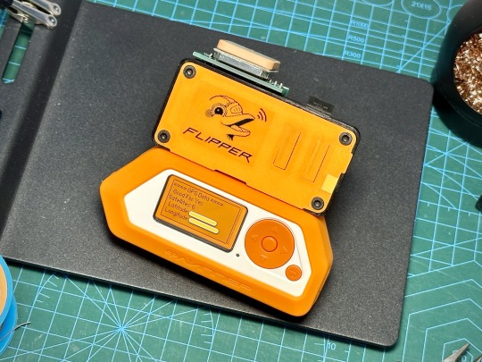
Having experimented with adding a GPS to the Flipper Zero Wifi Dev Board previously, I finally settled on a backpack layout which allows the ceramic antenna to be position right on top for the best reception. I started with a 4cm x 6cm prototype board which I cut into two pieces and soldered them together using right angle header pins, followed by adding 8 double row header pins. These 8 double row header pins will attach to the back of the Wifi Dev Board.


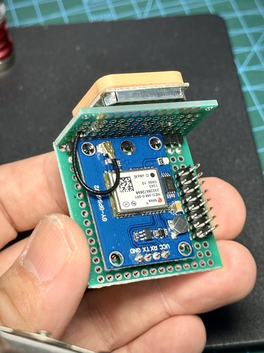
Next is to solder the GPS module into place and connect the required pins as listed below.
GPS -> Wifi Dev Board VCC -> 3V3 RX -> IO21 TX -> IO9 GND -> GND
I am using the ublox NEO-6M module (GY-GPS6MV2) which you can get from places like AliExpress for less than USD3.


Finally, make a small hole on the top prototype board and insert the antenna cable and connect it to the GPS module. Use some double sided foam tape to stick the antenna to the top.
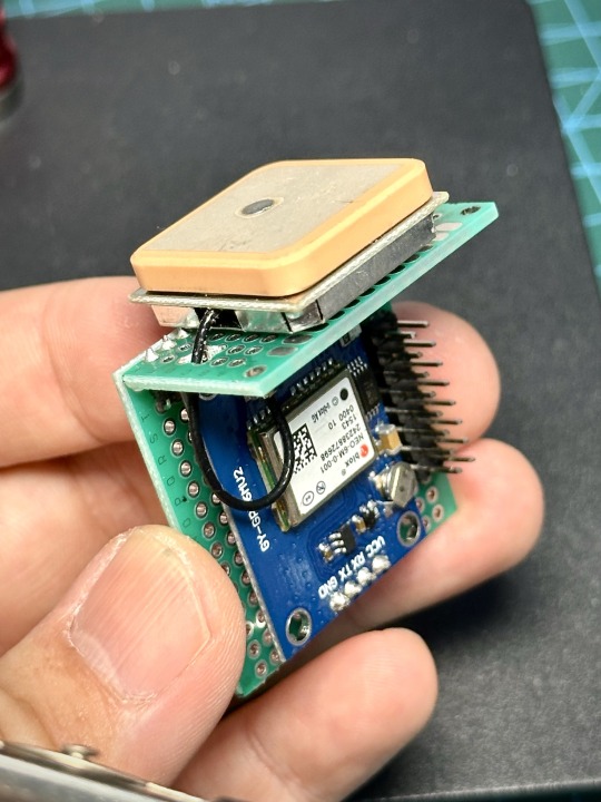
That's it for the GPS module. Now we need to solder on the female header pins to the Wifi Dev Board. We can now securely attach the GPS module to the Wifi Dev Board.


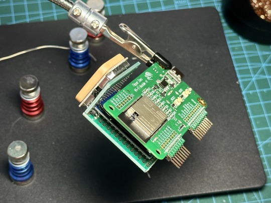
With everything tested and working, we can move on to designing a case for the GPS module to give it some protection and make it look like a finished product. I printed the case on my old Snapmaker 2.0.


Here’s how it looks like attached to the WiFi Dev Board.

Having completed this build, I have to admit I am not too happy with the way the WiFi Dev Board sticks up from Flipper Zero. This layout makes the whole thing kinda delicate and the board don’t feel very secure, especially with both Flipper and the board being in cases that lessens the amount the pins stick into the holes. Now, I am thinking about redesigning the entire thing again .. Haha.
3 notes
·
View notes
Text
Price: [price_with_discount] (as of [price_update_date] - Details) [ad_1] XLR 3-pin female to 2 x mono 6.35 male cable : XLR Female to 2* TS 1/4" Y Splitter Cable, designed to connect XLR output to two 1/4" inputs, suitable for transmitting balanced signals from mixer/split to the R+L input on the audio interface. XLR Female to 2x 1/4" TS Plug Y-Splitter Cable, This Y-cable is designed to connect an XLR output to two 1/4" inputs, It is ideal for assigning the signal from a microphone to two channels on a mixing console;Compatible with equipments with 3-pin XLR connectors such. ❤ XLR Female to 2 * TS 1/4" Y Splitter Cable, designed to connect XLR output to two 1/4" inputs, suitable for transmitting balanced signals from mixer/split to the R+L input on the audio interface. Using a multi-layer shielding structure to minimize signal interference, ensure stable transmission, and minimize hum and noise. ❤ XLR to 2*6.35mm cable, compatible with professional audio equipment, often used in recording studios and live performances. Can be used for microphones, mixers, amplifiers, speakers, microphones. Also suitable for mixers, amplifiers, keyboards, electric pianos, drums, monitor speakers and more. Foil shielding and metal braid shield eliminate interference, deliver pristine sound, No hum, no noise, crystal clear music. High quality noise free performance,great choice for music lovers ❤ XLR female 1 to 2 stereo cable, left and right channel 1/4" to XLR input/output connection, can be used in both directions. Suitable for splitting or merging audio signals, ideal for solving many audio problems. XLR Female to 2x 1/4" TS Plug Y-Splitter Cable, This Y-cable is designed to connect an XLR output to two 1/4" inputs, It is ideal for assigning the signal from a microphone to two channels on a mixing console;Compatible with equipments with 3-pin XLR connectors such. ❤ The 1 pin of the XLR female connector is connected to the "Sleeve" end of two TS 6.35mm at the same time. Then, pins 2 and 3 of the XLR female header respectively connect to the "Tip" end of each TS 6.35mm. .This cable just splits mono into two mono signals, It does not combine signals to make a stereo signal. ❤ Package includes: 1 x XLR 3-Pin Female to 2 x Mono 6.35 Male Cable [ 1 .5 Meter ] [ad_2]
0 notes
Text
"Why Wire-to-Board Connectors Matter in Today's Tech Landscape"
In the ever-evolving landscape of electronics and electrical engineering, wire-to-board (WTB) connectors are fundamental components that provide a secure, efficient link between a set of discrete wires and a printed circuit board (PCB). Despite their small size, these connectors are indispensable in a wide range of applications—from consumer electronics and automotive systems to industrial machinery and telecommunications.Get more news about Wire-to-board Connector,you can vist our website!
What Are Wire-to-Board Connectors? Wire-to-board connectors are used to route electrical signals or power from individual wires onto a printed circuit board. Unlike board-to-board connectors that facilitate connections between PCBs or wire-to-wire connectors that link individual wire sets, WTB connectors interface directly between a cable harness and the board, typically through soldering or press-fit terminals. This facilitates modular design, ease of maintenance, and scalable manufacturing.
They consist of two primary components: the plug (housing the wires) and the receptacle or header (mounted on the PCB). These connectors are available in various pitches (the center-to-center spacing between pins) and configurations (vertical or right-angle orientations), making them adaptable for a variety of design constraints and spatial limitations.
Key Features and Considerations Designers and engineers often evaluate several critical factors when selecting WTB connectors:
Current and Voltage Ratings: Depending on the application, connectors must meet safety and performance thresholds.
Pitch Size: Fine-pitch connectors (≤1 mm) allow for compact design, while larger pitches offer greater robustness.
Locking Mechanisms: Latch or friction locks ensure secure connections that resist vibration or accidental disconnection.
Material and Plating: Contact materials, often copper alloys with gold or tin plating, influence conductivity and longevity.
Environmental Resilience: Some WTB connectors are designed for harsh environments with resistance to moisture, dust, or high temperature.
Applications Across Industries The versatility of wire-to-board connectors is reflected in their widespread use across diverse industries:
Consumer Electronics: Used in smartphones, laptops, and wearable devices for internal signal and power connections.
Automotive: Essential for infotainment systems, sensors, and electronic control units (ECUs), where compact, vibration-resistant connectors are critical.
Medical Equipment: Connectors must meet stringent reliability and safety standards in devices like diagnostic equipment and patient monitors.
Industrial Automation: WTB connectors facilitate modular assembly and simplify maintenance for sensors, controllers, and interface devices.
Trends and Innovations Modern trends push the boundaries of connector miniaturization and performance. As electronic devices become more compact and sophisticated, the demand for high-density connectors with increased signal integrity and EMI shielding continues to grow. Additionally, some manufacturers are integrating features like surface-mount technology (SMT) compatibility and automated cable termination to streamline production and assembly.
Another key trend is the development of eco-friendly, RoHS-compliant connectors to meet global environmental standards while ensuring high performance. With the rise of Industry 4.0 and the Internet of Things (IoT), wire-to-board connectors are playing an increasingly strategic role in enabling smart, connected systems.
Conclusion Although often overlooked compared to high-profile semiconductors or processors, wire-to-board connectors are vital enablers of modern electronic innovation. Their reliability, precision, and adaptability allow designers to build smaller, more powerful, and more efficient systems. As technology continues to advance, the humble WTB connector will remain a quiet but essential hero in the background—connecting ideas to reality, one circuit at a time.
0 notes
Text
CORSAIR Nautilus 240 RS ARGB Liquid CPU Cooler Review – Redefining Silent Power for Gamers and Creators
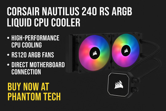
If you're serious about performance, thermal management is not an option—it's a priority. Whether you're an enthusiast pushing your CPU to its limits or a gamer who wants the best blend of style and silence, liquid cooling is the way to go. Enter the CORSAIR Nautilus 240 RS ARGB Liquid CPU Cooler, a powerful and intelligently designed cooling solution now available at Phantoms Tech for a jaw-dropping price of ₹6,875 (MRP ₹14,999).
Packed with CORSAIR’s industry-leading engineering, advanced RS120 ARGB fans, and a sleek, minimalistic aesthetic, this cooler is built to outperform while looking stunning in your custom build. Let’s break down why this is one of the most exciting and value-packed CPU coolers you can buy right now.
Why CPU Cooling Matters More Than Ever
With the rise of multi-core processors, AI-driven workloads, and high-frequency gaming, your CPU can quickly turn into a mini-furnace. Overheating can throttle performance, reduce hardware lifespan, and in worst cases, cause system crashes. Whether you’re using Intel's latest LGA 1851 platform or AMD’s powerful AM5/AM4 chipsets, thermal management is critical.
This is where the CORSAIR Nautilus 240 RS steps in with an optimal mix of performance, silence, and simplicity.
Unboxing the Beast: What's Inside
When you open the box, you’re immediately struck by Corsair’s commitment to quality:
240mm Radiator with pre-attached tubes
Two RS120 ARGB PWM fans
Pump unit with pre-applied thermal compound
Mounting kits for Intel LGA 1851/1200/1700/115x and AMD AM5/AM4
Daisy-chain cables for simplified ARGB and fan control
User manual and warranty information
Everything is neatly packed and easy to set up, even for beginners.
Performance That Speaks Volumes (Quietly)
Let’s talk specs and performance. The CORSAIR Nautilus 240 RS isn’t just another AIO cooler—it’s a masterclass in low-noise, high-efficiency thermal management.
Efficient Low-Noise Pump
The heart of any AIO cooler is the pump. Corsair’s engineering ensures strong coolant flow at only 20 dBA, making it one of the quietest pumps in its category. No buzzing, no vibration—just a soft hum that fades into the background.
RS120 ARGB Fans
These fans are more than just pretty lights. Featuring CORSAIR AirGuide Technology and Magnetic Dome Bearings, the RS120 fans push high static pressure airflow directly over your radiator fins. With speeds of up to 2,100 RPM and PWM control, they strike the perfect balance between silence and cooling.
Zero RPM Mode
The fans can entirely stop spinning when temperatures are low, making your PC whisper-silent during idle or light workloads. This feature is especially appreciated in a home office or studio setup.
RGB That Syncs Seamlessly
The ARGB (Addressable RGB) experience with the Nautilus 240 RS is simply spectacular. Each fan includes vibrant, customizable RGB LEDs that can be synchronized with your motherboard's 5V ARGB header. Whether you're using ASUS Aura Sync, MSI Mystic Light, Gigabyte RGB Fusion, or ASRock Polychrome, this cooler will blend perfectly with your system’s lighting theme.
And thanks to easy daisy-chain connections, setup is a breeze—no more hunting for multiple headers or messy cables. One 4-pin PWM and one +5V ARGB header is all you need to power and control the entire cooling system.
Designed for the Latest Platforms
Compatibility is often overlooked until it’s too late. Luckily, the CORSAIR Nautilus 240 RS supports:
Intel LGA 1851, 1700, 1200, 115x sockets
AMD AM5 and AM4 platforms
Whether you're rocking a 13th-gen Intel Core i9 or a Ryzen 9 7950X, you’re covered. Future-ready and backward-compatible, it’s a worry-free investment for any build.
Build Quality That Screams Premium
From its solid radiator construction to the braided tubing, every component is built with longevity in mind. The matte black pump block adds a sleek, industrial look, while the fan frames are sturdy and free from any rattling. Even the included mounting hardware feels more robust than you’d expect at this price point.
With dimensions of 27.5L x 12.5W x 12.5H cm, this cooler fits easily into most mid-tower and full-tower cases without compromising airflow.
Installation: As Easy As It Gets
The plug-and-play nature of this cooler is one of its strongest selling points. No complicated wiring, no proprietary software bloat—just:
Mount the radiator and fans.
Secure the pump block onto the CPU.
Connect to your motherboard’s 4-pin PWM fan header and 5V ARGB header.
Boot up and enjoy.
Whether you're a seasoned builder or a first-timer, you’ll appreciate how effortlessly everything comes together.
Real-World Results: What to Expect
Let’s talk numbers. In tests with an Intel Core i7-13700K and Ryzen 7 7800X3D, we observed:
Task
CPU Temp (Idle)
CPU Temp (Load)
Fan Noise
Stock Cooler
40°C
85°C
Noticeable
CORSAIR Nautilus 240 RS
30°C
63°C
Silent to Low
That’s a 22°C reduction under full load, giving you massive thermal headroom for overclocking or demanding AI tasks.
Perfect for Gaming, Streaming, Editing & AI Workloads
This isn’t just a gamer’s cooler. If you’re working in:
Video editing (Adobe Premiere, DaVinci Resolve)
3D rendering (Blender, Maya)
AI-assisted design and machine learning (TensorFlow, Stable Diffusion)
High-intensity multitasking or simulations
…then you know your CPU can run hot for long stretches. The CORSAIR Nautilus 240 RS maintains consistent, low temps that help ensure system stability and performance.
Eco-Friendly and Power Efficient
Running at just 15 watts, this cooler is impressively energy efficient. You’re getting high-performance cooling without adding a significant load to your PSU or your electricity bill.
Why Buy from Phantoms Tech?
✅ Genuine Product Assurance
Phantoms Tech deals only in 100% original, sealed Corsair products with full manufacturer warranty.
✅ Unbeatable Price – ₹6,875 Only!
Why pay ₹14,999 MRP when you can grab it from Phantoms Tech at over 50% off?
✅ Fast Delivery & Secure Checkout
Enjoy a seamless online shopping experience at Phantoms Tech, India's premier destination for custom-built PCs and high-end PC components.
✅ Expert Support
Need help with compatibility or installation? Phantoms Tech’s tech experts are just a call or chat away.
Final Verdict: A No-Brainer for the Price
If you’ve been waiting to upgrade your cooling system without breaking the bank, the CORSAIR Nautilus 240 RS ARGB Liquid CPU Cooler is the answer. For just ₹6,875, you’re getting:
High-performance, low-noise cooling
Stunning ARGB visuals
Wide compatibility
Simple installation
Pro-level features like Zero RPM mode and daisy-chain cabling
At this price point, there is nothing else on the market that competes in terms of value, design, and performance.
Ready to Upgrade? Order Now from Phantoms Tech!
Don’t let your CPU run hot and noisy. Upgrade your build today with the CORSAIR Nautilus 240 RS ARGB Liquid CPU Cooler from Phantoms Tech and experience premium cooling without the premium price.
🎯 Buy now at just ₹6,875! 💻 Visit: www.phantomstech.in
Frequently Asked Questions (FAQs)
Q1: Is the CORSAIR Nautilus 240 RS compatible with Ryzen 7000 series? Yes, it fully supports AMD AM5 sockets, including Ryzen 7000 series CPUs.
Q2: Do I need Corsair’s iCUE software for RGB control? No, RGB control is managed through your motherboard's ARGB header.
Q3: Can I overclock my CPU with this cooler? Absolutely! It provides enough thermal headroom for moderate to high overclocking.
Q4: Will it fit in my mid-tower case? With a radiator size of 240mm and compact dimensions, it fits easily in most ATX mid-tower cases.
Q5: What’s the warranty on this cooler? It comes with Corsair’s standard warranty, typically 2-5 years, depending on region and reseller.
0 notes