#SCR Transistor
Explore tagged Tumblr posts
Visit Tumblr Blog
Explore Tumblr blogs with no restrictions, modern design and the best experience.
Last Seen Tumblr Blogs


Fun Fact
Average visit duration of Tumblr.com is 10 mins and 25 secs.
Text
Powerex KSB13060: The Powerhouse of Silicon-Controlled Rectifiers (SCRs)
Buy KSB13060 and other power semiconductors for as low as $1 at https://www.uscomponent.com/buy/Powerex/KSB13060.
In the dynamic field of power electronics, ensuring robust and efficient control of high-power applications is critical. Powerex introduces the KSB13060, a high-performance Silicon Controlled Rectifier (SCR) designed to meet the rigorous demands of industrial and commercial power control systems. Whether you are managing motor drives, power supplies, or industrial heaters, the KSB13060 delivers unmatched performance, reliability, and efficiency.
Exceptional Performance
The Powerex KSB13060 is engineered to deliver outstanding performance across a broad range of applications. With a voltage rating of 600V and a current rating of 130A, this SCR is capable of handling significant power loads with ease. Its high surge current capability ensures reliable operation even under extreme conditions, making it an ideal choice for applications requiring high power and durability.
Robust Construction
Reliability and durability are at the core of the Powerex KSB13060. Constructed with high-quality materials and advanced manufacturing processes, this SCR is designed to withstand harsh environments and demanding operating conditions. Its rugged design ensures long-term stability and performance, reducing maintenance costs and downtime.
Versatile Applications
The versatility of the KSB13060 makes it suitable for a wide range of applications. In motor control systems, it provides precise and reliable power control, ensuring smooth operation and extended motor life. For power supplies and rectifiers, the KSB13060 ensures efficient and stable power conversion. It is also an excellent choice for industrial heating applications, where precise temperature control is essential for optimal performance.
Easy Integration
Powerex understands the importance of seamless integration in your power control systems. The KSB13060 is designed for easy installation and compatibility with a variety of control circuits. Its standard package size and configuration simplify the upgrade process, allowing for quick and hassle-free implementation in existing systems. This ease of integration helps minimize downtime and ensures a swift return on investment.
Superior Control
The KSB13060 offers superior control capabilities, with fast switching speeds and low switching losses. Its excellent thermal management ensures consistent performance, even under heavy load conditions. This high level of control enhances the efficiency and reliability of your power systems, contributing to improved overall performance and reduced energy consumption.
Environmentally Conscious
In an era where energy efficiency and environmental responsibility are paramount, the KSB13060 stands out as an eco-friendly solution. By enhancing the efficiency of power control systems and reducing energy losses, it helps lower your carbon footprint and supports sustainable operations. Integrating the KSB13060 into your systems is a step towards greener and more responsible technology solutions.
Conclusion
The Powerex KSB13060 SCR is more than just a semiconductor device; it's a cornerstone of advanced power control systems. With its exceptional performance, robust construction, versatile applications, easy integration, superior control, and environmental benefits, the KSB13060 sets a new benchmark in the industry.
Upgrade your power control solutions with the Powerex KSB13060 and experience the future of high-power applications. For more information and to see how this powerful SCR can enhance your operations, visit our website or contact our sales team. Embrace the power of innovation with Powerex.
#SCR#Semiconductor#Transistor#Silicon Controlled Rectifiers#Powerex#Electronic Components Distributor#SCR Electronics#SCR Silicon Controlled Rectifier#Power SCR#Powerex SCR#SCR Transistor#High Voltage SCR#Powerex Distributor
0 notes
Text
Silent Powerhouses: How igbt rectifiers Are Redefining Industrial Energy Conversion
Picture a bustling manufacturing floor at dawn. Conveyor belts glide, robotic arms pivot with precision, and high-power motors hum in perfect synchrony. All of this choreographed action relies on stable direct current—even though the utility grid delivers alternating current. Converting AC to DC might sound mundane, yet it’s the unglamorous heartbeat of virtually every modern factory, data center, and electric-rail system. Tucked inside control cabinets and power bays, igbt rectifiers are the silent powerhouses making this conversion cleaner, smarter, and dramatically more efficient.
From Diodes to Digital Brains
For decades, silicon diodes and thyristors dominated rectification. They were sturdy, inexpensive, and—let’s be honest—fairly dumb. They could only switch on and off in crude, bulk fashion, producing DC that was rife with voltage ripple and harmonic distortion. That was acceptable in an analog world, but today’s precision-driven operations need better. Enter the Insulated Gate Bipolar Transistor (IGBT): a semiconductor that marries the high-current capability of a bipolar transistor with the fast switching of a MOSFET.
When engineers embed IGBTs in rectifier topologies, the result is a new class of high-frequency converters capable of pulse-width modulation (PWM), soft-start functions, and active power-factor correction. Suddenly, rectification isn’t just about flipping waveform polarity—it’s about sculpting perfect current for sensitive loads, saving megawatts in the process.
A Day in the Life: Humanizing High Tech
Let’s walk in the shoes of Ananya, maintenance lead at a sprawling metro-rail depot in Bengaluru. She remembers the era when traction substations ran on mercury-arc or SCR rectifiers. “It was like taming a dragon,” she jokes. Voltage spikes chewed through bearings, transformers overheated, and harmonics crept back onto the grid. Then came the retrofit: a modular cabinet stuffed with igbt rectifiers. Overnight, the depot saw a 6 % drop in energy losses and, more surprisingly, quieter lines. “Passengers didn’t notice the upgrade,” Ananya says, “but my team sleeps better knowing the system’s self-diagnostics flag issues before they escalate.”
That’s the hidden human upside—less emergency call-outs, more predictive maintenance, and a work culture that shifts from crisis mode to optimization mode.
Under the Hood: Why IGBT Architecture Shines
High-Frequency Switching IGBTs can switch tens of kilohertz, shrinking bulky transformers and filters. Smaller magnetics mean lighter enclosures and better thermal management.
Low Conduction Losses Compared to MOSFETs at high voltage, IGBTs maintain lower on-state resistance, translating into cooler operation and longer component life.
Built-In Protection Advanced gate-driver ICs monitor temperature, current, and voltage in real time, shutting down the device within microseconds if thresholds are breached.
Bidirectional Capability Paired with appropriate circuitry, they enable regenerative braking in electric locomotives, feeding energy back to the grid instead of dumping it as heat.
Sustainability by Design
Energy efficiency isn’t just a line on a spec sheet—it’s a planetary necessity. Traditional 12-pulse SCR rectifiers often hover near 90 % efficiency under ideal loads. Modern PWM-controlled igbt rectifiers push beyond 97 %, slicing gigawatt-hours off cumulative utility bills over their service life. Multiply that by thousands of installations and you have a tangible dent in global CO₂ emissions.
Moreover, precise DC output means motors run cooler, electrolytic capacitors last longer, and upstream generators experience smoother load profiles. Less wear equals fewer raw materials mined, shipped, and processed for replacements—a virtuous cycle of resource conservation.
Beyond the Factory: Emerging Frontiers
Data Centers – Hyperscale operators love IGBT rectifiers for redundant, hot-swappable power shelves that squeeze more watts per rack while meeting stringent harmonic limits (IEEE 519).
Electrolysis for Green Hydrogen – Stable, low-ripple DC is crucial for membrane longevity. As electrolyzer farms scale into the gigawatt realm, PWM rectifiers slash idle losses and enable dynamic ramp-up tied to renewable generation.
EV Hyper-Chargers – Ultra-fast DC stations (350 kW and higher) rely on modular IGBT blocks to convert grid AC into tightly regulated DC that won’t fry delicate vehicle battery chemistries.
Challenges on the Road Ahead
No technology is perfect. IGBT modules are sensitive to over-voltage transients and require sophisticated snubber networks. Their thermal cycling limits call for meticulous heatsink design and, in harsh climates, liquid cooling. Meanwhile, wide-bandgap semiconductors—silicon carbide (SiC) and gallium nitride (GaN)—are nipping at IGBT heels, promising even faster switching and lower losses.
Yet cost remains king. For high-power (≥ 1 MW) applications, mature supply chains and proven robustness keep igbt rectifiers solidly in the lead. Hybrid topologies that mix SiC diodes with IGBT switches already deliver incremental gains without breaking budgets.
Skills and Workforce Implications
Technicians who once wielded soldering irons on analog boards now brandish oscilloscopes with gigahertz bandwidth to capture nanosecond edge transitions. Training programs are evolving: power-electronics courses in Indian ITIs and polytechnics now include gate-drive design, thermal simulation, and module-level repair practices.
For young engineers, this field offers a blend of hands-on tinkering and digital analytics. Predictive-maintenance dashboards stream real-time data—junction temperatures, switching losses, harmonic spectra—turning power rooms into high-tech command centers.
Final Reflections: Small Silicon, Massive Impact
It’s easy to overlook the humble converter tucked behind a metal door. But in the grand choreography of electrification, igbt rectifiers are the quiet conductors, synchronizing renewable surges, feeding smart grids, and keeping industry humming. They exemplify how incremental innovations—faster switches, smarter firmware, better cooling—compound into game-changing efficiency.
Next time you glide on an electric train, boot up a cloud server, or see a wind farm blinking on the horizon, remember: somewhere underneath, tiny gates are opening and closing thousands of times a second, silently shaping the clean-energy era. And that is technology worth celebrating, even if it never seeks the spotlight.
0 notes
Text
Price: [price_with_discount] (as of [price_update_date] - Details) [ad_1] Electronics Fundamentals and Applications is authored by eminent authors Prof. D. Chattopadhyay and Prof. P.C. Rakshit and is published by one of the leading publishers, NEW AGE International Publishers. This latest Colour Edition of the book is intended for the undergraduate and postgraduate students of Engineering and Physics. The book is recommended by various IITs, NITs and other top Engineering Colleges and Universities. This is one of our best selling books on Electronics. This book is meant for the students pursuing a beginners' course in electronics. Current syllabi of basic electronics included in physics (Honours/Major) curricula of different universities and those offered in various engineering and technical institutions have been consulted in preparing the material contained herein. In 23 chapters, the book deals with the formation of energy bands in solids; electron emission from solid surfaces; properties of semiconductors; metal-semiconductor contacts; pn junction diodes; rectifiers; voltage multipliers; clipping and clamping circuits; bipolar junction transistors; basic voltage and power amplifiers; feedback in amplifiers; regulated power supplies; sinusoidal oscillators; multivibrators; modulation and demodulation; field-effect transistors; ICs; OP AMPs; active filters; special semiconductor devices such as phototransistor, SCR, triac, diac, UJT, impatt diode, gunn diode, PIN diode, IGBT, etc.; digital circuits and systems; VLSI technology and circuits; CRO; communication systems; television; radar; lasers; fibre optics and holography. Software packages for circuit simulation, namely, spice and Pspice; miscellaneous problems; the re and the hybrid models for BJT; and expressions for the potential barrier, electric field, and depletion - region width of a step-graded p-n junction have been included in Appendices. Fundamental principles and applications are discussed herein with explanatory diagrams in a clear and concise way. Physical aspects are emphasized; and mathematical details are given wherever necessary. Many of the problems, review questions and objective-type questions included in the book are taken from recent examination papers. Publisher : New Age International Private Limited; Seventeenth edition (24 August 2022); New Age International Private Limited Language : English Paperback : 772 pages ISBN-10 : 9393159858 ISBN-13 : 978-9393159854 Reading age : 18 years and up Item Weight : 995 g Dimensions : 23 x 15.3 x 2.4 cm Country of Origin : India Net Quantity
: 1 Count Importer : NEW AGE International, 7/30A, Near LIC Flats, Daryaganj, ND110002 Packer : NEW AGE International, 7/30A, Near LIC Flats, Daryaganj, ND110002 Generic Name : Book [ad_2]
0 notes
Text
The global Thyristor Market is projected to grow from USD 5,764 million in 2024 to USD 8,196.98 million by 2032, reflecting a compound annual growth rate (CAGR) of 4.5% over the forecast period.The thyristor, a key component in power electronics, has emerged as a cornerstone in applications requiring high voltage and current control. Its ability to handle significant power loads while ensuring efficiency has made it indispensable in industries such as automotive, energy, consumer electronics, and industrial manufacturing. The global thyristor market has seen robust growth over the past few years, driven by advancements in renewable energy systems, industrial automation, and the proliferation of electric vehicles (EVs).
Browse the full report https://www.credenceresearch.com/report/thyristor-market
Market Overview
Thyristors are semiconductor devices that act as electronic switches, controlling the flow of electricity in high-power applications. Key types of thyristors include:
SCR (Silicon Controlled Rectifier): Used in AC and DC systems.
GTO (Gate Turn-Off Thyristor): Widely employed in industrial and traction applications.
IGCT (Integrated Gate Commutated Thyristor): A high-performance option for power systems.
The global thyristor market was valued at approximately $4 billion in 2023 and is projected to grow at a compound annual growth rate (CAGR) of 5–7% during 2024–2030. This growth is fueled by the increasing demand for efficient power control systems, the adoption of renewable energy, and the rise of electric mobility.
Key Growth Drivers
Proliferation of Renewable Energy Renewable energy sources like wind and solar heavily rely on thyristors for power conversion and grid integration. These devices ensure efficient energy transmission by stabilizing voltage fluctuations, making them critical to expanding renewable energy infrastructure.
Rise of Electric Vehicles (EVs) With the global shift towards sustainability, the demand for EVs is skyrocketing. Thyristors are integral in managing power within EV charging stations and motor control systems, contributing to their increased adoption in the automotive sector.
Industrial Automation The growing trend of automation in manufacturing and industrial processes necessitates precise control over high-power systems, a role thyristors are well-suited for. This demand is particularly evident in sectors like steel manufacturing, railways, and heavy machinery.
Infrastructure Development in Emerging Markets The rapid urbanization and industrialization of emerging economies like India and China are driving investments in power distribution and infrastructure projects. Thyristors are essential in these large-scale energy management systems.
Challenges
Despite its growth prospects, the thyristor market faces several challenges:
Competition from Alternative Technologies Advances in Insulated Gate Bipolar Transistors (IGBTs) and MOSFETs pose competition to thyristors in certain applications, particularly in lower power ranges.
High Initial Costs Implementing thyristor-based systems can involve significant upfront investment, which may deter adoption, especially in cost-sensitive markets.
Complex Manufacturing Processes Thyristors require precise fabrication techniques, leading to higher production costs and limiting market entry for new players.
Future Prospects
The future of the thyristor market is intertwined with the global push for sustainability. Key trends include:
Integration with Smart Grids: Thyristors will play a vital role in creating intelligent energy systems capable of balancing supply and demand efficiently.
Adoption of Advanced Materials: Innovations in silicon carbide (SiC) and gallium nitride (GaN) materials are expected to enhance thyristor performance, opening new possibilities for applications in harsh environments.
AI and IoT Integration: The integration of AI and IoT technologies in power systems will require high-performance thyristors for seamless operation.
Key Player Analysis:
STMicroelectronics
Vishay Intertechnology
Schneider Electric
TSMC
Sensata Technologies
ABB Ltd
Infineon Technologies AG
ON Semiconductor
Siemens AG
Honeywell International Inc.
Segmentations:
By Power Rating
500 MW
500 MW-1000 MW
1000 MW
By End Use
Consumer Electronics
Telecommunication & Networking
Industrial
Automotive
Aerospace & Defence
Others
By Geography
North America
U.S.
Canada
Mexico
Europe
Germany
France
U.K.
Italy
Spain
Rest of Europe
Asia Pacific
China
Japan
India
South Korea
South-east Asia
Rest of Asia Pacific
Latin America
Brazil
Argentina
Rest of Latin America
Middle East & Africa
GCC Countries
South Africa
Rest of the Middle East and Africa
Browse the full report https://www.credenceresearch.com/report/thyristor-market
Contact:
Credence Research
Please contact us at +91 6232 49 3207
Email: [email protected]
Website: www.credenceresearch.com
0 notes
Text
Power electronics involves the use of solid-state electronics to control and convert electric power. This course covers the application of power electronic converters in modifying electrical energy. Students learn about semiconductor-switching devices like power diodes, SCR, and transistors for power conversion. The course also covers electrical machines, basic and advanced electronics concepts, microcontroller applications in the power industry, and electronic instrumentation techniques for high-power systems. Practical training includes hands-on experience in high-frequency DC converters, PCB designing and fabrication, and power component mounting. Students work on projects to apply their theoretical knowledge before completing the course.
#nttf#diploma courses#diploma course nttf#nettur technical#diploma in mechatronics#bangalore nettur#diploma in mechatronics engineering#diploma in electronics#diploma in tool engineering#campus placement
0 notes
Text
Semiconductor Parts in the Aircraft Industry: Enhancing Safety and Efficiency
In the fast-paced world of aviation, where precision, reliability, and safety are paramount, the role of semiconductor components cannot be overstated. These tiny yet powerful devices form the backbone of modern aircraft systems, enabling critical functions that ensure smooth operations from takeoff to landing. Let’s explore some key semiconductor parts and their contributions to the aerospace industry.
Diodes: Directing Current Flow with Precision
Diodes are fundamental semiconductor components in aircraft systems. They primarily serve to control the direction of electric current, ensuring that electricity flows in only one direction. In aviation, diodes are used in various applications such as power supplies, switching circuits, and voltage regulation. They play a crucial role in protecting sensitive electronic equipment from reverse voltage spikes and ensuring stable operation of essential systems.
Triacs: Controlling AC Power
Triacs are semiconductor devices that enable the precise control of AC (alternating current) power. They are extensively used in aircraft for applications such as dimming lights, controlling heating elements, and managing motor speed. Triacs allow for efficient and reliable adjustment of power levels, contributing to energy savings and operational flexibility in onboard systems.
Transistors: Switching and Amplification
Transistors are perhaps the most versatile semiconductor devices found in aircraft electronics. They serve dual roles as switches and amplifiers, crucial for controlling signals and power in avionics systems. Transistors enable efficient switching of digital signals, amplification of weak signals from sensors, and modulation of radio frequencies in communication systems. Their reliability and performance under varying environmental conditions make them indispensable in aerospace applications.
Bridge Rectifiers: Converting AC to DC
Bridge rectifiers are semiconductor assemblies used to convert alternating current (AC) into direct current (DC). In aircraft, where numerous systems and equipment rely on DC power, bridge rectifiers play a critical role in converting power from generators and other AC sources into a usable form. They ensure a steady and reliable supply of DC voltage for avionics, navigation instruments, communication devices, and other essential onboard systems.
SCRs (Silicon-Controlled Rectifiers): Ensuring Power Regulation
SCRs are semiconductor devices used for precise control of large electrical currents. They excel in applications requiring high current regulation and are commonly found in aircraft power management systems. SCRs ensure efficient power distribution, voltage regulation, and protection against overcurrent conditions. Their robust design and ability to handle high-power loads make them essential for maintaining the reliability and safety of critical aircraft systems.
Challenges and Innovations in Semiconductor Technology
The aerospace industry poses unique challenges for semiconductor technology. Aircraft operate in extreme environmental conditions, including wide temperature ranges, high altitude, and electromagnetic interference. Semiconductor manufacturers continually innovate to develop components that meet stringent aerospace standards for reliability, durability, and performance under such demanding conditions.
Advanced materials and manufacturing techniques are key to producing semiconductor parts capable of withstanding the rigors of flight. Specialized coatings, ruggedized designs, and enhanced thermal management techniques ensure that semiconductor devices maintain optimal performance throughout their operational lifespan.
Future Directions and Beyond
Looking forward, semiconductor technology will continue to drive innovation in the aerospace industry. Advancements in materials science, miniaturization, and integration will enable more compact and energy-efficient aircraft systems. The ongoing development of smart sensors, artificial intelligence, and connectivity solutions will further enhance aircraft performance, safety, and passenger comfort.
In conclusion, semiconductor components are integral to the evolution of aviation technology, enabling aircraft to operate more efficiently, safely, and reliably. As aerospace engineering continues to push boundaries, semiconductor innovation will play a central role in shaping the future of air travel, ensuring that aircraft remain at the forefront of technological advancement in the 21st century and beyond.
#semiconductors#aircraft parts#aviation industry#aerospace#aviation parts#aerospace industry#industrial parts supplier
1 note
·
View note
Text
Tentang bimbingan tugas akhir/seminar tahun ini.
Tulisan ini saya sampaikan hanya untuk mahasiswa saya, jika bisa diambil manfaatnya oleh yang lain saya akan lebih bersyukur.
Berdasarkan pengalaman pembimbingan dan pengujian, maka untuk tahun ini ada beberapa pengaturan jika seandainya ada mahasiswa berniat mengambil saya sebagai calon pembimbing tugas akhir/skripsinya.
Memahami dasar-dasar dan syntax pemrograman Arduino. Sekalipun proyek akhir (TA/skripsi) yang akan diambil tidak menggunakan mikrokontoler apa pun, calon bimbingan tetap perlu memahami dasar pemrograman sebagai latihan logika. Kecuali untuk mahasiswa D3, maka pemahaman akan diperiksa saat menyerahkan bakal proposal. Hal ini karena berdasarkan jadwal, mahasiswa D3 belum mendapatkan kuliah mikroprosesor. Sehingga perlu belajar singkat secar otodidak.
Menguasai dengan cukup baik penggunaan LTspice. Umumnya TA/skripsi rancang bangun masih mempergunakan komponen, karena itu kemampuan simulasi masih diperlukan. Selain itu kemampuan untuk mengoperasikan LTspice bisa menjadi indikator awal keseriusan belajar.
Punya pemahaman dasar mengenai bidang yang akan dibahas. Sekalipun belum mengerjakan tugas akhir/skripsi, mahasiswa sudah harus cukup banyak membaca dan menyimak audiovisual mengenai topik yang akan diajukan. Ini untuk menghindari mahasiswa yang asal-asalan mengajukan topik/judul dan sama sekali tidak mengerti dasar-dasar topik/judul yang akan dibahas.
Bisa menyelesaikan proposal tugas akhir/skripsi sebelum disetujui untuk dibimbing. Berbeda dari tahun sebelumnya, tahun ini saya hanya akan bersedia sebagai calon pembimbing jika mahasiswa secara resmi sudah menyelesaikan proposalnya.
Nilai ELDA yang cukup baik untuk mahasiswa S1. Khusus untuk mahasiswa S1, karena sudah mengikuti ELDA I dan ELDA II maka nilainya harus cukup baik. Apa pun bidang/topik/judul yang akan diambil, termasuk jika tidak mengambil bahasan dalam bidang ELDA. Karena nilai ELDA adalah salah satu indikator keseriusan mahasiswa yang bersangkutan.
Perlu saya ingatkan bahwa tugas akhir/skripsi adalah pekerjaan mandiri oleh mahasiswa. Tugas dosen pembimbing adalah untuk membantu mengarahkan dan memotivasi. Maka jangan mengambil bidang yang tidak Anda minati dan masalah/judul yang benar-benar belum Anda mengerti bahkan di semester 5 (atau semester 7). Mahasiswa perlu mampu memperikirakan batas kemampuannya sendiri.
Bidang-bidang yang bersedia saya bimbing adalah elektronika daya, embedded system, IoT. Salah satu contoh per bagian komponennya adalah sistem yang menggunakan transistor (BJT & MOSFET), IGBT, diode, SCR, TRIAC, relay, SSR, mikrokontroler (Aduino , ESP8266, ESP32, Raspberry Pico), Raspberry Pi. Penggunaan komponen-komponen tersebut dalam sistem yang dirancang, diserahkan kepada mahasiswa. Permasalahan yang hendak diselesaikan melalui tugas akhir/skripsi diserahkan kepada kreativitas mahasiswa dan kemampuannya.
Bagi yang memang akan mengajukan saya sebagai pembimbing, segera menemui saya di Lab ELDA. Tahun ini, jika pun nanti menjadi pembimbing satu, saya tidak mampu untuk membimbing banyak mahasiswa. Jumlahnya akan jauh di bawah batas maksimal bimbingan. Jika saya tidak menjadi pembimbing satu, biasanya tetap akan menjadi pembimbing yaitu pembimbing dua.
0 notes
Photo
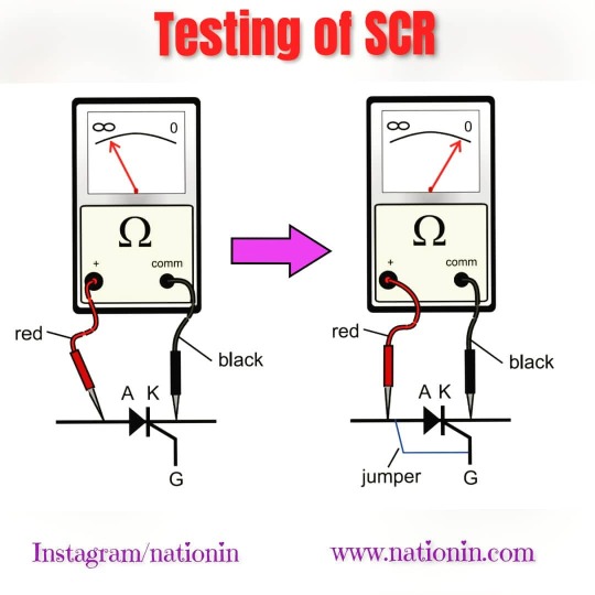
>> Basic testing of Thyristors : SCR ,TRAIC Devices for checking the working condition. >> Power electronics devices testing for Electronics and Electronics engineers ---------------------------------------------------------------------------------- Like👍 ll comments📝 II Share📢 ➡️Keep Supporting🙏 ---------------------------------------------------------------------------------- . . ---------------------------------------------------------------------------------- Follow (@nationin) for more stuff. ---------------------------------------------------------------------------------- . . _____________________________________________________ #testing #powerelectronics #device #scr #multimeter #test #experiment #electronics #electronspark #electronicsolvers #electronicsolution #electronicsengineering #transistor #electrical #electricalengineering #electricalengineers #electronic#arduino #technology #electronicslovers #electricalprojects #sensor #resistor #arduino #wires #project #robot #arduino #electronics #soldering #led #homemade https://www.instagram.com/p/CAExaMyjX-v/?igshid=1clkjx63g93i8
#testing#powerelectronics#device#scr#multimeter#test#experiment#electronics#electronspark#electronicsolvers#electronicsolution#electronicsengineering#transistor#electrical#electricalengineering#electricalengineers#electronic#arduino#technology#electronicslovers#electricalprojects#sensor#resistor#wires#project#robot#soldering#led#homemade
0 notes
Text
Semikron SCR Silicon Controlled Rectifier SKDT115-16
SKDT115-16 is a Silicon Controlled Rectifier (SCR) which is a type of semiconductor device used for controlling high-power electrical circuits by switching them on and off.
The SCR is a three-terminal device with a gate, an anode, and a cathode. When a positive voltage is applied to the gate, it triggers the device, allowing current to flow from the anode to the cathode. The SCR remains in the conducting state until the current flowing through it drops below a certain threshold.
The SKDT115-16 is a high-power SCR with a maximum average forward current rating of 115 amps and a peak repetitive off-state voltage rating of 1600 volts. It is designed to handle high voltage and high current applications, such as motor control, power supplies, and lighting control.
The device is also designed to operate at high temperatures, with a maximum junction temperature of 150°C. This makes it suitable for use in harsh environments where high temperatures are common.
Overall, the SKDT115-16 SCR is a reliable and efficient device for controlling high-power circuits, especially those that require high current and high voltage capabilities. It is commonly used in industrial and commercial applications where reliability and durability are essential.
#Silicon Controlled Rectifier#SCR#SCR Silicon Controlled Rectifier#Controlled Rectifier#SCR Rectifier#SCR Electronics#SCR Transistor#Semikron SCR#Semikron Authorized Distributors#Semikron Distributor#SCR in Power Electronics#Semikron SCR Module#Semikron SKDT115 16#SKDT115 16
0 notes
Text
Rethinking Power: The Real Story Behind IGBT Rectifiers
In a world that increasingly runs on precise, clean, and efficient power, the components managing electrical conversion have quietly evolved into silent heroes. Among them, IGBT rectifiers are not just electronic components—they're the backbone of modern industrial energy management.
But let’s take a step back.
When most people think of rectifiers, their minds go to clunky, heat-generating boxes in power rooms. When they hear “IGBT,” they might vaguely associate it with transistors or semiconductors. But the convergence of IGBT technology with rectification isn't just a minor engineering upgrade—it's a game-changer for how we design everything from EV chargers to steel plants.
Let’s explore this through a fresh lens—not just what IGBT rectifiers are, but why they matter, how they work, and what makes them irreplaceable in high-performance environments.
What Are IGBT Rectifiers, Really?
At the core, rectifiers convert AC (alternating current) to DC (direct current). That’s not new. What is new is the use of Insulated Gate Bipolar Transistors (IGBTs) in that process.
Traditionally, rectification was handled using diodes and thyristors. These worked well but had limitations in speed, control, and efficiency. Enter IGBTs—a hybrid semiconductor device combining the fast switching of a MOSFET with the high voltage handling of a bipolar transistor.
So, IGBT rectifiers are essentially intelligent rectification systems. They provide:
Precision: Regulated, ripple-free DC output.
Efficiency: Higher energy conversion with minimal heat loss.
Control: Real-time adaptability in load conditions.
Compact Design: Less bulky compared to traditional systems.
Think of it as the difference between flipping a light switch and using a dimmer with programmable automation. That’s the leap IGBT tech gives to rectifiers.
Why Now? Why IGBT Rectifiers Matter More Than Ever
We're in the midst of several overlapping revolutions:
The EV boom needs ultra-fast charging with precise voltage/current control.
The renewable energy surge requires smart inverters and converters to store and balance variable power.
Smart factories and Industry 4.0 demand real-time, programmable power systems that talk to the cloud.
IGBT rectifiers are the perfect fit for this new energy landscape.
Let’s say you’re running a manufacturing unit that relies on variable frequency drives (VFDs), robotic arms, and programmable logic controllers (PLCs). Traditional rectifiers might get the job done, but IGBT-based systems will optimize your power usage, reduce downtime, and offer predictive maintenance insights. In short, they don’t just work—they think.
Key Advantages of IGBT Rectifiers: Beyond the Basics
High Power Factor & Low Harmonics Unlike older thyristor-based setups, IGBT rectifiers operate at higher frequencies and reduce total harmonic distortion (THD), making them grid-friendly and compliant with IEEE-519 standards.
Regenerative Capability IGBT-based rectifiers can feed excess energy back into the grid or battery systems, increasing overall energy efficiency—something that’s becoming essential in closed-loop industrial applications.
Compact, Modular Designs With IGBT rectifiers, system integrators can fit more power in less space. That’s critical in EV charging stations, medical equipment, and aerospace technologies.
Real-Time Digital Control Thanks to microcontroller-based architecture, these rectifiers can be monitored, tuned, and diagnosed remotely. Maintenance becomes smarter, faster, and safer.
A Human Story: Real-World Use Case
Let’s humanize this for a second.
Imagine a precision medical device manufacturer in Pune. They need a clean, stable DC supply to power their sensitive electronics—something even a tiny ripple could disrupt. They tried conventional SCR-based rectifiers. But the noise, inefficiency, and lack of control led to frequent failures.
Then they adopted IGBT rectifiers from a specialized vendor. Instantly, they saw:
30% reduction in energy waste.
Improved product consistency.
Remote control over power settings during off-hours.
Now, that’s more than engineering. That’s impact.
Debunking the Myths
“IGBTs are too complex and expensive.”
Yes, the upfront cost is higher than diode or SCR rectifiers. But when you factor in operational savings, power quality, cooling costs, and space savings, IGBT rectifiers often pay for themselves within a year.
“They’re overkill for standard industrial applications.”
That’s changing. What was “high-end” five years ago is now mainstream. The same way LED bulbs replaced CFLs, IGBT rectifiers are replacing their older counterparts, even in medium-scale industries.
“Maintenance is tricky.”
On the contrary, the digital nature of IGBT systems allows predictive diagnostics. That means fewer surprises, fewer shutdowns, and more data-driven control.
Where to Use IGBT Rectifiers
EV Charging Infrastructure
Battery Energy Storage Systems (BESS)
Railway Traction Systems
Industrial Automation and Robotics
Welding & Electrolysis Equipment
Data Centers & High-Performance Computing
Whether you’re a CTO building a next-gen plant or an energy consultant advising on efficiency, IGBT rectifiers deserve a place in your power strategy.
Future-Proofing with IGBT: What’s Next?
We’re entering an age where software-defined power systems will become the norm. IGBT rectifiers, integrated with IoT modules and AI-based controls, will become smarter, more predictive, and even self-healing in the event of fluctuations.
Imagine a grid-tied factory where your rectifier “knows” when to store energy, when to feed back, and when to auto-calibrate based on ambient temperature. This isn’t a pipe dream—it’s already in pilot projects across Europe and East Asia.
And the beauty? It all begins with IGBT rectifiers.
Final Thoughts: More Than a Component
A rectifier might seem like a simple cog in the machine. But with IGBT technology, it becomes the nervous system—sensing, responding, optimizing. In the years to come, the industries that thrive will be those that embrace this leap.
So next time you're designing or upgrading a power system, don’t just think about volts and amps. Think intelligence, efficiency, and future-readiness.
0 notes
Text
Application of insulating materials
Power systems: Transformer oil is widely used as an insulator to prevent arcing in transformers, stabilizers, circuit breakers, etc. The insulating oil can withstand insulating properties up to a specified electrical breakdown voltage. Vacuum, gas (sulfur hexafluoride), and ceramic or glass wire are other methods of insulation in high voltage systems. Small transformers, power generators, and electrical motors contain insulation on the wire coils by the means of polymer varnish. Fiberglass insulating tape is also used as a winding coil separator. Electrical cable insulating tape:PVC tapes are widely used to insulate electrical wires and other live conductive parts. It is made of vinyl as it stretches well and provides effective and long-lasting insulation. Electrical tape for class H insulation is made of fiberglass cloth. Personal protective equipment: PPE protects humans from the hazards of shock with electrical circuits. PPE such as insulating head protection, eye and face protection, and insulating gloves are necessary for protection against all common electrical hazards. Insulated tools and protective shields are must for an electrician’s safe working. Dielectric shoes (non-metallic safety footwear) or electrical hazard footwear is made with non-conductive, electrical shock-resistant soles and heels. Insulating mats for electrical purposes have a wide application in various substations, power plants, etc. The mats are used for floor covering below control panels to provide for the safety of workman due to any possible leakage of current.Cables and transmission lines:

Insulating material is generally used as a protective coating on electrical conductor and cables. Cable cores which touch each other should be separated and insulated by means of insulation coating on each core, e.g. polyethylene, cross linked polyethylene-XLPE, polyvinyl chloride-PVC, Teflon, silicone etc. Hanging disk insulators (bushings) are used in high voltage transmission bare cables where they are supported by electrical poles. Bushings are made from glass, porcelain, or composite polymer materials. Electronics systems: All electronic appliances and instruments widely contain PCB (printed circuit boards) having different electronics components on them. PCBs are manufactured of epoxy plastic and fiberglass. All electronics components are fixed on the insulated PCB board. In SCR (semiconductor rectifiers), transistors and integrated circuits, the silicon material is used as a conductive material and can be converted into insulators using a heat and oxygen process.
1 note
·
View note
Text
Solid State Relay Manufacturer
It can even include the utmost voltage that can be tolerated between the output terminal and the housing, and the maximum voltage that may be tolerated between the enter terminal and the outer casing. 1)Insulation resistancerefers to the measured resistance value between theinput terminaland theoutput terminalof the strong-state relay when a sure DC voltage is utilized. It can also include the measured resistance value between the input terminal and the outer casing , and the measured resistance worth between the output terminal and the housing. This can be an essential parameter to gauge the performance of strong-state relays. Solid State Relay Supplier
Strictly speaking, thezero-crossing voltageis not a voltage level however a voltage range that determined by the interior components of thezero-crossingrelay, which is often very low and almost negligible. If the power supply voltage is below the zero-crossing voltage, the zero crossing relay is not going to be turned on; and if the voltage is beyond the zero-crossing voltage, the zero crossing relay might be in the on-state. 1) Theinput voltage rangerefers to the voltage vary worth that should be input (i.e. minimal) or allowable enter (i.e. maximum) for the solid-state relay to operate usually when ambient temperature is below 25 °C. When the opto-coupler OPT is turned off (i.e. the control terminal of OPT has no input sign), M1 is saturated and turned on by acquiring the base current from R2, and in consequence, the gate trigger voltage of the thyristor SCR is clamped to a low potential and turned off. Consequently, the triac BCR is within the off state as a result of there is no set off pulse on the gate control terminal R6. SPDT swap is a five terminal change system — twoinput terminals, and threeoutput terminals. And if considered one of SPDT change output terminals doesn't hook up with any circuit , the SPDT change capabilities as a SPST change.
This parameter is an indicator of the standard and performance of strong-state relays. The smaller the outputvoltage dropand the outputleakage current, the better the solid-state relay. SPDT stable state relays are usually utilized in solar energy charger methods to manage the solar cell charging tools. The working state of the photo voltaic cells is switched a lot frequently, so the SPDT mechanical relays can't meet this requirement, but the SPDT SSRs can. Our senior management has collectively more than 60 years of experience within the manufacturing and growth of solid state relay fields. With the help of highly effective digital design software program Altium Designer , and Pads, our technical team can present custom-made providers for stable state relays to satisfy the various needs of customers.
For more than 20 years, MGR has repeatedly innovated and utilized for numerous patents, and the MGR model Solid State Relays are properly offered at residence and abroad. 1) The actual application situations of the product should totally comply with the necessities of the parameters and characteristic curves of solid-state relays. Based on the enter form, DC kind SSR may be divided into the Resistive Input Type DC stable state relays and the Constant Current Input Type DC stable state relays. Overview of stable state relays, following are the fundamentals of SSR-- definition, sorts, working precept, structure, circuit diagram, instructions and and so on. 1) The Resistive Input Circuit, whose input current will increase linearly with increasing input voltage, and vice versa. If the management signal has a fixed control voltage, the resistor enter circuit ought to be selected. When the management signal is applied on to the coil of the reed relay, the reed switch will close at once and the thyristor swap will be activated to make the load conduct.
Based on the enter type,DC kind SSRcan be divided into the Resistive Input Type DC solid state relays and the Constant Current Input Type DC solid state relays. The types of stable state relays are various and the classification standards are multifarious. 2)Junction temperature, brief for transistor junction temperature, is the actual working temperature of a semiconductor in an electronic device. In operation, it's often greater than the case temperature and the external temperature of the part. The maximum junction temperature is the best junction temperature allowed by the output switching component.
If the remote control gadget desires to manage a number of objects, it wants to alter the transmitted signal; if the communication tower desires to modify the recipient, it wants to change the transmission signal. This kind of tools require strict operating frequency and operation accuracy, and SPDT strong state relays can meet these necessities in most cases. Because of the inherent characteristics of stable state relays and the above advantages, SSR has been broadly used in numerous fields because it came out in 1974, and has utterly replaced electromagnetic relays in lots of fields where electromagnetic relays can't apply. Especially in thecomputer automatic control systemfield, because the stable state relay requires very low drive power and are appropriate with the logic circuit, and can also instantly drive the output circuit without the necessity for an additional intermediatedigital buffer. TheInput Circuitof the stable state relay, additionally referred to as control circuit, provides a loop for the enter management sign, making the management signal as atriggersource for the stable state relay. According to completely different enter voltage varieties, the enter circuit can be divided into three sorts, DC input circuit, AC input circuit and AC/DC input circuit. 2)Dielectric Strength, or dielectric withstand voltage, refers back to the maximum voltage worth that can be tolerated between the input terminal and the output terminal of the stable-state relay.
All in all, solid state relays can be used in any application requiring high stability , high performance , and small bundle size. Theisolation and couplingmethods forI/Ocircuits (Input / Output circuit) of stable-state relays presently use two methods,OptocouplerCircuits and High Frequency Transformer Circuits. 1) The outputvoltage dropis the measured output voltage at the rated operating present when the solid-state relay is in the on state. MGR is a modern high-tech company integrating R&D, manufacture, gross sales and service of solid state relays. Since its institution, MGR has all the time been adhering to the aim of " Innovation, Quality, Integrity", and the mission of "Manufacturing the High-Quality Industrial Control Products".
The shorter the turn-on time and the flip-off time, the better the switching efficiency of the stable-state relay. 2) Theswitching-off time(or turning-off time) is the time it takes for a usually open solid state relay to start out from being reduce off the input control voltage till the output terminal begins to modify off and the output voltage reaches ninety% of the ultimate variation. 1) Theswitching-on time(or turning-on time) is the time it takes for a usually open stable state relay to start out from being applied the enter control voltage until the output terminal begins to switch on and the output voltage reaches ninety% of the final variation.
1 note
·
View note
Text
N1-§6 What is the Working Principle of Solid-State Relays?(2)
2. The Function of Each Components:

The figure below is the internal schematic diagrams of the zero-crossing trigger type AC-SSR (Figure 6.3)
R1 is a current limiting resistor that limits the input signal current and ensures that the optocoupler is not damaged. LED is used to display the input state of the input control signal. The diodeVD1 is used to prevent the optocoupler from being damaged when the positiveand negative poles of the input signal are inverted. The optocoupler OPT electrically isolates the input and output circuits. The triode M1 acts as an inverter, and constitute the zero-crossing detection circuit with the thyristor SCR at the same time, and the operating state of the SCR thyristor is determined by the alternating-voltage zero-detection transistor M1. VD2~VD4 form the full-wave rectifier bridge (or full-wave diode bridge) UR. A bidirectional trigger pulse for turning on the triac BCR can be obtained from SCR and UR. R6 is a shunt resistor used to protect the BCR. R7 and C1 make up a surge absorbing network to absorb spike voltage or surge current in the power mains to prevent shock or interference to the switching circuit. RT is a thermistor that acts as an overheating protector to prevent solid state relays from being damaged due to excessive temperatures. VDR is a varistor that acts as a voltage-limiting device that clamp the voltage and absorbs excess current to protect the solid-state relay when the output circuit is overvoltage.
3. The Process of Working:

The AC zero-crossing solid state relay has the characteristics of being turned on when the voltage crosses zero and being turned off when the load current crosses zero.
When the opto-coupler OPT is turned off (i.e. the control terminal of OPT has no input signal), M1 is saturated and turned on by obtaining the base current from R2, and as a result, the gate trigger voltage (UGT) of the thyristor SCR is clamped to a low potential and turned off. Consequently, the triac BCR is in the off state because there is no trigger pulse on the gate control terminal R6. When an input control signal applied on the input terminal of the solid-state relay, the phototransistor OPT is turned on (i.e. the control terminal of the OPT has an input signal). After the power mains’ voltage is voltage-divided by R2 and R3, if the voltage at point A is larger than the zero-crossing voltage of M1 (i.e. VA>VBE1), M1 will be in the saturated conduction state, and both SCR and BCR thyristors will be in the off state. If the voltage at point A is less than the zero-crossing voltage of M1 (i.e. VA<VBE1), M1 will be in the cut-off state, and the SCR will be triggered to conduct, and then the trigger pulse from” R5→UR→SCR→UR→R6” direction (or the opposite direction) is obtained on the control pole of the BCR to activate the BCR, and finally the load will be connected to AC mains. Through the above process, it can be understood that M1 is used as an AC voltage detector for turning on the solid-state relay when the load voltage crosses zero and turning off the solid state relay when the load current crosses zero. And on account of the function of the zero-crossing detector, the impact of the load circuit on the load is correspondingly reduced, and the radio frequency interference generated in the control loop is also greatly reduced.
4. The Definition of Zero-Crossing:
Here it need be explained what is the zero crossing. In the alternating current, the zero-crossing is the instantaneous point at which there is no voltage present, that is, the junction between the positive half cycle and the negative half cycle of the AC waveform. In each cycle of alternating current, there will usually be two zero crossings. And if the power mains switches at the instant point of zero crossing, no electrical interference will be generated. The AC solid-state relay (equipped with a zero-crossing control circuit) will be in the ON state when the input terminal is connected to the control signal and the output AC voltage crosses zero; conversely, when the control signal is turned off, the SSR be in the OFF state until the next zero crossing. In addition, it should be pointed out that the zero crossing of solid state relay does not actually mean zero volts of the power supply voltage waveform. Figure 6.5 is a section of the AC voltage sine wave. According to the characteristics of the AC switching component, the AC voltage in the figure is divided into three regions that correspond to three states of the SSR’s output circuit. And U1 and U2 respectively represents the threshold voltage and the saturation voltage of the switching component.

1) Region Ⅰ is the Dead Region (Cut-Off Region, Cut Out Region, or Turn Off Region), with an absolute value of voltage range of 0~U1. And in this zone, the SSR switch cannot be turned on, even if an input signal is added. 2) Region Ⅱ is the Response Region (Active Region, Cut-On Region, Cut In Region, or Turn On Region) with an absolute value of voltage range of U1~U2. In this zone, the SSR is immediately turned on, as soon as the input signal is added, and the output voltage increases as the supply voltage increases. 3) Region Ⅲ is the Suppression Region (Saturation Region) with an absolute value of voltage range greater than U2. In this region, the switching element (thyristor) is in the saturated state. And the output voltage of the solid-state relay will no longer increases with the increase of the power supply voltage, but the current increases with increasing voltage, which can be regarded as an internal short circuit state of the output circuit of the solid-state relay, that is, the solid-state relay is in the Switch-On state as an electronic switch.

Figure 6.6 shows the I/O waveform of the zero-crossing solid-state relay. And because of the nature of the thyristor, the solid-state relay will be in the on state after the voltage of the output terminals reaching the threshold voltage (or the trigger voltage of the trigger circuit). Then the solid-state relay will be in the actual on state after reaching the saturation voltage, and at the same time, generate a very low on-state voltage drop. If the input signal is turned off, the solid-state relay will be switched off when the load current drops below the thyristor’s holding current or the next AC commutation point (i.e. the first time the load current passes through zero after the SSR relay turned off).
#how dose solid state relay work#ssr working priciple#solid state relays#ssr switch#ssr relay#electronic relay#automotive relay
1 note
·
View note
Text
Typical Power Module Applications

Products Using Power Modules
Power modules are power switching/control circuit elements that are integrated into easy-to-use isolated-base packages. They come in a wide range of configurations and ratings for diode, SCr, or SCR/Diode circuits that are frequently used. Semiconductor devices are frequently powered by power modules, which also make it simple to cool them and connect them to the outer circuit. For ease of assembly, long life, and dependable operation, Power Modules are mechanically and thermally optimized. Power modules can be found in a variety of common structures, such as an IGBT or MOSFET.
Power Modules share a number of characteristics with diodes, and they are typically categorized according to the diode they resemble (for instance, Fast recovery, Hybrid SCR-High Voltage, Schottky, Standard, Standard Hybrid SCR, Standard SCR, etc.). In the right diode configurations, the Zener and Avalanche effects are still applicable.
An IGBT (Insulated-gate bipolar transistor) is a three-terminal power semiconductor device. Other brands include Powerex, Fuji Electric, Upec, and IGBTAn. IGBTs are primarily electronic switches with fast switching and high efficiency. LGBTs have the capability of high current and low saturation voltage of bipolar transistors in addition to the straightforward gate-driven characteristics of MOSFETs. IGBTs are typically best suited for applications with medium to high power, such as stereo systems, trains, and electric cars. It is common for large-scale IGBT modules to have a lot of parallel-running devices.
MOSFET
A Power MOSFET is a type of metal oxide semiconductor field-effect transistor that can handle a lot of power. In comparison to other power semiconductor devices like an IGBT, it has the advantage of a fast commutation speed and good efficiency at low voltages. It has an isolated gate, making it easy to drive, like an IGBT. Power MOSFETs are typically utilized in power supplies, DC-to-DC converters, and low voltage motor controllers in low voltage (less than 200 volt) applications. An IGBT is preferable for applications requiring high voltage, high current, and low switching frequencies. A MOSFET is the best choice for applications requiring high switching frequencies, low current, and a low voltage.
MOSFETs can also conduct in the opposite direction, but if the application is better suited for an IGBT, this can be fixed by using a freewheeling diode with an IGBT.
Typical applications of Power Modules include:
AC motor drive front end, Appliances, Battery charging, Cathodic protection, Converters, Conveyors, DC-choppers, Electroplating, Elevator controls, Half-Bridges, Heater controls, HVAC controls, Inverters, Medical Electronics, Motor controls, AC, Motor controls, DC, Motor starters, Power Factor Correction, Power Supplies, Reverse polarity protection, Switches, Three-phase inverters, Traction, Transportation, UPS systems, Welding
0 notes
Text
Price: [price_with_discount] (as of [price_update_date] - Details) [ad_1] Electronics Fundamentals and Applications is authored by eminent authors Prof. D. Chattopadhyay and Prof. P.C. Rakshit and is published by one of the leading publishers, NEW AGE International Publishers. This latest Colour Edition of the book is intended for the undergraduate and postgraduate students of Engineering and Physics. The book is recommended by various IITs, NITs and other top Engineering Colleges and Universities. This is one of our best selling books on Electronics. This book is meant for the students pursuing a beginners' course in electronics. Current syllabi of basic electronics included in physics (Honours/Major) curricula of different universities and those offered in various engineering and technical institutions have been consulted in preparing the material contained herein. In 23 chapters, the book deals with the formation of energy bands in solids; electron emission from solid surfaces; properties of semiconductors; metal-semiconductor contacts; pn junction diodes; rectifiers; voltage multipliers; clipping and clamping circuits; bipolar junction transistors; basic voltage and power amplifiers; feedback in amplifiers; regulated power supplies; sinusoidal oscillators; multivibrators; modulation and demodulation; field-effect transistors; ICs; OP AMPs; active filters; special semiconductor devices such as phototransistor, SCR, triac, diac, UJT, impatt diode, gunn diode, PIN diode, IGBT, etc.; digital circuits and systems; VLSI technology and circuits; CRO; communication systems; television; radar; lasers; fibre optics and holography. Software packages for circuit simulation, namely, spice and Pspice; miscellaneous problems; the re and the hybrid models for BJT; and expressions for the potential barrier, electric field, and depletion - region width of a step-graded p-n junction have been included in Appendices. Fundamental principles and applications are discussed herein with explanatory diagrams in a clear and concise way. Physical aspects are emphasized; and mathematical details are given wherever necessary. Many of the problems, review questions and objective-type questions included in the book are taken from recent examination papers. Publisher : New Age International Private Limited; Seventeenth edition (24 August 2022); New Age International Private Limited Language : English Paperback : 772 pages ISBN-10 : 9393159858 ISBN-13 : 978-9393159854 Reading age : 18 years and up Item Weight : 995 g Dimensions : 20.3 x 25.4 x 4.7 cm Country of Origin : India Net Quantity
: 1 Count Importer : NEW AGE International, 7/30A, Near LIC Flats, Daryaganj, ND110002 Packer : NEW AGE International, 7/30A, Near LIC Flats, Daryaganj, ND110002 Generic Name : Book [ad_2]
0 notes
Text
Yuk Ketahui Hal Menarik Pada Power Elektronik Yang Sering Ditemukan Pada Kehidupan Sehari - hari
Apa itu Elektronika Daya? Ada cabang teknik kelistrikan yang disebut elektronika daya, yang menghasilkan arus untuk berbagai kebutuhan; Bidang ini terutama berkaitan dengan penggunaan tegangan dan arus tinggi. Semua bidang, dari dirgantara hingga elektronik rumah tangga, memerlukan catu daya yang berkelanjutan dan andal dalam kondisi atau karakteristik yang diinginkan.
Sirkuit daya POWER CIRCUITS TPS2514ADBVT TEXAS INSTRUMENTS dalam satu bentuk diubah ke bentuk lain dalam pemrosesan daya menggunakan mekanisme terkontrol yang menyediakan daya yang diatur dan dikontrol dari peralihan semikonduktor.
Di sisi lain, catu daya chip, di mana kerapatan daya, keandalan, dan efisiensi penting, adalah salah satu aplikasi elektronik yang paling umum. Agar aplikasi power control berjalan lancar, power control harus akurat dan power harus benar. Dengan demikian, studi tentang elektronika daya melibatkan banyak konsep fisik seperti motor listrik, fisika semikonduktor, perangkat elektromagnetik, penggerak mekanis, sistem kontrol, dll.
Pengoperasian Sistem Elektronika Daya Sistem elektronika daya memiliki beberapa aplikasi seperti : Daya. generasi Daya transmisi Distribusi daya Regulasi daya
Dengan demikian, dalam semua aplikasi ini, semikonduktor daya mengubah arus masukan dan tegangan serta arus untuk menghasilkan keluaran yang diinginkan. Semikonduktor dasar seperti transistor sambungan bipolar dan dioda telah dimodifikasi untuk menangani arus dan tegangan tinggi. Karenanya SCR - penyearah atau thyristor yang dikontrol silikon, dioda daya, BJT daya, dll. Pilihan perangkat yang disebutkan didasarkan pada frekuensi switching, tingkat daya, efisiensi, dan sifat keluaran dan masukan. Rangkaian elektronika daya pada dasarnya adalah lima jenis rangkaian elektronika daya , masing-masing didasarkan pada tujuan yang berbeda: Penyearah digunakan untuk mengubah arus AC konstan menjadi arus DC variabel, seperti penyearah gelombang penuh atau setengah gelombang. Konverter DC-DC variabel tetap - interupsi digunakan. Inverter digunakan untuk mengubah arus searah menjadi arus bolak-balik dengan frekuensi dan amplitudo yang berbeda. Untuk mengubah arus bolak-balik konstan menjadi arus bolak-balik dengan frekuensi input yang sama - pengatur tegangan digunakan. Konverter siklus digunakan untuk mengubah arus AC tetap menjadi frekuensi AC.
Kegunaan Nyata Elektronika Daya
Sejumlah besar aplikasi elektronik yang kita gunakan dalam kehidupan sehari-hari, seperti pengontrol kipas, AC, kompor induksi, pengontrol lampu, lampu darurat, penyedot debu, Komputer, UPS, baterai. charger dll adalah aplikasi yang paling penting dari elektronika daya. Elektronika daya juga banyak digunakan dalam industri otomotif, seperti kendaraan listrik hibrida, troli, kereta bawah tanah, truk pikap, dll.
Mobil modern itu sendiri adalah contoh elektronika daya dengan banyak komponen seperti kontrol wiper, sakelar pengapian, lampu depan adaptif. , setir tenaga listrik, pencahayaan interior, dll. Selain itu, elektronika daya banyak digunakan di kapal dan sistem transportasi modern. Elektronika daya digunakan dalam industri karena terdapat sejumlah besar motor berdaya tinggi yang dioperasikan oleh penggerak elektronika daya di industri, seperti pabrik semen, rolling mills, pompa kompresor, kipas angin, elevator, pabrik tekstil, blower, elevator, peralatan berputar. oven , dan seterusnya.
Beberapa aplikasi lain termasuk tungku busur, pengelasan, pemanas, mesin konstruksi, ekskavator, sistem tenaga cadangan, dll. Elektronika daya digunakan dalam industri pertahanan dan kedirgantaraan untuk menggerakkan pesawat terbang, misil, satelit, kendaraan tak berawak, dan luar angkasa. Transportasi dan banyak sarana perlindungan lainnya. Elektronika daya digunakan dalam produksi energi terbarukan (misalnya matahari, angin, dll.), yang memerlukan penggunaan sistem penyimpanan dan konversi serta sistem pemrosesan energi.
Keuntungan dari konverter elektronika daya Keuntungan dari konverter elektronika daya adalah mereka sangat andal dan memiliki masa pakai yang lama, menghilangkan lebih sedikit daya dengan menggunakan trafo elektronik, dan konverter elektronik daya efisien dan merespons dengan cepat; ukuran kecil dan ringan.
Kerugian dari konverter elektronika daya Kerugian dari konverter elektronika daya adalah konverter elektronika daya memiliki kapasitas beban berlebih yang rendah dan konverter elektronik daya sangat mahal.
sumber : https://elektrindo.co.id/power-circuits/tps2514adbvt-texas-instruments/
0 notes