#quadrature encoder
Explore tagged Tumblr posts
Visit Tumblr Blog
Explore Tumblr blogs with no restrictions, modern design and the best experience.
Last Seen Tumblr Blogs


Fun Fact
BuzzFeed published a report claiming that Tumblr was utilized as a distribution channel for Russian agents to influence American voting habits during the 2016 presidential election in Feb 2018.
Text
had the same very interesting experience twice today which was seeing a good explanation of a thing I mostly understand already that is aimed at an absolute beginner, bringing them up to a high level of conceptual understanding in one long continuous delivery. Those two things are 1) this Matt Parker video on Quadrature Amplitude Modulation and 2) This Bartosz Ciechanowski article on how aerofoils work.
youtube
These both start off at a very fundamental level - "Do you know how a sine wave looks", and "You know about wind" - and build up to a fairly good explanation of the thing they want to talk about.
Ciechanowski's article is astoundingly detailed, beginning with ideas of what air movement means, detouring through the fundamental origins of air pressure and a very convincing series of arguments about how air pressure is realized as a force applied to an object, into fluid flow and viscosity, and finally using all this to describe the function of an aerofoil.
Parker's video is not as thorough, but still starts off from a more conventional time domain representation of waves before switching fairly smoothly into the more engineering-y representation as a point in complex space (albeit without calling it that) to show how QAM encodings are distributed for efficiency.
Now my question is basically, how good are these. I will always fill in the bits I know when I read these, so I might miss holes. I feel like Parker is definitely the one that could lose you more easily, it's a short video so it maybe doesn't cleanly explain how a sine wave maps onto an XY plot, although the visualizations probably help you get it even if you don't get it at first. Ciechanowski's article is very, very detailed, full of interactive simulations and widgets to help you get everything, building from almost nothing, but I will be honest I skipped a lot of it when it was clear I got the point, I've already got the link between brownian motion and pressure down, you don't have to reiterate.
If you aren't familiar with either of these I'd be interested to hear your opinion.
40 notes
·
View notes
Text
I love the genre of (usually male) engineers who know they’re smart and think that makes them magically experts on everything. Homeskillet, you’re a mechanical engineer and programmer who isn’t even really good at either, and you’re attempting to tell me (the team’s electronics gal) and our EE about quadrature encoders. You’re just wrong but you won’t let me get a word in edgewise. I have been staring at our wiring diagram til my eyes bleed and I have done six other projects with similar motors. Shut the actual fuck up.
#At least it’s not misogyny? He does it to the other guy on the team too!#He also didn’t finish his sections of the system dev & design doc until six in the fucking morning#Dude your section was just to reformat a table I made a month ago#Ooooooooh and new pet peeve unlocked:#When something doesn’t work and we gotta poke it and figure out why just saying “I don’t wanna” when I tell you to check for shorts#What do you mean you don’t wanna#Yeah me either but guess fucking what?#Our fucked up power regulator doesn’t give a shit if you wanna investigate!#Anyways we’ll see if I manage not to throttle this bastard before the project is through
4 notes
·
View notes
Text
Quantum Continuous Variables With Fault-Tolerant Quantum

Quantum Continuous Variables
For feasible, scalable, and fault-tolerant quantum computers, continuous-variable (CV) devices that encode quantum information in light or other electromagnetic fields are becoming popular. Continuous variables systems are more scalable and photonic-compatible than qubit-based systems because they feature continuous degrees of freedom. This innovation relies on Continuous Variable Gates, which modify quantum information.
In measurement-based quantum computation (MBQC), a potential method, gates are implemented by projective measurements on large-scale entangled cluster states rather than sophisticated coherent unitary dynamics. Maintaining delicate coherent dynamics is unnecessary in this paradigm, simplifying processing.
Cluster States Are Essential In MBQC, cluster states are crucial quantum resources, and their size and structure determine the scale of a measurement-induced algorithm. CV MBQC requires deterministic large-scale cluster state generation. Previous experiments have established large-scale Continuous Variables cluster states using time and frequency multiplexing. Recently, theoretical approaches have explored multiplexing time and space or frequency and space. To accomplish universal quantum computation in CV MBQC, cluster states must be at least 2D, with one dimension for computation and another for manipulation.
A bilayer-square-lattice 2D spatiotemporal cluster state is proposed by a recent comprehensive CV quantum computation architecture. Multiplexing in temporal and spatial dimensions creates this state with one optical parametric oscillator. Four steps are needed to generate entangled Hermite Gaussian (HG) modes, spatially rotate and divide them, delay specific modes, and couple the staggered modes to form a continuous cylindrical structure that can be unrolled into a universal bilayer square lattice.
In “Fault-Tolerant Optical Quantum Computation with Surface-GKP Codes,” 3D cluster states are the centre of another architecture. Topological qubit error correction requires a 3D cluster state for efficient MBQC implementation, hence this 3D structure is essential. The all-temporally encoded version of this architecture promises experimental simplicity and scalability with as little as two squeezed light sources.
Navigating Noise: GKP Encoding and Error Correction Due to the inability to generate maximally entangled CV cluster states, which would take infinite squeezing and energy, CV quantum computation always adds Gaussian noise. This gate noise builds up throughout computing. This is overcome by encoding quantum information in specific qubits in infinite-dimensional continuous-variable bosonic modes.
The Gottesman-Kitaev-Preskill (GKP) code excels at this. Dirac combs represent a qubit in the amplitude and phase (or location and momentum) of a harmonic oscillator in GKP data. By transforming Gaussian noise into Pauli errors in the encoded qubit, this approach provides noise resilience. However, ideal GKP states are unphysical, so researchers use approximation states with finitely squeezed Gaussian functions instead of Dirac spikes.
For fault-tolerant quantum computation, multi-layered error correction is needed:
GKP Quadrature Correction: This first layer projects continuous-variable noise into qubit Pauli errors. Ancillary GKP qunaught states and qubit teleportation can purify noisy qubits. While correcting quadrature flaws, this procedure creates qubit defects. Qubit Error Correction: A qubit-level quantum error-correcting code must rectify these induced Pauli qubit faults. CV structures use nearest-neighbor interactions, making topological error correction like the surface code a natural choice. See also PsiQuantum Gets Large Linde Engineering Cryogenic Plant.
Architectural Innovations for Fault Tolerance Complete fault-tolerant CV quantum computation architectures have advanced in recent research:
2D Spatiotemporal Cluster State Architecture (2025): This paper presents a comprehensive architecture with cluster state preparation, gate implementations, and error correction.
Gate Implementations: Gate teleportation and homodyne detection efficiently implement single-mode and two-mode gates like controlled-Z and controlled-X. Actual gate noise from finite squeezing is accounted for.
Fault-Tolerant Strategy: They use a biassed GKP code and a concatenated repetition code to obtain ultra-low error probability to protect against phase-flip errors and residual bit-flip errors.
Squeezing Threshold: Their simulations, which uniquely account for gate noise and finite squeezing in GKP states, demonstrate a fault-tolerant 12.3 dB threshold. The error probability can be minimised by raising the repetition number or compressing above this level.
Larsen, Chamberland, Noh, et al. (2021): 3D Surface-GKP Architecture It presents a scalable, ubiquitous, and fault-tolerant architecture.
Gate Implementations: Two-mode gates are implemented using gate teleportation on parallel 1D cluster states (wires) in a 3D lattice and variable beam splitters.
Fault-Tolerant Strategy: The surface-GKP code combines GKP error correction with a topological surface code. The updated surface-4-GKP code corrects GKP quadrature after every gate during stabiliser measurements.
Failure tolerance, including GKP state noise and gate noise from finite squeezing in the cluster state, is validated by simulations. Surface-4-GKP had a 12.7 dB squeezing threshold. The usual surface-GKP coding threshold raised to 17.3 dB due to gate noise accumulation. Their surface-4-GKP code achieves 10.2 dB if gate noise is ignored, as in prior efforts.
Looking Ahead These advances are crucial to practical, robust quantum computation employing continuous variables. Using universal CV gates to generate high-quality GKP states with error rates below the quantum memory fault-tolerant threshold is a huge achievement. The researchers are scaling up these systems, exploring CV quantum computation applications in drug discovery, materials science, and financial modelling, and cooperating to develop new algorithms and improve system performance.
Experiments will produce photon loss noise and interferometric phase fluctuations, thus future research must optimise for them. These full designs enable fault-tolerant, measurement-based CV quantum computation in experiments, heralding a computational science revolution.
#QuantumContinuousVariables#GKPCodes#qubits#CVgates#CVquantumcomputation#3Dclusterstate#ContinuousVariableGates#News#Technews#Technology#TechnologyNews#Technologytrends#Govindhtech
0 notes
Text
How to Achieve Precise Motor Measurement on the TI AM6254 Platform Using eQEP
Description
In today's era of booming industrial automation and intelligent robotics, high-precision positioning sensing technology has emerged as the core engine driving industrial transformation. As a new-generation motion control solution, eQEP (Enhanced Quadrature Encoder Pulse) is widely used in fields such as servo motors, CNC machine tools, and intelligent robots, thanks to its sub-micron resolution, real-time signal decoding ability, and strong anti-interference characteristics. eQEP is specifically designed to process the signals from rotary encoders. By decoding two pulse signals (QEA and QEB) with a 90° phase difference output by the quadrature encoder and combining with the index signal (INDEX), it can achieve high-precision position, speed, and direction detection. Its core functions include a position counter, an edge capture unit, and a position comparison unit. It supports the quadrature clock mode and the direct counting mode, and is compatible with incremental or absolute photoelectric encoders, providing reliable technical support for complex trajectory tracking, dynamic response optimization, and stable operation in industrial environments.
Principle
EQEP_A and EQEP_B interfaces support two working modes. This article verifies the first one:
In the quadrature clock mode, counting is performed by detecting two square-wave signals with a 90° phase difference (i.e., a 1/4-cycle difference), so as to determine the rotation speed and direction of the working module (motor).
The EQEP_I interface is used for reset or event triggering.
The EQEP_S interface is used as a marker and is usually connected to a sensor to notify that the motor has reached a predefined position.
(The EQEP_I and EQEP_S ports were not tested.)
Timing diagram of the eQEP interface:
As can be seen from the timing diagram, the value of the counter changes by detecting the level changes at port A or port B. Whether it increases or decreases is determined by the order of the level changes at ports A and B detected by the interface.
For example:
When the initial states of QA and QB are both low, after QA first detects a rising edge and then QB detects a rising edge, the value of QDIR becomes high, and the corresponding counter will increase. When the initial state of QA is low and that of QB is high, after QA first detects a rising edge and then QB detects a falling edge, the value of QDIR becomes low, and the corresponding counter will decrease.
Based on the 6254 platform, the eQEP interface developed by TI can only be used to detect the input of peripheral modules. If motor control is required, other upper-layer application development is needed.
Hardware principle for implementation of detection:
Software simulation can also be achieved through the hardware principle. However, software simulation has requirements for time accuracy and may not reach the accuracy of the hardware interface.
Implementation Steps
3.1 Software Modification
1. Since the current SDK package of Forlinx does not support eQEP, the latest SDK10 needs to be downloaded from the official website. Then replace ti-eqep.c, Kconfig, and counter.h in SDK10.
Copy the ti-eqep.c and Kconfig files to the /drivers/counter/ directory of the kernel.
Copy the counter.h file to the /include/uapi/linux/ directory of the kernel.
2. Device tree modification:
Modify the K3-am62-main.dtsi device tree file and add the following:
Modify the OK62xx.dtsi device tree, reuse the corresponding pins, and add nodes.
Controllable GPIO interfaces:
3. Configure menuconfigDevice Drivers --->Counter support --->TI eQEP counter driver
4. Compile the kernel to generate new device tree files and modules
After compilation, the counter.ko and ti-eqep.ko files generated in the path OK62xx-linux-fs/rootfs/lib/modules/6.1.33/kernel/drivers/counter/ are the files we need.
Transfer the counter.ko and ti-eqep.ko files to the /lib/modules/6.1.33/kernel/drivers/counter/ directory of the development board, and also copy the newly compiled Image and OK6254-C.dtb to the /boot/ directory of the development board.
Then save with sync and restart the development board.
3.2 Hardware Connection
Since there is no rotary encoder, two GPIO ports are used to alternately output high and low levels in this test to test the capture function of eQEP.
Connect the two controllable GPIO ports to the EQEP2_A and EQEP2_B ports respectively.
Test
Test script:
Load the driver ----> Set the maximum value and initialize the count value ----> Simulate quadrature output ----> Check the counter value
According to the timing diagram detection, each level change will change the value of the counter.
In this test, when the level conversion frequency is 100 MHz (i.e., sleep for 0.00000001 seconds for each level change), there is no data loss.
0 notes
Text
Unlock sub-micron precision in industrial motor measurement using Texas Instruments’ AM6254 platform and the Enhanced Quadrature Encoder Pulse (eQEP) interface. Ideal for robotics, CNC machines, and intelligent systems!

✅ Key Features:
Real-time decoding: Measure speed, direction, and position via 90° phase-shifted signals (QEA/QEB). Robust anti-interference: Reliable performance in noisy environments. Flexible setup: Works with incremental/absolute encoders or GPIO simulations (no physical encoder required!).
🔧 How-to Steps:
Update SDK & modify device trees. Compile drivers (kernel modules). Connect GPIO pins to EQEP2_A/B. Test with 100MHz signals (zero data loss!).
0 notes
Text
Pepperl Fuchs | Incremental Rotary Encoder 14143613600Y47043

The Pepperl+Fuchs Incremental Rotary Encoder 14143613600Y47043 is a high-performance, reliable device designed to provide precise and accurate rotational measurements in industrial automation systems. As part of Pepperl+Fuchs' renowned series of sensors, this incremental rotary encoder plays a critical role in monitoring and controlling rotational movements in machinery, robotics, and other applications where position feedback is essential.
This particular model is designed with a robust construction, ensuring durability and long-lasting performance even in demanding environments. It uses incremental encoding technology to detect the angular position of a rotating shaft and convert it into an electrical signal that can be easily interpreted by control systems and machinery. The encoder produces a series of pulses, which represent the rotational movement, allowing precise speed and position control.
Key Features:
Incremental Output: The encoder provides incremental signals, typically in quadrature format, which are used to measure both rotational speed and position. This makes it ideal for applications requiring continuous feedback and motion control.
High Precision and Accuracy: Designed to meet high standards of precision, the encoder ensures accurate measurements of rotational movements. It is suitable for applications that demand high resolution and repeatability, such as industrial automation, robotics, and CNC machinery.
Durable and Robust Design: The Pepperl+Fuchs Incremental Rotary Encoder is built to withstand harsh conditions, including vibration, dust, moisture, and temperature fluctuations. Its sturdy housing ensures reliable performance in tough environments.
Versatile Mounting Options: With flexible mounting and connection options, this encoder can be easily integrated into a variety of machines and equipment, making it a versatile choice for OEMs and system integrators.
Wide Range of Applications: This model is ideal for use in applications where rotational position feedback is essential, including in conveyor systems, motors, actuators, pumps, and more. It can also be used in packaging, automotive, and material handling industries.
Easy Installation and Integration: The encoder is designed for quick and easy integration into existing systems, with minimal setup required. Its compatibility with a wide range of control systems makes it a convenient option for a variety of industrial sectors.
Specifications:
Model Number: 14143613600Y47043
Type: Incremental Rotary Encoder
Resolution: Offers high-resolution pulse output for detailed position feedback.
Electrical Interface: Typically available in standard formats like TTL or HTL, ensuring compatibility with various control systems.
Shaft Diameter: Available in different shaft sizes to meet specific mechanical requirements.
Power Supply: The encoder operates on a wide range of supply voltages, ensuring flexibility for various setups.
The Pepperl+Fuchs 14143613600Y47043 Incremental Rotary Encoder is a reliable and cost-effective solution for applications that require precise motion control. Whether in a factory automation system, a robotics project, or an industrial machine, this encoder delivers dependable performance, ensuring smooth operation and optimal productivity. Its high accuracy, robust construction, and easy integration make it a top choice for professionals in industrial and automation fields.
1 note
·
View note
Text
Jayashree Encoders provides incremental encoder, optical incremental encoders, incremental magnetic encoder, incremental encoder Arduino, quadrature incremental encoder, digital incremental encoder, high resolution incremental encoder, incremental encoder price, incremental encoder sensor, incremental position encoder, stm32 incremental encoder at best price. It is the best incremental encoder Supplier, Manufacturer, Exporter, Dealer company in Pune, Mumbai, Kolkata, Bangalore, Gujrat, Amravati, Nashik, Chennai, Tamilnadu, Nagpur, Ahmednagar, Satara, Sangli, Delhi, UP, MP, Madhya Pradesh, India
0 notes
Video
tumblr
pulse encoder #magneticrotaryencoder #wheelencoder #quadratureencoder #absoluteencoder pulse encoder, magnetic rotary encoder, wheel encoder, quadrature encoder, absolute encoder Changchun Rongde Optics Co., Ltd www.roundssencoder.com [email protected]
0 notes
Text
Intro
It's time to start building a new Robot for Pi Wars 2024 - Disaster Zone, that is a more capable unit than the one we built for Pi Wars 2019. Although it achieved the challenges perfectly well, it would struggle with the 2024 tasks. Our forth generation of PiDER (Pi Digital Electronic Robot) will incorporate many modifications we have learned from previous years.
The good design parts from PiDER-3 in 2019 were:- 1) The use of Mecanum wheels. 2) The use of a monochrome 64 x 32 graphic display at the remote control to allow the robotic system code to communicate better with the operator. 3) The ability of the front and rear motor chassis to twist relative to each other enabling all four wheels to always touch the surface, even when the terrain is very uneven. This is particularly important for Mecanum wheels to function correctly.
The not so good parts of the PiDER-3 design were:- 1) The low fixed position of the camera, which restricted the robot's view of the world. 2) The 5 barrel Nerf shooter with its fixed trajectory and 30mm spacing between each barrel making aiming more difficult to predict. Together with a slight firing mechanism problem due to it's complexity. 3) The DC motors with quadrature encodes for closed loop feedback, although they produced extremely accurate movement, it was necessary to add extra dedicated processing power to free up the Raspberry Pi to do the Puzzle solving. 4) PiDER-3's maximum speed was a little low, making 'Pi Noon' a definite struggle competing with the more agile opponents.
0 notes
Text
Incremental Encoders Market Scope, Opportunities with Strategic Growth and Top Players Till 2035
Research Nester published a report titled “Incremental Encoders Market: Global Demand Analysis & Opportunity Outlook 2031” which delivers detailed overview of the global incremental encodersmarket in terms of market segmentation by type, application and by region.
Further, for the in-depth analysis, the report encompasses the industry growth indicators, restraints, supply and demand risk, along with detailed discussion on current and future market trends that are associated with the growth of the market.
Read more @ https://www.researchnester.com/reports/incremental-encoders-market/4343
The global incremental encoders market is anticipated to grow with a CAGR of ~10% during the forecast period, i.e., 2022-2031. The market is segmented by type into quadrature incremental encoder, optical incremental encoder, and magnetic incremental encoder. Out of these segments, the quadrature incremental encoder segment is anticipated to garner the largest market share over the forecast period, owing to the increasing demand for mice and trackballs. In addition, increasing sale of personal computers is expected to boost the growth of the segment in the coming years.
Request a sample to obtain authentic analysis and comprehensive market insights at:-https://www.researchnester.com/ask-the-analyst/rep-id-4343
The global incremental encoders market is estimated to garner a moderate revenue by the end of 2031, backed by the growing textile industry worldwide. Various features provided by incremental encoders such as critical feedback for speed, direction, and distance are also projected to boost sales of these encoders in the coming years. Moreover, increasing investment in robotics and upsurge in the food and beverages industry is also projected to propel the growth of the market during the forecast period.
Geographically, the global incremental encoders market is segmented into five major regions including North America, Europe, Asia Pacific, Latin America and Middle East & Africa region. Out of these, the market in North America is estimated to garner the largest market share over the forecast period, owing to the increasing marine transportation.
Apart from this, the market in Europe is anticipated to register significant growth in the coming years.
The research is global in nature and covers detailed analysis on the market in North America (U.S., Canada), Europe (U.K., Germany, France, Italy, Spain, Hungary, Belgium, Netherlands & Luxembourg, NORDIC [Finland, Sweden, Norway, Denmark], Poland, Turkey, Russia, Rest of Europe), Latin America (Brazil, Mexico, Argentina, Rest of Latin America), Asia-Pacific (China, India, Japan, South Korea, Indonesia, Singapore, Malaysia, Australia, New Zealand, Rest of Asia-Pacific), Middle East and Africa (Israel, GCC [Saudi Arabia, UAE, Bahrain, Kuwait, Qatar, Oman], North Africa, South Africa, Rest of Middle East and Africa). In addition, analysis comprising market size, Y-O-Y growth & opportunity analysis, market players' competitive study, investment opportunities, demand for future outlook etc. has also been covered and displayed in the research report.
Get PDF Sample Report With All Related Table and Graphs @https://www.researchnester.com/request-toc-4343
Increasing Use of Incremental Encoders in Various Industries to Drive the Market Growth
It was found that, automating different tasks can raise productivity by ~1.4% annually.
The usage of incremental encoders for industrial automation is expected to accelerate the market growth in the coming years, as there is surge of automation across diverse industries. Moreover, the increasing technological advancements as well as the increasing automation in the manufacturing sector are also expected to drive the growth of the global incremental encoders market during the forecast period.
However, concern about setting a reference point as well as possibility of losing the results without electrical supply are expected to operate as key restraints to the growth of global incremental encoders market over the forecast period.
This report also provides the existing competitive scenario of some of the key players of the of global incremental encoders market which includes company profiling of TE Connectivity Corporation (TE), British Encoder Products Company, Omron Corporation, Renishaw PLC, Encoders UK LTD., Newall Electronics, Inc, Dynapar Corporation, Fraba B.V., Gurley Precision Instruments Inc., Sensata Technologies Inc. The profiling enfolds key information of the companies which encompasses business overview, products and services, key financials and recent news and developments. On the whole, the report depicts detailed overview of the of global incremental encoders market that will help industry consultants, equipment manufacturers, existing players searching for expansion opportunities, new players searching possibilities and other stakeholders to align their market centric strategies according to the ongoing and expected trends in the future.
Request Report Sample@https://www.researchnester.com/sample-request-4343
Research Nester is a leading service provider for strategic market research and consulting. We aim to provide unbiased, unparalleled market insights and industry analysis to help industries, conglomerates and executives to take wise decisions for their future marketing strategy, expansion and investment etc. We believe every business can expand to its new horizon, provided a right guidance at a right time is available through strategic minds. Our out of box thinking helps our clients to take wise decision in order to avoid future uncertainties.
Contact for more Info:
AJ Daniel
Email: [email protected]
U.S. Phone: +1 646 586 9123
U.K. Phone: +44 203 608 5919
0 notes
Text
medication management device1
The first true Wireless Network was the ALOHAnet, developed within Hawaii University in the early 1970s. This led to the development of wireless networks that are in common use today, such as the 802.11 WLAN standards and 802.15 Bluetooth PAN standards.
ALOHA used a random access method for packet data over UHF frequencies and this system of sending packet data became know as the ALOHA channel method. The ALOHAnet was used to link a number of computers over 4 of the Hawaiian islands. Adoption of this method of communication spread into the satellite world and was even used in some early first and second generation mobile phone systems.
The ALOHA experiment prompted much research into packet radio networks using spread spectrum techniques, and in 1985 experimental frequency bands were allocated by the FCC for the use of spread spectrum techniques for commercial purposes. These bands became know as the ISM (Industrial, Scientific and Medical) bands, originally for use with non-communication devices such as Microwave Ovens and hospital equipment such as diathermy machines used as a muscle relaxant by creating heat.
Devices used for communications could use these ISM bands, but on the understanding that ISM equipment medication management device could be a source of interference. For this reason, communications equipment operating in these bands had to be designed to operate in error prone environments. Good error detection methods had to be developed to ensure that communications was not disrupted due to a nearby diathermy machine, for example.
The first standards for Wireless LANs were born out of discussions and workshops held in the early 1990s, and the IEEE eventually announced the first 802.11 standards. The 802.11b standard operates within the 2.4Ghz band at speeds up to 11Mbps, while the 802.11a and 802.11g standards operate at 54Mbps in the 2.4Ghz and 5Ghz bands respectively. In 2008 the 802.11 committee approved a draft 802.11n standard with data rates of 300Mbps. This draft standard used MIMO (Multiple-input Multiple-output) through the use of multiple transmit and receive antennas and a technique called spatial diversity. Some modern wireless network equipment is able to utilise two separate bands (2.4Ghz and 5Ghz) for increased reliability and performance.
Modulation techniques used for WiFi had to include methods which would combat interference in the error prone ISM Bands. IEEE 802.11b uses a modulation technique called direct sequence spread spectrum with Complementary Code Keying (CCK), which utilises 64 eight-bit codewords for encoding the data at 5.5 and 11Mbps and finally modulated using QPSK (Quadrature Phase Shift Keying). The IEEE 802.11a and 802.11g standards use OFDM (Orthogonal Frequency Division Multiplexing) where the radio band is divided into 64 sub-channels running in parallel. Each sub-carrier is modulated by means of BPSK, QPSK or Quadratue Amplitude Modulation. Some of the sub-carriers carry redundant, duplicate information, so if interference affects a number of sub-carriers then the data can normally still be received and re-constructed.
1 note
·
View note
Text
Quadrature Encoder Input Meter for Position or Rate
Meter accepts A & B quadrature signals from a linear encoder, shaft encoder, optical encoder or incremental optical encoder to display position, length, angle or rate to 6 places in engineering units.
https://www.laurels.com/quadrature.php
0 notes
Photo
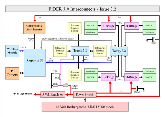
9th November 2018
Final block diagram of PiDER 3.0
I decided not to incorporate a Microbit, to reduce load on the batteries and really it would be a step too far.
The trigger pulse for the kicker/cannon/shooter will come directly from one of the Raspberry Pi GPIO pins.
Two 4700uF electrolytic capacitors have been added. One to each H-Bridge 12V power inputs to help with high current draw when the motors start or accelerate rapidly.
0 notes
Photo

Wi-Fi Alliance starts Wi-Fi 6 certification
The Wi-Fi alliance announced today that it started with Wi-Fi 6 certification.
Wi-Fi CERTIFIED 6 products must be capable of:
Orthogonal frequency division multiple access (OFDMA): effectively shares channels to increase network efficiency and lower latency for both uplink and downlink traffic in high demand environments
Multi-user multiple input multiple output (MU-MIMO): allows more downlink data to be transferred at once and enables an access point to transmit data to a larger number of devices concurrently
160 MHz channels: increases bandwidth to deliver greater performance with low latency
Target wake time (TWT): significantly improves battery life in Wi-Fi devices, such as Internet of Things (IoT) devices
1024 quadrature amplitude modulation mode (1024-QAM): increases throughput in Wi-Fi devices by encoding more data in the same amount of spectrum
Transmit beamforming: enables higher data rates at a given range resulting in greater network capacity
The first products designated Wi-Fi CERTIFIED 6:
Broadcom® BCM4375
Broadcom® BCM43698
Broadcom® BCM43684
Cypress CYW 89650 Auto-Grade Wi-Fi 6 Certified
Intel® Wi-Fi 6 (Gig+) AX200 (for PCs)
Intel® Home Wi-Fi Chipset WAV600 Series (for routers and gateways)
Marvell 88W9064 (4x4) Wi-Fi 6 Dual-Band STA
Marvell 88W9064 (4x4) + 88W9068 (8x8) Wi-Fi 6 Concurrent Dual-Band AP
Qualcomm® Networking Pro 1200 Platform
Qualcomm® FastConnect 6800 Wi-Fi 6 Mobile Connectivity Subsystem
Ruckus R750 Wi-Fi 6 Access Point
Also, the Samsung Galaxy Note10 is the first Wi-Fi CERTIFIED 6 smartphone, and Wi-Fi Alliance expects most leading phones and access points will soon support the latest generation of Wi-Fi.
Press Release: Wi-Fi CERTIFIED 6™ delivers new Wi-Fi® era
2 notes
·
View notes
Text
Digital Modulation and Demodulation Formats -- Managing Modulation and Demodulation | Soukacatv.com
Digital modulation/demodulation formats provide options in terms of bandwidth efficiency, power efficiency, and complexity/cost when meeting a modern communications system’s data-transfer needs.
Modulation and demodulation provide the means to transfer information over great distances. As noted in the first part of this article (see “Basics of Modulation and Demodulation”), analog forms of modulation and demodulation have been around since the early days of radio. Analog approaches directly encode information from changes in a transmitted signal’s amplitude, phase, or frequency. Digital modulation and demodulation methods, on the other hand, use the changes in amplitude, phase, and frequency to convey digital bits representing the information to be communicated.
HDMI Encoder Modulator, 16in1 Digital Headend, HD RF Modulator at Soukacatv.com
SKD32 IPTV Gateway
Household Universal Encoding & Modulation Modulator
SKD3013 3 Channel HD Encode Modulator
With growing demands for voice, video, and data over communications networks of all kinds, digital modulation and demodulation have recently replaced analog modulation and demodulation methods in wireless networks to make the most efficient use of a limited resource: bandwidth. In this second part, we explore how some higher-order modulation and demodulation formats are created, and how software and test equipment can help to keep different forms of modulation and demodulation working as planned.
Enhancing Efficiency
Efficiency is a common goal of all modulation/demodulation methods, whether they involve conserving bandwidth, power, or cost. Digital modulation/demodulation formats, in particular, have been found able to transfer large amounts of information with minimal bandwidth and power. While increased data capacity tends toward increased complexity in digital modulation/demodulation, high levels of integration in modern ICs have made possible communications systems capable of reliable, cost-effective operation with even the most advanced digital modulation/demodulation formats.
Reasonable bandwidth efficiency is possible with standard digital modulation formats, such as amplitude-shift keying (ASK), frequency-shift keying (FSK), and phase-shift keying (PSK). By executing additional variations, more complex digital modulation formats can be created with improved data capacity and bandwidth efficiency, as measured in the number of digital bits that can be transferred in a given amount of time per unit amount of bandwidth (b/s/Hz).
For example, with minimum-shift keying (MSK), essentially a form of FSK, peak-to-peak frequency deviation is equal to one-half the bit rate. A further variation of MSK is Gaussian MSK (GMSK), in which the modulated signal passes through a Gaussian filter to minimize instantaneous frequency variations over time and reduce the amount of bandwidth occupied by the transmitted waveforms. GMSK maintains a constant envelope and provides good bit-error-rate (BER) performance in addition to its good spectral efficiency.
By applying some small changes, it is also possible to improve power efficiency. Quadrature PSK (QPSK) is basically a four-state variation of simple PSK. It can be modified in different ways—e.g., offset QPSK (OQPSK)—to boost efficiency. In QPSK, the in-phase (I) and quadrature (Q) bit streams are switched at the same time, using synchronized digital signal clocks for precise timing. A given amount of power is required to maintain the timing alignment.
DVB-T And ISDB-T Encoder Modulator
Dual HD Input Modulator With ISDB-T And DVB-T Modulation
SKD121X Encoding & Multiplexing Modulator
In OQPSK, the I and Q bit streams are offset by one bit period. Unlike QPSK, only one of the two bit streams can change value at any one time in OQPSK, which also provides benefits in terms of power consumption during the bit switching process. The spectral efficiency, using two bit streams, is the same as in standard QPSK, but power efficiency is enhanced due to reduced amplitude variations (by not having the amplitudes of both bit streams passing at the same time). OQPSK does not have the same stringent demands for linear amplification as QPSK, and can be transmitted with a less-linear, more-power-efficient amplifier than required for QPSK.
The Role of Filtering
The bandwidth efficiency of a modulation/demodulation format can be improved by means of filtering, removing signal artifacts that can cause interference with other communications systems. Various types of filters are used to improve the spectral efficiency of different modulation formats, including Gaussian filters (with perfect symmetry of the rolloff around the center frequency); Chebyshev equiripple, finite-impulse-response (FIR) filters; and lowpass Nyquist filters (also known as raised-cosine filters, since they pass nonzero bits through the frequency spectrum as basic cosine functions).
The goal of filtering is to improve spectral efficiency and reduce interference with other systems, but without degrading modulation waveform quality. Excessive filtering can result in increased BER due to a blurring of transmitted symbols that comprise the data stream of a digital modulation format. Known as intersymbol interference (ISI), this loss in integrity of the symbol states (phase, amplitude, frequency) make it difficult to decode the symbols at the demodulator and receiver in a digitally modulated communications system.
An ideal filter is often referred to as a “brickwall” filter for its instant changeover from a passband to a stopband. In reality, filters do not provide an ideal reduction in signal bandwidth due to the need for some amount of transition between a filter passband and its stopband; longer transitions require more bandwidth.
Filters for digital modulation/demodulation applications are regularly characterized by a parameter known as “alpha,” which provides a measure of the amount of occupied bandwidth by a filter. For example, a “brickwall” filter, with instant transition from stopband to passband, would have an alpha value of zero. Filters with longer transitions will maintain larger values of alpha. Smaller values of filter alpha result in increased ISI, because more symbols can contribute to the interference.
Modeling and Measuring
A wide range of suppliers offer modulators and demodulators in various formats, from highly integrated ICs to discrete components. A number of those highly integrated transceiver ICs can be used for both functions—as transmitters/modulators and receivers/demodulators. Some are even based on software-defined-radio (SDR) architectures with sufficient bandwidths to serve multiple wireless communications standards and modulation/demodulation requirements.
Modeling software helps simplify the determination of requirements for a communications system’s modulation/demodulation scheme. Some software programs provide general-purpose modulation/demodulation analysis capabilities, allowing users to predict the results of using different analog and digital modulation schemes. For example, the Modulation Toolkit (Fig. 1) from National Instruments works with the firm’s popular LabVIEW design software to simulate communications systems based on different analog and digital modulation/demodulation formats. The software makes it possible to experiment with different variables, such as carrier frequency, signal strength, and interference; and predict different performance parameters, such as BER, bandwidth efficiency, and power efficiency, under different operating conditions.
In contrast, S1220 software from RIGOL Technologies USA simulates ASK and FSK demodulation, in particular for Internet of Things (IoT) applications (Fig. 2). The software teams with the company’s spectrum analyzers to study modulation/demodulation over a carrier frequency range of 9 kHz to 3.2 GHz (and to 7.5 GHz with options). It provides an ASK symbol rate measurement range of 1 to 100 kHz and FSK deviation measurement range of 1 to 400 kHz.
Test instruments are an important part of achieving good modulation/demodulation performance. Numerous test-equipment suppliers offer programmable signal generators, such as arbitrary waveform generators, that can create different modulation formats to be used with or without a carrier signal generator for emulating modulated test signals. Spectrum analyzers provide windows to the modulation characteristics of waveforms within their frequency ranges. And some specialized measurement instruments have been developed for the purpose of testing modulation and demodulation and associated components, such as modulation domain analyzers (MDAs).
A number of different display formats provide ways to visualize modulated signals—with both signal analyzers and software—including constellation diagrams, eye diagrams, polar diagrams, and trellis diagrams (for trellis modulation). For example, separate eye diagrams can be used to show the magnitude versus time characteristics of two separate I and Q data channels, with I and Q transitions appearing as “eyes” on a computer or instrument display screen. Different modulation formats will show as different types of displays; for instance, QPSK will appear as four distinct I/Q states, one in each quadrant of the display screen. A high-quality signal creates eyes that are open at each symbol.
Established in 2000, the Soukacatv.com main products are modulators both in analog and digital ones, amplifier and combiner. We are the very first one in manufacturing the headend system in China. Our 16 in 1 and 24 in 1 now are the most popular products all over the world.
For more, please access to https://www.soukacatv.com.
CONTACT US
Company: Dingshengwei Electronics Co., Ltd
Address: Bldg A, the first industry park of Guanlong, Xili Town, Nanshan, Shenzhen, Guangdong, China
Tel: +86 0755 26909863
Fax: +86 0755 26984949
Mobile: 13410066011
Email: [email protected]
Source: mwrf
2 notes
·
View notes