
Statistics
We looked inside some of the posts by apopic and here's what we found interesting.
Average Info
Notes Per Post
7
Likes Per Post
7
Reblog Per Post
0
Reply Per Post
0
Time Between Posts
8 days
Number of Posts By Type
Text
17
Last Seen Tumblr Blogs


Fun Fact
Forty percent of Tumblr users are between the ages of 18 to 25.
Text
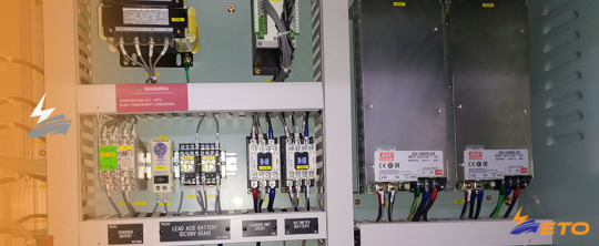
Ship Current Monitoring Relay (over/ under current monitoring relay on ship electrical system)
Ship overcurrent relays are used to protect sensitive equipment against over or under current conditions. By using current transformers (CTs), these protective relays monitor large AC currents common to large motor starters, circuit breakers, and transformers. Ship current transformers CT which steps down the monitored current to a secondary (output) range of 0 to 5 amps (AC) to power the…
View On WordPress
#current monitor relay#current monitor relay on ship#current transformer#inder voltage relay#over current relay#ship monitor relay#ship over current relay#ship under current relay#under current relay
5 notes
·
View notes
Text
How Ship Protection and Monitoring Relays Works
Ship protection and monitoring relays ensure safety and a high level of ship electrical system availability by monitoring electrical power (voltage, current, and frequency).An important function of ship monitoring relays is early error detection. This makes it possible to respond to irregularities before it is necessary to switch off part or all of a ship’s electric system. Ship monitoring…

View On WordPress
#control circuits on ship#el power on ship#monitoring relays#protection relays on ship#ship monitoring relays#ship power system relays
1 note
·
View note
Text
New LNG ship, cooling water and Pre-Hating system
The cooling system runs on the following standard layout: The central freshwater cooling system with single-stage scavenges aircooler and a separate HT circuit. As freshwater is the standard cooling medium of the scavenge air cooler(s), this involves using a central freshwater cooling system. The central freshwater cooling system comprises “low-temperature” (LT) and “high-temperature” (HT)…

View On WordPress
#description of engine room on lng ship#lng main engine#lng ship#lng ship engine room#lng ship engine room maine engine#lng ship main engine#main engine room#modern lng ship#new tehnology on lng ship#pre heating main engine on lng ship#ship on gas#two engine lng ship
1 note
·
View note
Text
Ship electrical contractors and contactor modules
Ship electrical contractors and contactor modules
A simple overview of ship electrical contactor and all contractors accessories. The itemized overview of contactor accessories should help while sending routine ship technical inspections or ship spare orders and when ordering relays or contactors in an emergency. Check basic ship contactor accessory Basic unit Side-mounted (lateral) auxiliary contact module Pneumatic time module (On- and…

View On WordPress
#all anbout ship elecrical contactors#contactor accessories on ship electrical system#contactors on ship#modules on ship electrical contacor#ship system and contactors
0 notes
Text
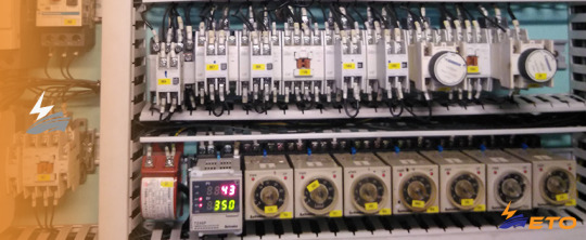
Control relays and timer modules on ship's electrical system
Control relays and timer modules on ship’s electrical system
Contactors and relays from certain manufacturers are constructed to work with a separately top-mounted ‘shock absorber’ mechanism. It is attached as an accessory to the basic unit, preventing immediate full motion of the contacts when the coil is either energized or de-energized. This addition provides the ordinary relay with time-delay actuation. Time-delay modules are constructed to delay…
View On WordPress
#control panels on ship electrical system#problems with ship electrical system#ship timer fault#shipm electrical system#timer modul on elecrical system#timer relays on ship#what is timer relay
0 notes
Text
How is working Mechanical latching modules on ship's electrical system
How is working Mechanical latching modules on ship’s electrical system
Manufacturers supply mechanical latching modules that should be fitted with either control relays or contactors. The resulting devices are called mechanically held relays.Once the closing impulse has been given to the coil (A1-A2), the mechanical latch holds the contactor or the control relay in the closed position without the coil being continually energised. Interruption of the contactor…

View On WordPress
#contactors and addons on ship electrical system#contacts on mechanical latch#impuls for mechanical latch#latching on ship electrical system#ship electrical contactors
0 notes
Text
What is Mechanical Interlock, Mechanical- Electrical Interlock on a ship's electrical system
What is Mechanical Interlock, Mechanical- Electrical Interlock on a ship’s electrical system
The mechanical interlock is assembled between two contactors to prevent them from simultaneously closing and is often used as an added safety feature to electrically interlocked contactors. Even with a mechanical force against the magnetic system, the contacts of both contactors cannot close simultaneously. An electrical interlock consists of two interlinked auxiliary NC contacts. While one…

View On WordPress
#contactors on ship electrical system#contacts on mechanical interlock#interlock contacts#mechanical interlock on ship#mechanicalk force on contactor#ship electrical interlocks
0 notes
Text
Ship Electrical Side-Mounted Auxiliary Contact Modules (Lateral contacts modules)
Ship Electrical Side-Mounted Auxiliary Contact Modules (Lateral contacts modules)
These are used as an accessory for large contactors and are connected through control circuits where they are used for monitoring purposes. Side-mounted contact reference numbers, representing NO and NC contacts, are defined as previously explained. Two position numbers adjacent to each contact terminal. Modules can be from either side of the contactor on ship power system. This means that one…

View On WordPress
#contact modules on vessel#electrical contacts modules#modules on ship contacts modules#ship contacts modules#side mounted contacts#side mounted modules on ship system
0 notes
Text
Ship electrical contactors, description and maintenance
Ship electrical contactors, description and maintenance
A contactor is used to switch larger amounts of electrical power through circuit contacts of 10 amps or higher. Contacts, carrying such a load are called ‘Main Contacts’. These are always NO (normally open) contacts and designated by single digits in pairs: 7-2, 3-4, 5-6 (for three pole contactors), and 7-8 (for four pole contactors). In addition to reference numbers, the following reference…

View On WordPress
#all about ship contactor#contactor on ship#contactors on ship electrical system#maintenance of ship contactors#ship contactor information#ship contactors and maintenance#terminal on contactor
0 notes
Text
How to order a control relay for ship spare parts
How to order a control relay for ship spare parts
When preparing a ship spares order, the reference numbers or letters should not be ignored, particularly If the requested type of relay is not available from the supplier and another vendor is being asked for an alternative. To avoid mistakes it is suggested that the relay order form should include the following information:• Relay manufacturer• type of relay• coil voltage• number of contact…

View On WordPress
#fault relay on ship system#how to buy correct relay#how to order electrical part on ship#how to order relay on ship#mistake ordering relay#order electrical parts on ship
0 notes
Text
Ship electrical system, Top-Mounted Auxiliary Contact Modules
Ship electrical system, Top-Mounted Auxiliary Contact Modules
The modular system is formed around basic units, Which are equipped with additional functions by means of modules. In addition to basic unit contacts, top-mounted auxiliary contact modules offer two or four contact extensions. To prevent duplicating terminal markings when NO and NC contacts are combined, the modules will have different position digits. Picture iustrates the difference between…

View On WordPress
#all about Auxiliary contacts#Auxiliary contacts modul#Auxiliary contacts on ship#ship Auxiliary contacts#Ship power system
0 notes
Text
Voltage Limiting Elements on ship electric network
Voltage Limiting Elements on ship electric network
Electronic equipment such as programmable logic controllers (PLCs), timing relays and coupling modules that can be affected by other components on ship electric network, are commonly used with conventional switching equipment on ship electrical system. For example, disturbances can be created by inductive loads when relays’coils are switched on or off. To reduce the disturbance on ship…

View On WordPress
0 notes
Text
Ship control relays, terminals and working principles
Ship control relays, terminals and working principles
The contacts of electromechanical devices on ship electrical system are utilized through control circuitry only are unlikely to sustain currents higher than 10 Amps. They are called control relays, but are also referred to as relays. Relays are used to controlling and regulate circuits for the indirect control of electric motors, valves and clutches.A modular system is formed around functional…

View On WordPress
#control relays on ship system#dc control relays#ship control relays#Ship electrical system#Ship power system
0 notes
Text
Advantages and disadvantage Solid State Relays on ship power systems
Advantages and disadvantage Solid State Relays on ship power systems
Electromechanical relays can be expensive, large, take longer to work than modern semiconductors and have a finite contact life, particularly for large power contactor relays on big ship electrical systems. Solid state relays, which use thyristors, also known as Silicon Controlled Rectifiers (SCR), Triodes for Alternating Current (TRIAC) or transistor outputs are used instead.The output device…

View On WordPress
#control circuits on ship system#electrical plant on ship#problem with relays on ship#relay on ship electrical plant#ship power systems#ship relays advantages
0 notes
Text
Reed Relays or Electromechanical Printed Circuit Board Relays on ship electrical system
Reed Relays or Electromechanical Printed Circuit Board Relays on ship electrical system
A reed relay consists of a reed switch, ie a sealed glass capsule containing two separated overlapping ferromagnetic reeds. A typical reed switch capsule. The capsule is surrounded by an electromagnetic coil. When the coil is energized, the contacts that are normally open are brought together. When the coil voltage is removed, the reeds separate by their own spring tension. The reeds provide a…

View On WordPress
#circuit board relay on ship#reed relays#Ship electrical system#ship electrical system components#ship printed relays#small relay on ship system
0 notes
Text
Magnetic relays on ship power system
Magnetic relays on ship power system
Latching relays allow the circuit to be controlled by using a single pulse to the relay control circuit and are used when a relay is required to maintain its position if the power is interrupted. There are three basic types of latching relays: Magnetic latching relays on ship power system This relay uses one pulse to move the contacts in one direction. A second pulse from a different input is…

View On WordPress
#impulse relay on ship system#latching relay on ship system#magnetic relay on ship system#mechanical relay on ship system#repair relay on ship electrical system#ship powe system
0 notes
Text
All types and contacts on ship power system
All types and contacts on ship power system
The relay is an electro-mechanical switch, consisting of a coil, an armature, and contacts. A current passes through the coil creating a magnetic field that attracts the armature, causing the contacts to move, either making or breaking a connection. The following contacts are known by how they can be thrown: Ship Normally open contacts (NO)When the relay is activated, NO contacts connect the…

View On WordPress
#connections on ship relay#contacts on ship power system#contacts on ship relay#ship relay and connection#type of electrical relays on ship
0 notes