
Statistics
We looked inside some of the posts by cudatox and here's what we found interesting.
Average Info
Notes Per Post
141
Likes Per Post
111
Reblog Per Post
29
Reply Per Post
1
Time Between Posts
6 months
Number of Posts By Type
Text
13
Video
2
Photo
2
Last Seen Tumblr Blogs


Fun Fact
Tumblr has a 66 index score for customer satisfaction in the US.
Text
Why don't my 3D printed threads work?
There are a lot of potential reasons for this, but the one I have observed most frequently is insufficient tolerance between one or more contact surfaces in printed fasteners.
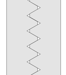
When most people try making threads for the first time, they will often try extruding a triangle along a helical path, resulting in a thread that looks something like this when viewed in profile:
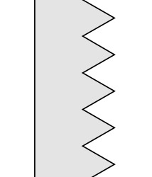
This looks like a thread, but it is unlikely to work as expected. If you tried to print a nut and bolt using this thread, they would very likely jam and refuse to engage more than a few of the threads. If we look at a profile view of the two fasteners threaded together, it's easy to see why:
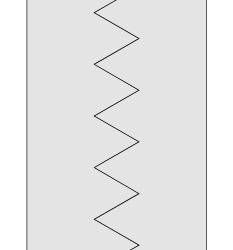
There is literally no gap between the threads!
In a perfect world, this would work fine. However, we live in an imperfect world. 3D printers have limited resolution and like most machining processes, the 3D printing process leaves artifacts of the machining process behind. These artifacts distort the threads and leave small amounts of extra material in some places.
When you tighten these two fasteners together, they undergo some amount of "self clearancing," where small amounts of this excess material is sheared off and/or pushed out of the way. If this extra material has no place to go, the threads simply jam as though someone had filled the threads with dirt prior to you trying to tighten the fastener.
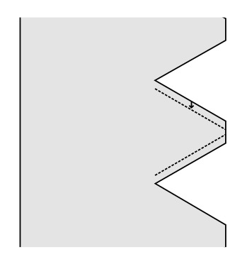
One of the solutions I've observed is scaling the fastener in the XY plane, which simply makes the bolt narrower. This works sometimes, but it is a terrible way to create the necessary clearance because it also ruins the geometry of the threads.
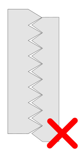
In the image above, the right fastener has been scaled horizontally (ie. in the XY plane if the fastener is vertical). This does create some clearance between the threads, but it also changes the thread angle, resulting in threads that deform or fail under load because forces are concentrated on the very tip of the threads.
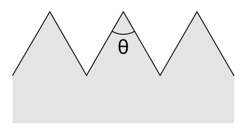
The thread angle represented by theta (θ) in the image above is a critical parameter of threaded fasteners. It is almost always 60 degrees for common fasteners. Scaling the thread non-uniformly changes this critical angle.
So how can we correct these issues?
I combine two techniques to make 3D printed threads that work well: Removing some portion of the tip of the thread and insetting the the edges of the thread profile.
Snipping the tips
Cropping the tips of the threads leaves some space for waste material to go when the threads are tightened. It also helps to account for the fact that the outside edge of the original thread is an infinitesimally small feature (meaning it has zero width) and is thus smaller than the layer height and would result in the creation of printing artifacts anyways.
Note: This does have the downside of creating a helical leakage path for gasses or liquids, but relying on threads alone to create a fluid tight seal is not ideal. In those cases, consider using gaskets or tapered threads.
Insetting faces
Insetting the edges of the thread creates clearance between the angled faces of the thread.
Moving the outside edges of the thread inwards in this manner creates clearance without changing the thread angle. This can, however, create some backlash in the threads which may be undesirable in some applications.
Conclusion
Combining both of these techniques can give you a much better chance of creating threads that work on your particular printer on the first attempt.
But of course, every printer is a little different and requires slightly different tolerances to account for differences in tuning or resolution. So, how does one account for that?
Stay tuned to find out!

0 notes
Text
The Perfect Fastener for 3D Printed Projects
Or rather, the perfect hole
I realized something today while looking for GoPro mounts:
A 1/4 inch US customary screw has a diameter of 6.35mm and an M6 screw has a diameter of, well, 6mm.
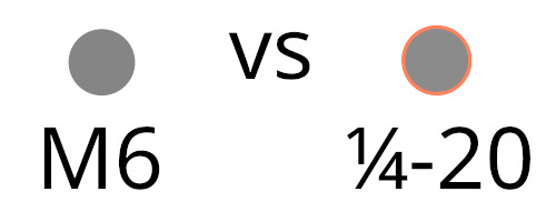
The highlighted area represents the difference in size between these two fasteners, a mere 0.35mm!
This is already very, very close! Many prints designed for use with one can already work with the other... but it gets even better!
The recommended clearance holes (the diameter of the hole that the screws are designed to fit into) for these fasteners differs by less than 0.1mm.
A 1/4-20 fastener requires a 0.257in (~6.53mm) hole, where as an M6 fastener requires a 6.6mm hole.
So a 6.6mm hole will generally fit both a 1/4-20 and an M6 screw without issue!
What about the length?
Metric fastener are generally available in length increments of 5mm, with a few other lengths tossed in. Some of these lengths are largely compatible with their US customary counterparts:
1 inch is approximately 25.40mm, which is a close match to a 25mm fastener. 0.4mm difference.
3/4 inch is 19.05mm, which is a close match for a 20mm metric fastener. 0.95mm difference.
1/2 inch is 12.70mm, which is a close match for a 12mm metric fastener. 0.7mm difference.
So why is this important?
M6 is an extremely common fastener size throughout the world and can be purchased at virtually any hardware store that sells fasteners, except in some parts of North America where metric fasteners are not always available. However, 1/4-20 is an extremely common size in North American stores and is often compatible with designs using M6.
This means that if you use a 6.6mm clearance hole, and are aware of the small differences in length, designs can be made compatible with both M6 and 1/4-20 fasteners.
TL;DR: If your design already uses M6, or could use M6 you can often get cross compatibility with 1/4" US fasteners by using a 6.6mm clearance hole and the fastener lengths outlined above.
So, if you use a 6.6mm clearance hole and design for a 25 -0/+0.4mm fastener, you can guarantee that anyone anywhere in the world can find a compatible fastener for your design since it will fit both a 1/4x1" and M6x25mm screw.
0 notes
Text
I turned my elliptical machine into a mouse so that I can play Runescape while I exercise
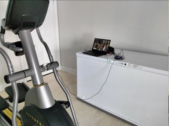
I find simply using exercise equipment to be very boring and I enjoy having something to do while I work out. It's pretty easy to use a phone on a treadmill or exercise bike with the proper mount, but quite a bit more difficult on an elliptical, so I needed a different solution.
Why, though?
This entire project revolves around a single spell in Old School Runescape called "High level Alchemy." In Runescape every item has a general store value and a specialty store value, which is the value in gold peices that you would get from selling that item to a general store or a specialty store respectively. The high level alchemy spell essentially converts an item to its specialty store price in gold pieces. Players will often cast this spell repeatedly on a stack of stackable items in an activity players refer to as 'alching.' This essentially entails clicking a single spot repeatedly until the entire stack has been converted. Now, some less scrupulous players may use a bot to do this, but according to the Rules of Runescape this is not allowed:
"…means using software or hardware that can help you play the game with the software or hardware doing things for you that you should be doing yourself"
So in order to alch items and not cheat, the action must be performed by the player. I think this elliptical machine conversion would therefore be allowed, because the player must pedal it in order to click the mouse. Furthermore, I think the main reason this rule exists is to prevent a player from gaining an unfair advantage using hardware or software, however, this certainly does not give me an advantage. In fact, I would call this a significant disadvantage as I don't think I've ever burned so many calories trying to alch a stack of items before.
How?
I modified a "gaming" mouse from my local dollar store to build this contraption. I picked this mouse up for $4 (CAD) and apart from an RGB LED it seems to be a completely bog standard optical mouse.
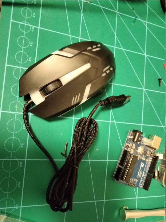
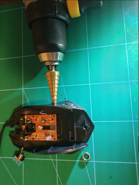
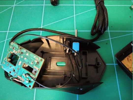
I disassembled the mouse and drilled some holes in it to fit a switch and a headphone jack. I soldered the headphone jack to the mouse button and soldered the switch in series with it. This allows the headphone jack input to be disabled if desired.
In order to "click" the mouse button, some sort of external sensor is needed, so I used a device called a reed switch.
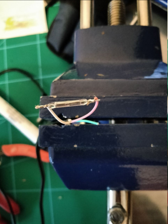
A reed switch is a switch that closes when in the presence of a magnetic field. This is super convenient because it means I can just stick a magnet to one of the moving parts of the elliptical machine and place the reed switch close by. Whenever the magnet moves close to the reed switch, the switch closes and presses the mouse button. When the magnet moves away, the button is released. I soldered this reed switch to a headphone cable, so it can plug into the headphone jack that I installed on the mouse.

The reed switch I used is very fragile as it is made out of glass, so I decided to 3D print an enclosure for it and pot the entire assembly in epoxy. This essentially encases all of the fragile parts in epoxy inside of the enclosure.

I added a loop for a zip tie to the printed enclosure so it can easily attach to the elliptical machine. The magnet can simply stick to the metal parts of the machine. With all this done, all that is needed is to log into Runescape, place your mouse cursor in the right spot and begin your workout.
So does it work?
Yup.
0 notes
Text
Tips for avoiding theft and credit card fraud at conventions
Never use a 3rd party ATM in a hotel or convention center
Always go to a bank, even if it isn't your bank. ATMs in banks are under constant surveillance and regularly inspected for skimmers and hidden cameras. Third party ATMs are often placed in secluded areas an not inspected frequently, which makes them easy targets for fraudsters. EMV (chip and pin) isn’t perfect and there have been successful attacks on the technology in the past, so even these are not always immune to a compromised ATM or payment terminal.
Keep possession of your cards at all times
Since the roll out of EMV, there has been a massive increase in fraudulent card not present transactions (such as online transactions requiring a card number and security code). It only takes a few seconds for someone to snap a picture of your card and security code when you’re not looking, so don’t let your cards out of your sight!
Avoid magstripe transactions

The magnetic stripe data on your card is incredibly easy to copy onto another card and use for fraudulent transactions. This data could easily be captured by a card skimmer or a compromised point of sale system. Pay dealers that only have a magnetic stripe reader using cash or an escrow service.
Keep your receipts
Your receipt is a transaction record that can be used to dispute a fraudulent transaction, particularly in cases where the total listed on the receipt does not match the actual amount you were charged.
In the case of EMV cards, the numbers that you see printed at the bottom of your receipt also contain metadata about the transaction that would be useful to someone investigating a fraudulent transaction.
0 notes
Text
Seven fursuit building mistakes I made that the tutorials didn’t mention
Mistakes I made while building a fursuit that you shouldn’t have to make

I haven’t yet completed this suit and there is still a lot to be done, but for the benefit of others, I’ve decided to document some of the mistakes I’ve made, some of the issues I’ve encountered and some tips I have to share. I’m doing so in the hopes that this will help someone else avoid some seriously frustrating issues.
You probably don’t want ivory colored fur
Ivory fur doesn’t look like natural white fur up close, it looks like dirty white fur.
It might look more natural in online fabric store photos, but you probably want white fur and not ivory fur. The only exception to this rule would be if you’re building something with naturally ivory colored fur such as a polar bear. I know it can be hard to resist just going ahead and buying it, but If you find yourself tempted:
Order swatches
Even if shipping is expensive. I wish I did this. When I started working on this suit, I struggled to find places that sold faux fur in Canada. I eventually found a US based supplier that was able to ship to Canada, but, shipping was expensive and I didn’t have much time. I decided to simply get all of my fur in one order without ordering swatches despite the risks and it was a huge mistake!
This is probably one of my biggest regrets. I ended up ordering ivory fur because it looked better on my monitor than the white fur. It does not, however, look better on a fursuit and I really wish I stuck to the white fur.
Pattern both sides of your fursuit head
Some online tutorials will have you believe that you can pattern one half of your fursuit head and simply flip the pattern over for the pieces of fur for the opposite side. Don’t do it! Some people might be able to pull it off, but unless you’re already very experienced at fursuit making, it’s probably not a good idea. Even minor asymmetry can have a big impact on on the fitment of the fur and cause it to not fit correctly. I had to discard my mostly completed facial fur and completely redo it as a result of this, wasting several hours of time and a great deal of material.
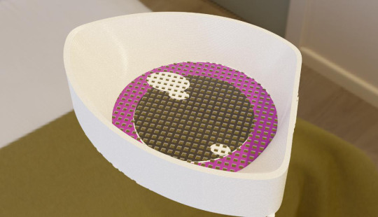
Be careful with the vacuum
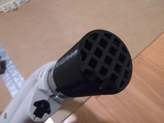
The vacuum cleaner is a great way to remove stray fibers from fur after shaving. Unfortunately, it’s also a great way to remove your entire work piece if you’re not careful! Small pieces of fur can easily get sucked up by the vacuum and this can be quite a frustrating experience after spending a great deal of time shaving down a piece of fur.
I eventually got so frustrated with this that I designed a mesh cover for my vacuum to prevent this from happening. If you have access to a 3D printer, I highly recommend printing one as well.
Try a variety of marking and cutting tools
When building a suit, much of your time is going to be spent marking and cutting fur. Every maker has their own favorite methods for cutting fur, so it’s worth trying a few different tools and techniques to see what works best for you. I’ve been using a very sharp craft knife (similar to a scalpel) to cut the backing of the fur, because that’s what I’ve found to work best for me. Some makers prefer to use utility knives and others prefer to use scissors. I struggled with using a utility knife for a great deal of time because that was the tool recommended by most of the tutorials I looked at. I really wish I had tried using a craft knife earlier, though as I found it to be much more accurate and easier to use.
Use the tools available to you
Use your printer to make templates, stencils and patterns. If you have access to a 3D printer, use it. I used a 3D printer to print the eyes and nose on this head. It’s easy to lose paper patterns and templates, so having digital versions of them could save you some frustration in the future.
However, you don’t have access to these tools, don’t let that stop you! You absolutely can build a suit using simple hand tools and do not need need to buy a 3D printer or even a sewing machine (though it is recommended). I’ve probably stitched more of my suit by hand than I’ve machine sewn at this point, so you can definitely get by with just hand stitching.
You’re going to make mistakes
I made a lot of them. Don’t get discouraged. If you mess up some part of your suit, you can always try it again! It’s okay to take extended breaks if you need to or go back and do some more research on how to make a particular part.
7 notes
·
View notes
Text
Fixing my GeeeTech i3 3D Printer Megapost, Part 1: Electronics
As of this post I’ve owned my GeeeTech i3 Pro B for nearly two years, discovered a lot of problems with it and made a great many modifications to it to correct those issues. I’ll maintain a list of the issues I’ve encountered here and the steps I’ve taken to correct them for the benefit of anyone that happens to own one.
Please keep in mind that these are my personal experiences and the solutions presented here should not necessarily be taken as advice.
1) GT2560 Controller issues.
Marginal MOSFET performance
USB power glitches
Lack of freewheeling protection on fan output
Inadequate power connector
2) Wiring harness issues
Improperly terminated cables
Use of two separate circuits for power delivery
Potentially hazardous voltages exposed to the user
1) Controller Issues
The GT2560 is a 3D printer controller plagued by a lot of issues and I’ve made many repairs and modifications to it throughout the time I’ve owned one. I’ll discuss some of the issues I’ve had here, discuss some of the things I’ve done to correct them and link to some resources on how to correct some of these issues. It is worth mentioning, though, that I am no longer using a GT2560 and I’ve replaced it with an MKS Gen 1.4.
Poor MOSFET performance: The MOSFETS used for controlling the hotend and heat bed on the GT2560 have marginal performance at best and get quite hot in operation. This is due to the fact that they have a relatively high gate threshold voltage and a high drain-source resistance when on. This is not only an issue because they get quite hot, but also because they dissipate a lot of the power that could be going into the heated bed or hot end as waste heat. The MOSFET in use is a STP55NF06L, the gate of which is driven directly from a microcontroller pin, so we can expect a Vgs of no more than 5v. According to the datasheet for this part, this should result in a drain-source resistance of 0.02Ohm, which would be quite acceptable, however, there is an issue with this design. The high level output of a microcontroller pin tends to dip a bit below the supply voltage for that chip due to internal voltage drops. In the case of the ATMEGA2560 used on this board, the output voltage of an IO pin may be as low as 4.2v:

(From Page 355 of the ATMEGA2560 datasheet)
This voltage is very close to the gate threshold voltage of the FET, as we’ll see below:
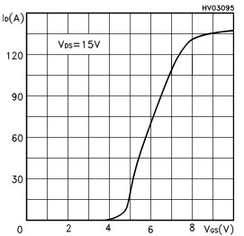
(ST Microelectronics datasheet for STP55NF06L, page 6)
This would result in a high drain source resistance and cause the transistor to dissipate a lot of power. There’s an excellent article about this issue and how to fix it here. On my particular board, I only replaced the FET controlling the heated bed and left the others as they were.
USB power glitches: After a few weeks of using my 3D printer with a single board computer plugged into the USB port, I noticed that the printer would reset itself frequently. After some experimentation, I discovered that plugging my pedestal fan into the same outlet while the printer was running would reliably cause the printer to reset (!).
After some examination of the datasheet, I determined that this was likely due to the design of the circuit that switches from USB power to the 12v supply.
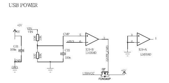
(From the GT2560 schematic)
The circuit above is the one used by the GT2560 to switch off power from the USB port when the 12v supply is connected.
This is more or less the same circuit used by the Arduino Mega, but with one critical difference: the P channel FET used to switch off USB power. The Arduino boards use an NDT2955, which has a minimum threshold voltage of -2v. The GT2560 uses an FDN340P with a minimum threshold voltage of -0.4v. The reason that this parameter is so critical is that when operating at 5v, the maximum output voltage of the LM358 is approximately 3.5v, which means that the transistor used here will still see a gate voltage of -1.5v when the USB supply should be cut off.
At a gate voltage of -1.5v, the NDT2955 used by the Arduino boards will pinch off the current completely because of its higher threshold voltage. However, at that voltage the FDN340P employed here will not turn off completely. This could potentially result in current being fed back into the USB port. Not good!
My solution to this was to print exclusively from an SD card and avoid using the USB port at all.
It might also be possible to fix this by replacing that transistor, but I haven’t attempted it. I think a better solution would be to use a comparator instead of an operational amplifier and use a more appropriate transistor for the task. Perhaps a comparator with an open collector output and a pull up resistor on the gate of the transistor to 12v would be more appropriate. Of course, I haven’t tried any of these proposed solutions, so do so at your own risk!
Lack of freewheeling protection on fan output: Motors are inductive loads. When you shut an inductive load off, it generates a current in the reverse direction of the current previously applied to it. This effect is the so called “flyback effect”.
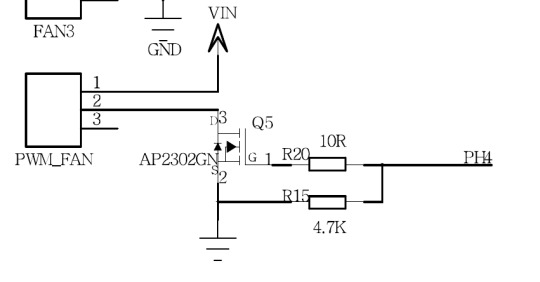
(Portion of the GT2560 schematic showing the failed transistor, Q5)
Of course, that reverse current wants to go somewhere, and in this case, it wants to force itself through the transistor that just turned off. Obviously, this is bad news for the transistor.
This reverse current can cause a large voltage spike across the transistor and eventually lead to transistor failure. The transistor controlling the layer fan on my printer had failed causing the fan to run continuously. After looking at the schematic, I wasn’t terribly surprised to find that there was no flyback protection on the transistor controlling the fan!
The simplest and most common solution to this problem (but not necessarily the correct one in every case!) is to include a freewheeling (or flyback) diode.
I could have simply replaced the faulty transistor and somehow hacked a freewheeling diode in, but I wanted something a bit cleaner. I was able to find a low side power switch in the same device package and pinout as the transistor that had failed, the ZXMS6004FFQTA. It’s essentially an N Channel MOSFET with a bunch of circuit protection built in, including over voltage protection. This is a bit of an expensive solution, but it didn’t require any additional components and corrected the issue without any additional modifications.
Inadequate power connector: The GT2560 appears to use a four pin Molex MiniFit Jr connector (or a clone of it) to deliver power to the board. 12v is delivered on two contacts and ground is connected to the other two. According to the datasheets I found, this connector is rated for 6A continuous per contact. With two contacts providing 12v and two contacts providing ground, we can safely draw a maximum 12A continuously through this connector as this will result in a current of 6A flowing through each contact, though there are some other caveats to this as well which will be discussed later.
The Mk. 2 heated bed uses approximately 10A and the stock Mk. 8 hot end uses about 2.5A for a total of 12.5A. If this printer does indeed use this connector, this puts the current draw of the printer over the current rating of the connector without even considering the current used by the motors.
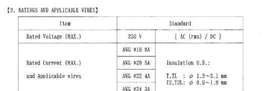
(From https://www.molex.com/pdm_docs/ps/PS-52034-003.pdf)
2) Wiring Harness Issues
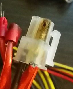
Improperly terminated cables: several of the cables in the wiring harness were not terminated correctly and had poor crimps. Make sure you check your harness, as this is a potential fire hazard. I didn’t discover some of these issues until I actually started disassembling my printer and checking connection resistance with a multimeter.
Use of two separate circuits for power delivery: This isn’t necessarily an issue in of itself, but something to be aware of. If, for some reason, one of the four wires carrying power into the controller got disconnected or had a poor connection, it could cause an unsafe amount of current to flow through one of the other circuits. For example, If one of the 12v wires had a poor crimp on on end, it could snap off and cause all of the current to flow through the other wire carrying 12v. This could easily exceed the current limit of the connector by a factor of two if both the heat bed and hot end were on at the same time.
If this seems like an oddly specific example, that’s because I suspect it’s exactly what happened to my printer:
Potentially hazardous voltages exposed to the user: The terminal block on the power supply for the 115v mains input is located directly above the power switch.
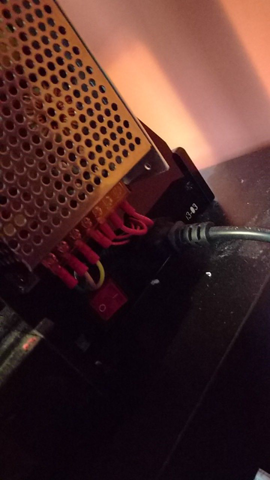
Granted, there is a plastic insulating plate over it, but I really have to wonder why the mains input needs to be directly above the switch. I can’t really see a reason why the power supply couldn’t have been mounted on the other side of the printer, where it wouldn’t be placed so close to a switch that the user needs access to. I ended up temporarily replacing the power supply with an ATX power supply while I was still using the GT2560 with this printer. The 4 pin CPU power connector on a computer power supply is the same type and same pinout as the one on the GT2560.
Conslusion

(Low quality photo, sorry. My phone has poor dynamic range and has difficulty taking photos of dark objects.)
I eventually gave up on the GT2560 as well as the original power supply. I ended up rewiring much of my printer so that I could use an ATX power supply with an MKS Gen 1.4. Surprisingly, this only required a few modifications:
The connectors on the end stop switches had to be replaced with 3 pin JST XH 2.54 connectors
The LCD and SD card headers are backwards compared to the original board, I “fixed” them by cutting the tab off of them with a sharp knife. I also ordered some 2.54mm 10 pin IDC connectors to replace them, but didn’t really find it necessary as I’m the only one that uses this printer.
The fan connector needed to be removed as the MKS Gen uses a terminal block to connect it
I adapted the ATX power supply for use with my printer (there are lots of tutorials on how to do this on the internet). In my case, that meant cutting the ends off of some GPU power connector extensions and crimping some connectors onto them.
I also took this opportunity to crimp some ferrules onto the ends of the bare wires to prevent them from fraying. The board is mounted to the original location using an adapter I designed.
The new setup is performing well and is a marked improvement over the GT2560. I was able to get the latest version of Marlin running on it which includes additional thermal runaway protection, making this printer a bit safer. I’ve also noticed that the hotend and bed heat faster and the FETs controlling them barely even get warm. The MKS Gen isn’t open source, so I can’t easily have a detailed look at how it was designed, but I’ve been using it for the last few days and I’m fairly happy with it thus far.
0 notes
Text
Mathematically defined fursuit claws

I needed claws for my fursuit, but I wanted something totally unique. These claws were 3D printed, but they were not sculpted in a modeling tool or 3D scanned. The shape of each claw is defined by a set of mathematical formulas.
The code to actually generate the claws was written in OpenSCAD (http://www.openscad.org/). OpenSCAD is primarily a CAD tool, but it is very much unlike other CAD tools. In OpenSCAD, models are created by writing code that generates a part. This is very much in contrast to other tools, such as Inventor or Fusion360 in which parts are created interactively.

Most CAD tools are designed for the creation of mechanical components, not organic shapes such as claws. But there are a few features of OpenSCAD that can be used to create these shapes. The hull operation (https://en.wikibooks.org/wiki/OpenSCAD_User_Manual/Transformations#hull) is particularly useful here. The actual claw portion of the model above was created using nothing but 3D primitives and hull operations.
A hull operation essentially takes two three dimensional shapes and fills in the space between them.

This operation makes it fairly easy to create organic looking objects as we can create a few base shapes and and use hull operations between them to create a solid object from cross sections.

In the claw above, the hull operation has been disabled and I’ve replaced the claw profile objects with with flat cross sections.
Where things start to get a little technical, is how the size and locations of the cross sections are computed. As complicated as it may seem, though, the math behind it doesn’t require any knowledge beyond some high school mathmatics. The formulas that define the size and locations of these shapes are simply a pair of quadratic equations!
z = A * x * x + B * x
girth = GIRTH_C - (x * x * GIRTH_A + x * GIRTH_B)
The first formula sets the translation in Z axis of the cross section with respect to the X axis. In other words, the downward shift of each cross section. The second formula sets the size of the cross section, so that it gets progressively smaller towards the tip of the claw. The variables A, B and C are the coefficients of the quadratic equation (https://en.wikipedia.org/wiki/Quadratic_equation).
So, to create the claw, we iterate over each unit of the X axis, compute the size and Z translation of the base shape and hull that base shape with the previous base shape.
pts = [for (x = [0 : X_MAX]) let (z = A * x * x + B * x) [x, 0, z]];
for (x = [1 : len(pts)-1]){
hull(){ translate(pts[x-1]) base_shape(GIRTH_C - ((x-1) * (x-1) * GIRTH_A + (x-1) * GIRTH_B)); translate(pts[x]) base_shape(GIRTH_C - (x * x * GIRTH_A + x * GIRTH_B)); }
}
In the code above, base_shape() is a function that generates a cross section of a given size. To generate the claw shown in the photo I used a three dimensional object instead of a flat cross section.

The idea is the same, but this makes the tip of the claw smooth instead of flat.

This was quite a fun piece of software to write and I’m excited to have the opportunity to use such an unusual, and as far as I know, novel method of creating claws for my fursuit. Expect some more fursuit related posts from me in the future as I continue to build my suit!
6 notes
·
View notes
Photo

A piece of art I made over three years ago was uploaded without my permission to numerous websites without any credit given. Despite the original receiving under one hundred views on FA, it was one of the top search results for “furry wallpaper”. I received almost no recognition for it. So I decided to make an updated, higher resolution version of it (but with a watermark this time!).
FN (4k version): https://beta.furrynetwork.com/artwork/1441256/we-know-4k-background/
Full story: https://np.reddit.com/r/furry/comments/6y6kny/my_artwork_was_stolen_and_is_now_one_of_the_top/
15 notes
·
View notes
Video
tumblr
I never got around to discussing this, but this is a simulator I wrote a few years ago when I was initially designing tails. This sim isn’t terribly accurate, but it still allowed me to quickly predict the effect of design changes and allowed me to optimize my design.
3 notes
·
View notes
Text
Bringing the Tail to a Con (and a few hardware changes)
As I’m sure most regular readers know by now, I was was planning to take my tail to Furnal Equinox. It was a mad rush to get everything done and a few major modifications to the electronics were made, but I’m happy to say that my tail made it to FE.
With a week to go before FE, it very quickly became apparent that my original board was not going to work. I didn’t have time to make a wireless remote for it and it was far too large to fit into my pocket.

The original controller design was huge! It was very nearly 30mm tall without including the battery pack that has to go on the back in order to power everything. There was no way it was going to fit into my pocket. I could have easily made it fit with a custom PCB and surface mount components, but with FE less than a week away, I certainly didn’t have the time to do that.
It was clear that I had to redesign the electronics to fit using parts that I had available.

I quickly got to work designing and etching a new board that I was confident would fit in my pocket. The new board didn’t include a wireless transceiver, but it was small and included four buttons.

This board is based around an Arduino pro mini clone I had sitting around. The pro mini includes an on-board 3.3v regulator and a couple of LEDs, so I didn’t need to add much hardware besides the buttons and a few passives. After assembling the board, I got to quickly porting my code to the new platform. This was actually fairly straight forward as I wrote wrappers around most low level hardware specific functions. I was able to get things working again on the new board in just a couple of hours.
With the new board working, I designed an enclosure for it. I went through quite a few iterations of this enclosure before I was satisfied. I had originally intended to put the battery pack on the back as before, but this made the enclosure too big once again. I later decided to put the battery pack on my belt beside the tail after a friend suggested it.

The controller tucks easily into my pocket, while the batteries stay on my belt (the small piece of electrical tape was added to prevent things like loose change from getting inside the enclosure or shorting the programming header). The battery pack has a simple belt loop screwed into it.
Unfortunately, I ran into issues getting the connectors for the battery pack that I wanted in time and ended up using automotive spade terminals.

These seem to work well in this application as they have excellent vibration resistance and can handle the required current easily. Unfortunately, one of my connectors had a bad crimp and I didn’t realize it until unpacking my tail. It ended up breaking immediately upon removing it from my bag and I wasn’t able to fix it immediately as I had forgotten some of my tools.
Fortunately, I’m not the only furry into electronics and making things and after asking around, I was able to borrow a pair of pliers and temporarily fix it. I forced a pin from one of my buttons through the connector to “uncrimp” it and widen it enough to get the wire back through it. I then recrimped it around the wire. This worked but unsurprisingly, the crimp didn’t really hold too well and I was forced to push the wire back in a few times.
I was able to keep the tail working for the entire con, however. I had a lot of fun using it, and I got to talk to a lot of furries about animatronics and electronics!
I’ll be taking a short break from this project to work on something else but the next step for this project will be working on reducing the noise from the servo. It is pretty difficult to notice in the noisy public con space, but It seems that a few people heard the tail before noticing it was moving.
3 notes
·
View notes
Text
Etching the Tail Mainboard
I decided to try making the board for my tail myself as there are only a few days before FE and I really want to have them done before then. I’m using the positive photo resist method using presensitized boards. Presensitized boards are easier to use as they already have an even coating of photoresist applied to them and all one has to do is remove the opaque protective cover to begin exposing them. I won’t talk about the process itself in great detail here, as information on how to use the positive photoresist etching method is published on many other websites.
I’m using FR4 PCB and I had quite a hard time cutting it. I tried using a pair of shears, a pair of tin snips and a few different saw blades but found that a hack saw with a 32 TPI blade worked the best.
Once the PCB was cut to size, I placed the mask over the photoresist and exposed it using a UV flashlight I purchased on Amazon. It took me several attempts to get the exposure time and developer concentration right, and as you’ll see my first attempts didn’t turn out as well as I would have liked, but I did manage to get a board that should work just fine.

After exposing the board, I submerged it in the developer solution. The developer removes the parts of the mask that were exposed to ultraviolet light and cures the parts of the resist that were occluded by the mask. The developer is just a weak solution of NaOH, but I had some trouble getting the concentration just right. When the first boards didn’t develop correctly, I had initially thought that I may not have exposed them for long enough. However, after some experimentation, I discovered that the concentration of sodium hydroxide in the developer solution was too low. Many sources suggest using 5g of anhydrous NaOH per liter of water, but the scale I was using wasn’t accurate enough to measure a mass that small. So I measured the volume of the NaOH and used its density to compute the mass instead. Unfortunately, the NaOH I was using was exposed to atmosphere because it was stored in a container that didn’t seal well. Anhydrous NaOH is very hydroscopic and absorbs atmospheric water quite easily. The NaOH I was using had absorbed quite a bit of water and this adversely affected my measurements. I ended up using about a teaspoon of NaOH in 500mL of water, but this measurement is probably grossly inaccurate due to the amount of water it had absorbed.
Once the developer had removed the exposed parts of the photoresist, I submerged the board in the etchant.

I’m using the typical FeCl3 etchant at about 0.5mol/L with a bit of added HCl to speed the process up a bit. This worked, but was rather slow. I will probably double the concentration on the next run. The process was fairly simple, I placed the board in a class container full of the etchant and gently agitated the solution by rocking the container back and forth. The copper on the board reacts with the ferric chloride solution to produce copper chloride and metallic iron. The debris in the bottom of the container is actually the iron produced in this reaction. The etching process took about an hour, but would likely be a lot faster in a more concentrated solution.
With the board etched, I drilled out the holes for my through hole components.

I don’t remember what size drill I used for this, but a 0.8mm bit would probably work very well for most of the through hole parts.
I’m not completely satisfied with the final product as there are some small holes and pitting in some parts of the copper, but this is a prototype and the board should work just fine nonetheless. The final boards will be made by a professional PCB fabricator and will be much smaller than this one.
3 notes
·
View notes
Text
Mechanical components completed
I’ve made a few small changes to the mechanics of my tail and I’m now fairly happy with its operation. This will likely be the last change to the mechanical parts of my tail before I take it to Furnal Equinox.

I’ve increased the spacing of the holes where the cables exit to help prevent the cables from getting stuck and stalling the servo as well as added a couple of loops on which to attach the covering for the tail.
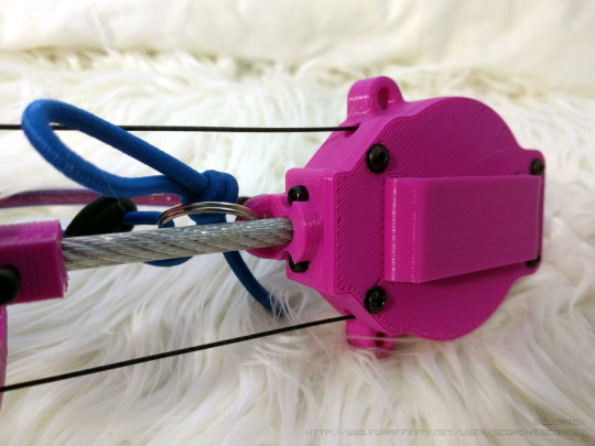
The fur covering for the tail is attached using a pair of plastic toggle stops and some elastic cord looped through a pair of fabric loops sewn into the fur covering.

I’ve also pulled some purple nylon cable braid over the cables and secured it using some heat shrink tubing. I really like the look of the nylon braid and it helps the cable blend in with my belt.
With the mechanical parts of my tail mostly completed, I’m now going to continue to focus on the electronics and firmware.
2 notes
·
View notes
Text
Parts! :D
Its been a while since the last update, but more stuff is coming soon! Until then, have a little peek at what I’ve been up to:

0 notes
Photo


If you’re following me on Twitter, you may have already seen this guy in action :3.
I’ve completed printing the spine discs and pulled the sock over the skeleton. I did a quick test of the new mechanism using my old tail controller, and everything seems to be working correctly mechanically. I've been thinking about using a 3D printer to build a better version of my tail since I finished the first version of it, so I was over the moon when I got this working for the first time! Unfortunately, it does seem like the servo is drawing a bit more current than it should so I’ll be doing some more investigation soon to determine if the servo is defective or if there is some other issue.
The next steps are now designing and programming the new controller. Once I’m done with that, I’ll be building the fursuit sensor and remote control.
7 notes
·
View notes
Text
Ow. My arms.

I really like the look and feel of yarn tails, but couldn’t find a method to create a yarn tail “sock” that could be pulled dover the animatronic skeleton. Yarn tails are typically created by affixing So, I did a few experiments to determine the best method of attaching yarn to a fabric backing.
Placing the yarn flat on the fabric backing and sewing over it using a short zig-zag stitch worked, but the yarn pulled out far too easily when I tried to brush it out.
After thinking about the problem for a bit, I looked up the glass point of acrylic and thought it might be possible to thermally fuse the acrylic fibers. I tried using a hot air reflow station at various temperatures to do this, and had some success, but found that it made the fibers hard and brittle rather than fusing them. This made it much harder to pull the fibers out, but the hot air was hard to control and while it did fuse the fibers to the thread, it didn’t really do a good job of fusing the fibers to the backing.
Then, I realized that the glass point of acrylic is lower than the melting point of hot glue. I tried sewing the individual strands of yarn to the tail and then injecting hot glue into the fibers. This worked wonderfully, and survived brushing without issue. It also held up to a bit of hand washing. When I tried freezing the sample, the glue got brittle and broke up easily, but was sill bonded to the fabric. I used a low temperature EVA glue, but I’m sure there are other types of hot melt adhesive that would work even better.

The tail is roughly 30″ long and it took many, many hours to cut, sew and glue the yarn in place. The brushing alone was a project in itself and my arms are still sore from it, but I’m very happy with how it turned out.
7 notes
·
View notes
Text
More Wags!
The tail is seeing a major upgrade with 3D printed parts and new electronics. It is significantly more compact and sticks out far less than the previous iteration.


This new actuator was designed in Fusion360 and printed in PLA.
The electronics will be moved off of the tail itself and the servo will be connected to the controller via a longer cable, this means the entire assembly is smaller and wont stick out nearly as much. This also grants the user some flexibility in where they wish to locate the batteries and electronics. Here’s a size comparison between the old and new system:

The current project goals are to:
Make the tail wireless
Design a wireless protocol that allows sensors and remote control to interface with the tail
Include optional fursuit detection to make the tail wag when I’m close to a fursuiter
Redesign the tail electronics to be more compact and durable
I hope to have everything ready in time to take this to FurnalEquinox. I’ll be making an effort to document the development process, so many posts are to follow as I continue to work on this.
3 notes
·
View notes