#openscad
Explore tagged Tumblr posts
Visit Tumblr Blog
Explore Tumblr blogs with no restrictions, modern design and the best experience.
Last Seen Tumblr Blogs


Fun Fact
The KCSC sent more than 20K requests to delete posts related to prostitution and porn to Tumblr from January to June 2017.
Text
3D printer fist mitts #4
Hollow Ball Rod End by nipnbite
See: https://www.thingiverse.com/thing:3120529
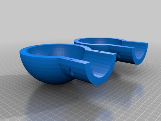
Use 3 M4 X 10mm Button Head Allen bolts and 3 M4 Nuts to hold each mitten together.
OpenSCAD file included.
Hollow Ball Rod End by nipnbite is licensed under the Creative Commons - Attribution license.
27 notes
·
View notes
Text
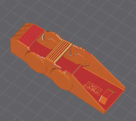
Was talking to someone the other day, telilng them how I don't run my 3D printer much, but have a ton of material I've collected, so I should model something to print. This morning I'm procrastinating and doing just about anything other than writing the artlce I've been banging my head against. So of course, I find myself with some modeling software open working on modeling my default icon. Trying to convince myself that making it multiple pieces that interlock so that it can be multiple colors is definitely a good use of my time, its good CAD practice after all!
2 notes
·
View notes
Text
i finished making the box! it moves even!!
#textpost#3d printing#box#code tofu#video#animation#3d model#openscad#lets hope tumblr can take this video...
11 notes
·
View notes
Text
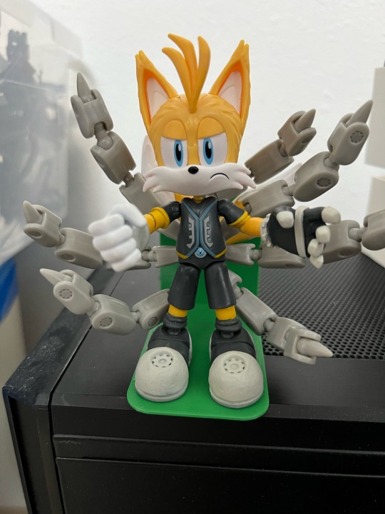
This is my new best friend. You may not touch him.

I designed a little stand for him last night.
#tails the fox#tails nine#3d printing#openscad#overly possessive#you may not like it but this is what peak performance looks like
15 notes
·
View notes
Text
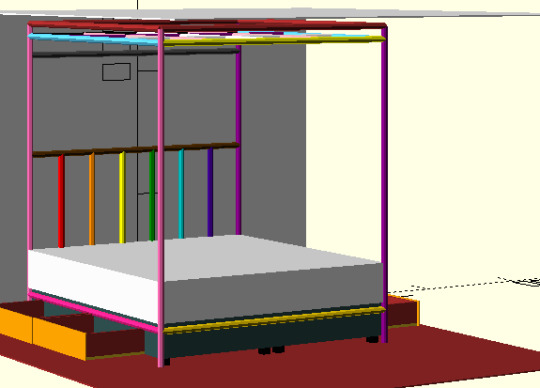
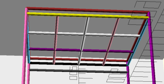
Is it chaser-like to add a trans-flag to my room. It'd seems nice given that more than half of my regular partners are trans (cause they are usually friends of other partners). But maybe frightening.
0 notes
Text
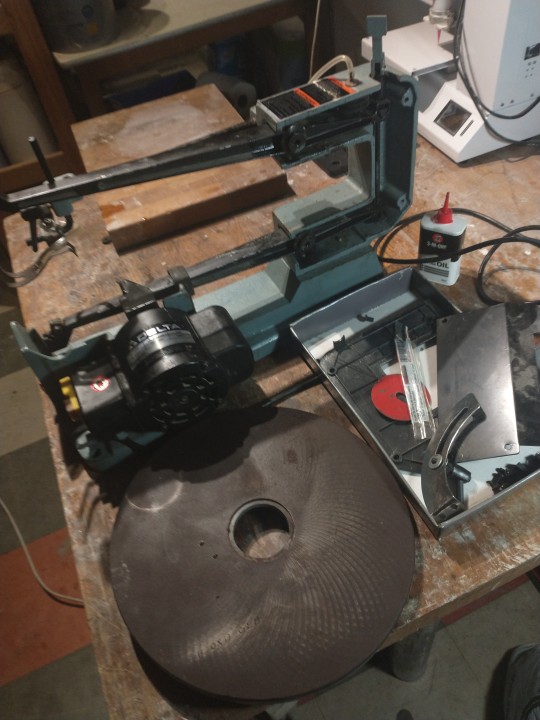
Delta Scroll saw
I bought a scroll saw from the Hackspace where it was surplus equipment. There were two in an auction, both quite old and litlle used. I won one of them for £15 and chose the Delta model since it was the heavier and had a dust blower.
The model is 40-430, single speed. There is a manual for it on-line https://www.manualslib.com/manual/590720/Delta-40-530.html
The machine takes pinless blades of which I already had a few. Pinless blades are finer and come in greater variety than pined blades, which are faster to change. There is a custom tool for blade changing, with a long 4mm Allen key attached to a bar which slots into a hole on the blade holder, setting the key in the right position and locking the hinged holder. It was missing and its fiddly to change blades without, so I need to make a substitute.
Surprisingly the blower works - online advice says the bellows is usually perished.The connecting tube is stiff and should realy be replaced.
At first the machine was very rattley until I realized the the three bolts put though the holes in base were only needed if the machine was going to be permanently fixed to a bench. Much better without and its heavy enough to be stable although it would be better with rubber feet.
Once I'd attached a blade and got the tensioning right, I turned it on and it cut fine and true.
The saw was very dusty and hadn't been used in a while. I took it apart, happy to find all fittings were metric.
A few jobs to do:
free up the table so it tilts
lubricate the pivot bolts
remove the rusty table, sand and polish with wax
(x)replace gnarled cover screws
(x)replace worn blade holder socket head bolts
make the blade change tool with long hex 4mm tool (x) and 5mm threaded (x) bar with 3D-printed spacers
add rubber feet 12mm hole eg https://www.ebay.co.uk/itm/133246278952
x Bits ordered 28/01 £12.50
Blade change tool
I designed a spacer in OpenSCAD to align the long Allen key and a threaded guide bar with M5 nuts to hold it in place. Took a few iterations to get the sizing right but it works fine with three spacers, using lock nuts to fix the spacers in place. The OpenSCAD and STL files are on Thingiverse https://www.thingiverse.com/thing:6460819

Anti-vibration feet
Commercial mounts are surprisingly expensive so I made my own. I had a lot of large tap washers in stock so I made up a stack of one dished and two flat washers below the base, two more flat washers and a metal washer above the base, held together with an M8 coach bolt and nut. This works very well and the saw runs pretty quitely now.

The table
I sanded and oiled the table and it's much improved. Car polish is recommended so I'll do that.
Tilt lock handle
Now that the table has been freed up, the locking mechanism comes into play. It is an M6 bolt with a handle moulded onto it, but the moulding has failed so it can't be fully tightened. Fortunately, it also takes a 3mm Allen key and doesnt need to be adjusted quickly.
Looking better

1 note
·
View note
Text
Technically the 24 hour modeling challenge doesn't really pan out to 24 hours, because I've been rotating models in my brain for this for the past few months. But...
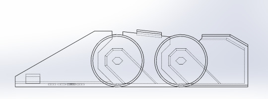
Time to print.
#ooc#3d printing#ik it looks like a reused one but this one is parametric this time#it's constrained to a couple sketches that can be resized to fit your finger#Not sure how to release this in a way that anyone can resize it bc solidworks is kinda.. expensive#not everyone uses it#(i didnt buy it lol)#maybe there's some way to export it into openscad or something
10 notes
·
View notes
Text
aaaaaaaaaaaaaaa my desktop has. debris
9 notes
·
View notes
Text

Because when I think of love, I think of my printer 😬❤️.
1 note
·
View note
Text
Look at open-source software.
Here are some examples:
Ableton Live ➔ Reaper, LMMS, Ardour
Adobe After Effects ➔ Natron
Adobe Animate ➔ OpenToonz, Tahoma2D, Pencil2D
Adobe Audition ➔ Audacity
Adobe Dreamweaver ➔ Blue Fish
Adobe Illustrator ➔ Inkscape
Adobe InDesign ➔ Scribus
Adobe Lightroom ➔ Darktable
Adobe Photoshop ➔ GIMP, Krita
Adobe Premier ➔ Olive, Lightworks, Kdenlive, Shotcut
AutoCAD ➔ OpenSCAD, LibreCAD, FreeCAD
Corel Draw ➔ Inkscape
Corel Painter ➔ Krita, MyPaint
Matlab, Mathematica, Maple ➔ GNU Octave, Scilab, FreeMath, wxMaxima, Sage Math, GeoGebra Classic
Maya, 3dsMax ➔ Blender
Microsoft Excel ➔ LibreOffice Calc
Microsoft Office ➔ LibreOffice, OnlyOffice Desktop Editors
Microsoft Powerpoint ➔ LibreOffice Impress
Microsoft Visio ➔ Dia, LibreOffice Draw
Microsoft Windows ➔ Linux Mint, Pop!_OS, and any other Linux distribution
Microsoft Word ➔ LibreOffice Writer
OneNote ➔ Joplin, XJournal++, Zim
Outlook ➔ Thunderbird
Pinnacle Studio or any Video Editing Software ➔ Kdenlive, Shotcut
Unity, Unreal, GameMaker ➔ Godot, Love2D
#programming#life#art#self love#crafts#design#graphic design#handmade#product design#love#life quotes#pro gwynriel#corporate wellness programs#work in progress#bandcamp#progressive rock#prog rock
8 notes
·
View notes
Note
Do you have thoughts/opinions on implicit modeling for CAD? I know Fusion 360 has an implementation of it, but their add-on packages aren't cheap so I haven't gotten to play with it.
I haven't touched much in the way of implicit modelling, the closest I've probably got is some higher tier programmatic primitives based modelling with things like openSCAD or the much weirder ImplicitCAD that one of my acquaintances was working on.
It definitely seems useful! Being able to define and merge shapes with all sorts of interesting boundary-based effects is a great idea, it's like putting shaders into your modelling system to create fillets. If you want to define a complex space-filling load-aware mesh for 3D-printing the inside of a wing or something you definitely want a tool like this instead of doing it by hand.
3 notes
·
View notes
Text
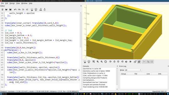
i want to 3d print a box, with this kind of sliding lid, and i'm not sure how to pick my tolerance. the lid is 3mm thick, and will be printed separately.
in hindsight, `lid_margin_bottom` should probably be 0.
6 notes
·
View notes
Note
could i fine-tune an llm to generate svgs? or openscad files?
Totally.
As a proof of concept, GPT-3.5 and GPT-4 are already pretty good at generating SVGs zero-shot. There are some examples here.
25 notes
·
View notes
Text
OpenSCAD: The Programmer's Solid 3D CAD Modeller
https://openscad.org/
2 notes
·
View notes
Text
I love OpenSCAD, but I also wish there was some type of, I dunno, OpenScad 2 or similar. Just like OpenSCAD, but good.
The concept is awesome, sure. Or perhaps more accurately, it fits the way I work and think really well. But it’s so damn limited everywhere. There is no official standard library, just lots you can and have to download, but then there’s no package manager or namespacing to make that easy. I had to implement my own bezier curves. (I probably didn’t have to, I could have downloaded some module that did that, but they’re still not part of the core thing). There is no truly useful way to add bevels and fillets anywhere. In fact, there is no real underlying concept of curves, so you have to write $fn everywhere. Any complex geometry has to be built out of extrusions and transformed cubes and cylinders and spheres. Gears and screws? You’re fully reliant on third party libraries even though these are some very obvious use cases.
It’s cool that I can use modular code to define my functional 3D models for 3D printing, but in practice, everything about it is a goddamn ordeal. Maybe I should go back to try and learn blender, or perhaps FreeCAD.
3 notes
·
View notes
Text
Making a geometry proof for the thingiverse customizer is bonkers who thinks of that
An aperiodic tiling discovery
Much excitement last week with the publication by David Smith, Joseph Myers, Craig Kaplan and Chaim Goodman-Strauss of their discovery of a single tile which tiles aperiodically. Not only that but it does not need any supplementary rules, as Penrose's dart/kite pair do, to ensure aperiodicity. Christian Lawson-Perfect wrote about the story in aPeriodical. Later: There is now an excellent online talk by Craig and Chaim on the discovery and its proof hosted by the National Museum of Mathematics in New York.
The shape was discovered by David Smith, a hobbyist geometer. There is a wealth of research in David's blog, which starts with the declaration "I am not a mathematician but I do like shapes, interesting symmetry, polyhedra, tessellations and geometric patterns. " Skimming though it, one can see the deep exporation of shapes which makes his discovery seem almost inevitable. I plan to read more of his blog for inspiration. Well done ye, David!
The mathematical work of proving that the tile is aperiodic is a masterful exercise, clearly explained. A truly inspiring collaboration between a tinkerer, acedemic mathematicians and computer scientists.
OpenSCAD
Naturally I had a look at this with my OpenSCAD tiling tools.
tl:dr: A customizer on Thingiverse.allows both kinds of tiles in normal or mirror forms and all intermediate tiles to be printed or laser-cut.
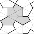
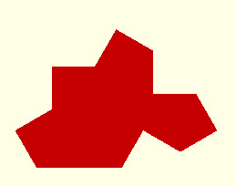
I began by defining the perimeter as a sequence of sides each defined by side length and interior angle taken from the diagram, where we see up of 16 right triangular segments ( 8 kites) of adjacent hexagons. In this formulation, r is the long side of the triangle, a and b the other sides.
function hat_peri(r) = // r is the radius of the base hexagon // returns perimeter as a sequence of [side length,internal angle] let (a = r * sin(60), b = r*cos(60) ) [[b,180],[b,120],[b,270],[a,120],[a,90],[b,120],[b,270],[a,120], [a,90],[b,240],[b,90],[a,240],[a,90],[b,120]];
The first two sides form a straight line but for the purposes of tiling are distinct edges.
The perimeter is converted to a sequence of points using turtle-like geometry:
function peri_to_points(peri,pos=[0,0],dir=0,i=0) = i == len(peri) ? [pos] : let(side = peri[i]) let (distance = side[0]) let (newpos = pos + distance* [cos(dir), sin(dir)]) let (angle = side[1]) let (newdir = dir + (180 - angle)) concat([pos],peri_to_points(peri,newpos,newdir,i+1)) ;

Tiling with this shape requires the use of the mirror image of the base tile:
function reverse(l) = [for (i=[1:len(l)]) l[len(l)-i]];
function mirror_peri(q) = let(p=reverse(q)) [for (i=[0:len(p)-1]) [p[ (i - 1 + len(p) ) %len(p)].x,p[i].y] ];
[This is a bit of a pity. Penrose's tiles are symmetric so the question doesnt arise but the search continues for a monotiling which does not require the use of reflections.]
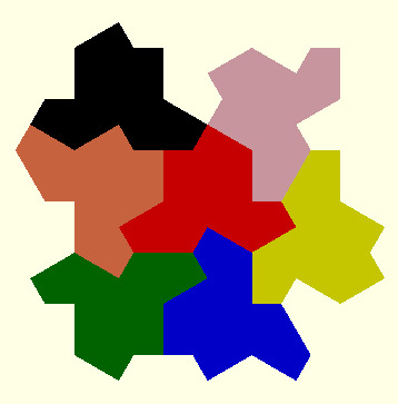
My library of OpenSCAD functions supports the creation of tilings by defining a sequence of edge-to-edge placements. ATM this list is created manually. Each line specifies the alignment of one of the base tiles and edge to a tile and edge in the assembly.
hat_assembly_6 = [ [[0,0]] ,[[0,0],[0,1]] ,[[0,5],[0,2]] ,[[0,3],[0,4]] ,[[0,13],[0,6]] ,[[1,1],[0,9]] ,[[0,7],[0,12]] ];
module hat_tile_6(d) { p = hat_peri (10,d); t=peri_to_points(p); m=peri_to_points(mirror(p)); unit=group_tiles([t,m],hat_assembly_6); fill_tiles(unit,["red","green","blue","yellow","pink","black","coral"]); }
Parametric tiles
More amazingly still, this tile turns out to be one of a family of aperiodic tiles, which in the limit are simple periodic tiles. They are beautifully animated here. The parametric perimeter description enables all members of this family to be constructed:
function hat_peri_family(r,d) = // r is the radius of the base hexagon
// d is the angle which varies from 0 to 90 // returns perimeter as a sequence of [side,internal angle] let (a = r * sin(d), b = r * cos(d) ) [[b,180],[b,120],[b,270],[a,120],[a,90],[b,120],[b,270],[a,120], [a,90],[b,240],[b,90],[a,240],[a,90],[b,120]]);
At the limits , the tiles tesselate:
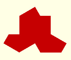
d=0 (nicknamed the comet)
d=45
d=90 (nicknamed the chevron)

All the tiles inbetween are aperiodic:
The Turtle
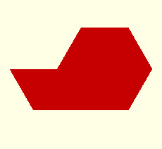
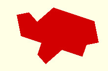
David also discovered a second tile he called the turtle. Defined as a perimeter, this also has 14 sides and is a family of tiles:
function turtle_peri(r,d) = // r is the radius of the base hexagon // returns perimeter as a sequence of [side,internal angle] let (a = r * sin(d), b = r * cos(d) ) [[a,240],[a,90],[b,240],[b,90],[a,120],[a,180],[a,120],[a,270],[b,120],[b,90],[a,120],[a,270],[b,120],[b,90]];
d=60
The periodic endpoints d=0 and d=90 are the same as for the hat.
This is a small section of a tiling in David's blog:
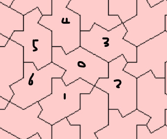
No mirroed tiles in this example.
turtle_assembly_6 = [ [[0,0]] ,[[0,12],[0,13]] ,[[0,13],[0,2]] ,[[0,5],[0,6]] ,[[0,4],[0,7]] ,[[0,5],[0,10]] ,[[0,10],[0,11]] ];
To do
I'd like to add a couple of the suggested decorations.
A big task is to automate the tile placement to construct an assembly. Craig's software does this so I dont expect it to be easy! The approach I'd like to explore (perhaps it's the obvious appraoch?) is to start with the perimeter description of the base tile and extend this as each tile is added. The next tile can be placed by matching a subsequence of the tile perimeter to a subsequence of the expanding perimeter. Bit complicated to ensure that such a match will result in a fit especially with concave shapes.
Further
Veritasium has a nice youtube on the background to aperiodic tiling
Jaap Scherphuis created the PolyForm Puzzle software which was used by David in his explorations.
7 notes
·
View notes