
Dolph was founded in 2001, previous state owner 806 Factory is the predecessor. Based on experience of design and manufacturing nearly two decades, we have been providing reliable products, and winning good reputations.About our product, our process lines include bend waveguide, directional coupler, standard gain feed horn, filter, rotating joint and other modules. We offer all kinds of microwave devices and feed systems. Also our products and solutions played key roles in satellite communication systems and space exploration tasks.High reliability is a symbol of Dolph Microwave. The concept is specified in our “Quality Manual”and“Quality Procedure”using ISO 9001-2000.Knowing the specific requirements of each customer so as to provide satisfactory products and systems. We look forward to cooperating with you in microwave and satellite communication fields. https://www.dolphmw.com/
Don't wanna be here? Send us removal request.
Statistics
We looked inside some of the posts by dolphmicrowave and here's what we found interesting.
Average Info
Notes Per Post
0
Likes Per Post
0
Reblog Per Post
0
Reply Per Post
0
Time Between Posts
50 seconds
Number of Posts By Type
Text
9
Last Seen Tumblr Blogs


Fun Fact
Tumblr was created by web developers David Karp and Marco Arment.
Text
Industrial Microwave Bends

Dolph Microwave offers Industrial Microwave Bends for 915 and 2450MHz, which includes both E-bends and H-bends. All units are precisely bending to the desired angle. At the same time, maintaining a constant cross section to minimize energy reflection. Besides, this family of Industrial Microwave Bends, also boast low loss, and VSWR as low as 1.06:1 and are available in both E-bends and H-bends configurations. Taking the WR340(2450MHz) for example.
Ordering Guide of Industrial Microwave Bends
Datasheet of Industrial Microwave Bends
WR340 Waveguide Bend
Electrical Specifications
Model
DH-26WHB/WEB_A*B
Frequency Range
2.17-3.3 GHz
VSWR
≤1.1:1
Insertion Loss
≤0.05 dB
Mechanical Specifications
Waveguide Type
WR340
Type of Bend
H-Bend/E-Bend
Flange Type
FBP26 (Cover)/FBM26 (Grooved)
Material
Aluminum
Inside Finish
Conductive Oxidation
Outside Finish
Anticorrosion Black/White Paint
Size(mm)
A=** mm, B=** mm
Diagram of Industrial Microwave Bends
FAQs of Industrial Microwave Bends
FAQs of Industrial Microwave Bends
Application of Industrial Microwave Bends
Industrial Microwave Bends is used to guide high frequency signals propagating in a specific direction through the waveguide. Because of these bends, the signal is allowed to change direction within the waveguide, thereby minimizing losses, reflections, and distortions in the electric and magnetic fields.
Features of Industrial Microwave Bends
Industrial Microwave Bends include E-bends and H-bends. E-bends alters or distorts the E-field (electric field) of a propagating signal. H-bends alters or distorts the H-field (magnetic field) of a propagating signal. The bend angle is usually 30, 45 or 90 degrees.
0 notes
Text
Flexible Waveguide
Dolph Microwave manufactures a quality line of flexible twistable/non-twistable waveguides, specially designed to meet all of your requirements. The components is made from a helically wound waveguide core and additional mechanical support is offered from a variety of protective jackets.
The Flexible Waveguide is parts of Feeder line, compared with the rigid waveguide, which is not only reduces the difficulty of connection, but also keep connection accuracy. The Rectangular Flexible Waveguide has E bend and H bend function including twisted function.
Ordering Guide of Flexible Waveguide
Ordering Information of Flexible Twistable Waveguide
Ordering Information of Flexible Twistable Waveguide
Ordering Information of Flexible Non-twistable Waveguide
Flange type: Multiple types available - see Dolph Microwave Flanges page.
Datasheet of Flexible Waveguide
ELECTRICAL SPECIFICATIONS
Waveguide Designation
Freq.Range
(GHz)
Insertion
Loss(dB/m)
Suggested Power Limit
Return Loss (dB)
Peak(MW)
Average(KW)
300mm
600mm
900mm
1000mm
1200mm
1500mm
1800mm
R40
WR229
WG11A
3.22-4.90
0.15
1.6
5
31.0
28.8
28.3
28.3
27.8
27.3
26.3
R48
WR187
WG12
3.94-5.99
0.16
1.4
3
31
28.8
28.3
28.3
26.4
23.1
21.7
R58
WR159
WG13
4.64-7.05
0.18
0.6
2.5
31
28.3
27.8
27.8
26.4
23.1
21.7
R70
WR137
WG14
5.38-8.17
0.25
0.56
2
30.2
27.8
27.3
27.3
26.4
23.1
21.7
R84
WR112
WG15
6.57-9.99
0.3
0.33
1.5
30.2
27.3
27.1
27.1
26.4
23.1
21.7
R100
WR90
WG16
8.20-12.5
0.4
0.22
1
30.2
27.1
27
27
25.2
22.1
19.7
R120
WR75
WG17
9.84-15
0.5
0.18
0.75
29.4
27
26.4
26.4
24
20.93
19.7
R140
WR62
WG18
11.9-18
0.65
0.12
0.4
29.4
26.4
26
26
24
20.93
19.7
R220
WR42
WG20
17.7-26.5
1.2
0.045
0.1
23
22.1
21.1
21.1
-
-
-
R320
WR28
WG22
26.5-40
2
0.022
0.075
21
20.8
20.8
20.8
-
-
-
R400
WR22
WG23
33-50
2.5
-
-
20
16.5
15.6
16
-
-
-
MECHANICAL SPECIFICATIONS
Waveguide Designation
Max Twist(Deg/m)
Min E-Bending Radii(mm)
Min H-Bending Radii(mm)
Static
Repeated
Static
Repeated
Static
Repeated
R40
WR229
WG11A
132
33
165
660
330
1320
R48
WR187
WG12
155
40
136
544
272
1088
R58
WR159
WG13
185
45
116
464
232
928
R70
WR137
WG14
210
52
100
400
200
800
R84
WR112
WG15
260
68
82
328
164
656
R100
WR90
WG16
315
76
66
264
132
528
R120
WR75
WG17
365
92
54
216
108
432
R140
WR62
WG18
445
112
46
184
92
368
R220
WR42
WG20
630
157
30
120
60
240
R320
WR28
WG22
920
230
20
80
40
160
R400
WR22
WG23
920
230
18
78
38
158
*The Standard Model Numbers above are the most common parts ordered for size, material and flange. However, these models can easily be altered to accommodate your needs by using the Model # code system below for complete part number.
** Please refer to the Technical Reference section for flange types/connectors details. Please contact us for your specific requirements.
0 notes
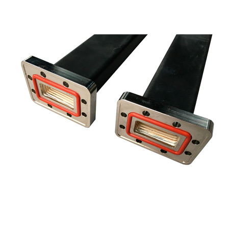
Text
Double Ridged Flexible Waveguide

Flexible waveguide products can be divided into flexible waveguide (interlocked flexible waveguide) and non-twisting flexible waveguide (seamless flexible waveguide). Flexible flexible waveguide has the bending and twisting functions of e-plane and h-plane, while non-twisting flexible waveguide has the characteristics of low loss and good air tightness.
The double-ridged flexible waveguide assembly is mainly composed of inner conductor, flange and outer sheath. The inner conductor is ridged corrugated tube, and the attenuation performance can be greatly improved by surface silver plating. Flange chooses copper or aluminum manufacturing to meet the needs of different customers; The black silicone rubber sheath can protect the soft waveguide and ensure the suitable performance of the soft waveguide in various environments.
Ordering Guide of Double Ridged Flexible Waveguide
Flange type: Multiple types available - see Dolph Microwave Flanges page.
Finish: Corrosion protection plus black top coat.
Datasheet of Double Ridged Flexible Waveguide
Product model
Frequency
(GHz)
VSWR
Loss
(dB/m)
Min. bending radius
Flange
E -(mm)
H -(mm)
DH-580DRWEL...PM
5.8-16
≤1.25
1.5
105
210
FP/FM
DH-650DRWEL...PM
6.5-18
≤1.30
1.65
90
180
FP/FM
DH-750DRWEL...PM
7.5-18
≤1.30
1.65
85
170
FP/FM
DH-1800DRWEL...PM
18-40
≤1.50
3.42
55
110
FP/FM
Advantage of Double Ridged Flexible Waveguide
Wider bandwidth than rectangular waveguides.
Lower cutoff frequency compared to similar sized non-ridge waveguide.
Replacement for planar transmission lines where enhanced power handling is needed in a compact space.
Application of Double Ridged Flexible Waveguide
The double ridge flexible waveguide are used in situations where increased bandwidth is desired. The flexible waveguide allows mechanical movement (expansion and contraction) and also handles any vibration effects. It is often used to connect antenna with the transmitter part of the wireless system when their positions are not fixed a well as the connection of waveguide feeder, which can not only reduce the difficulty of connection of hard waveguide components, ensure the connection accuracy, but also keep the electrical performance unchanged in the state of bending and torsion.
0 notes
Text
Waveguide Components

Dolph Microwave R&D and manufactures various of standard waveguide component, double ridged waveguide components, industrial microwave components, customized waveguide components, satcom antenna and antenna feeds&RF networks for almost any frequency range you are interested in.
One-stop solution is eagered to be offered for customer in field like Telecommunication, Defense, Aerospace, Electronic warfare, Industrial microwave etc.
Each of Dolph microwave manufactured waveguide components, satcom antenna and feed networks are manufactured with the best specifications exceed over your expectation. Most of them meet MIL standard requirements.
Any interested components or need to discuss with us, please call +86-29-8881-0979 or mail to [email protected]
Types of Waveguide Components
Dolph Microwave as leading manufacturer offers high quality and wide range product, which includes standard and double ridged waveguide components, Industrial microwave components, Satcom antenna and feed networks.
Advantages of Waveguide Components
High Performance
Qualified Raw Material
The main advantage of Dolph Microwave product is carrying with low intersion loss and near perfect VSWR (return loss) closed to 1.
Similarities and Differences of Antennas and Waveguides
Similarities
Both antennas and waveguides belong to electromagnetic components.
Antennas and waveguides transmit/received signal by required power and frequency.
Differences
Antennas transmit signals is wireless in a medium normally, however waveguides transmit wireless signals by metal like aluminum, brass and copper.
Antennas can cover various frequency range which is from low and high, but waveguides range is not very broad.
The antenna efficiency can be specified, but wavegiudes gain is defined by the operation mode.
The antenna efficiency and bandwidth are fixed over the specific frequency range, but it also depends on the mode of waveguide.
Antennas are suitable for long distances signal transmission but waveguides are not.
0 notes
Text
DOLPH CUSTOMIZED WAVEGUIDE TO MEET YOUR NEED

Our microwave components are divided into standard and customized components, which can solve the special requirements of customers on flange, dimension, technical parameter and frequency range.
Microwave Customized Products
Dolph Microwave is specialised in design and manufacture of custom RF systems, which is mainly for Government, Military and Defence. Designed to address customer-specific Signals Intelligence (SIGINT) requirements.
We also design and supply fully customised RF systems meeting specific requirements. Complete systems can be provided for mounted or dismounted applications in land or maritime environments. We have an on-site hybrid anechoic chamber where we undertake pre-compliance measurements of our product's electromagnetic compatibility and verify system level performance of antenna systems.
We can offer product and application:
Microwave, Satcom Antennas
FeedHorn & Network Systems
Optical signal transmission
Spectrum monitoring
HF/VHF/UHF
Cellular/ISM bands
Commercial and Military Satcom
Direction Finding
GNSS
EMP/EMC
Process of Customization Service
04
Confirmation of Order
05
Dolph Microwave Datasheet
06
Production Confirmation
07
Delivery
01
Inquiry (technical parameter+drawing)
02
Checking and Eveluation
03
Details discussion
04
Confirmation of Order
Advantages of Dolph Microwave's Customized Waveguide
High Performance
With our highly professional and qualified team, the required parameter will be guaranteed. The customized system will be reliable and complete pre-sale and after-sale service.
Systemetic Test
When finished production and before delivery, each components will be done a systemetic test to assure the delivered components are qialified.
Short Delivery
Promised lead time will be around 4 weeks. For complicated system or components requirement, it will be in priority production to meet delivery requirement.
Popular Waveguide Components
0 notes
Text
Double Ridged Waveguide Tube

Dolph Microwave Double-ridge waveguide tubes are rectangular waveguide tube with two ridges protruding parallel to the short wall. Double-ridge waveguide tube are widely used in antenna and microwave systems since they exhibit low cut-off frequency, broad frequency band, low characteristic impedance, and capability of matching to coaxial cable.
Waveguide Tube Ordering Guide
Flange type: Multiple types available - see Dolph Microwave Flanges page.
Finish: Corrosion protection plus black top coat.
Waveguide Tubing Specifications
Double Ridge Waveguide Tubing Information
WG Model
Technical Specifications
Innner Diameter Size(mm)
Diameter Size(mm)
National Standard
American Standard
Freq. Range
TE10(GHz)
Cut-off Frequency.
A
B
Devi. (±)
E
±▲E
Rmax
R±10%
H
±▲H
C
D
Devi. (±)
TE10
TE20
24JS2000
WRD200D24
2.000~4.800
1.666
4.925
65.79
30.61
0.10
13.00
0.05
1.27
2.59
16.46
0.05
69.85
34.67
0.10
30JS2500
WRD250D30
2.60~7.80
2.093
42.04
18.16
0.08
3.81
0.05
0.51
2.34
11.18
0.05
46.10
22.22
0.10
24JS3500
WRD350D24
3.500~8.200
2.915
8.620
37.59
17.48
0.08
7.42
0.05
0.76
1.47
9.40
0.05
40.84
20.73
0.10
24JS4750
WRD475D24
4.750~11.00
3.961
11.705
27.69
12.85
0.08
5.46
0.05
0.76
1.09
6.91
0.05
30.23
15.39
0.08
36JS5000
WRD500D36
5.00~18.00
4.222
19.10
8.20
0.08
1.60
0.05
0.38
0.33
4.78
0.05
21.64
10.74
0.08
28JS5800
WRD580D28
5.80~16.00
4.892
19.81
9.40
0.08
3.05
0.05
0.38
1.09
5.08
0.05
22.35
11.94
0.08
28JS6500
WRD650D28
6.50~18.00
5.348
18.29
8.15
0.08
2.57
0.05
0.51
0.56
4.39
0.05
20.85
10.69
0.08
24JS7500
WRD750D24
7.500~18.00
6.239
18.464
17.55
8.15
0.08
3.45
0.05
0.51
0.69
4.39
0.05
20.09
10.69
0.08
26JS7000
WRD700D26
7.00~18.50
5.679
17.42
7.87
0.08
2.67
0.05
0.51
0.58
4.39
0.05
19.96
10.41
0.08
24JS11000
WRD110C24
11.00~26.50
9.363
27.080
11.96
5.56
0.08
2.36
0.05
0.38
0.48
3.00
0.05
14.00
7.59
0.08
24JS18000
WRD180C24
18.00~40.00
14.995
44.285
7.32
3.40
0.05
1.45
0.05
0.38
0.28
1.83
0.05
9.35
5.44
0.08
0 notes
Text
Double Ridged Waveguide Switches

Dolph Microwave series model's frequency are covering from 2.60 GHz to 110GHz. Usually, in accordance with drive modes, they can be classified into sub-electric and manual; If by structure, they are classified into sub-E and H-waveguide transfer switches, with rectangular waveguide transfer switches and double ridge waveguide transfer switches. Wave guide switch is commonly used to change the signal pathway in the waveguide transmission system. Taking WRD750 type as below.
Waveguide Transfer Switches Ordering Guide
Flange type: Multiple types available - see Dolph Microwave Flanges page.
Finish: Corrosion protection plus black top coat.
Waveguide Transfer Switches Datasheet
WRD750 Waveguide Electronic Switch
Electrical Specifications
Model
DH-750DWESMDC
Frequency Range
7.5-18.0 GHz
VSWR
≤1.3:1
Isolation
≥50 dB
IL
≤0.4 dB
Handling Power
2000 W (CW)
Switch Speed
120ms
Switch Type
Double Pole Double Throw (DPDT)
Actuator Type
Latching
Actuator Options
TTL Logic, Self Cut Off, Window Indicator,
TTL Control
on: 2.4 to 5.5 Volts
off: 2.4 to 5.5 Volts
Power Voltage
27V±10% ( 0.5A )
Control Interface
6-pin Aviation Plug (Customizable)
Life
≥100,000 Cycles
Mechanical Specifications
Waveguide Type
WRD750
Flange
FPWRD750D24
Ingress Protection Rating
IP67
Pressure
Up to 30 PSIG
Temperature
-40℃~+80℃
Humidity
0-100%
Material
Al/Cu
Inside Finish
Conductive Oxidation
Outside Finish
Anticorrosion Grey Paint
Control Interface Specification
MS3102E14S-6P Connector Pin Instructions
Pin Number
A
B
C
D
E
F
Purpose
Power supply/grounding
Grounding/power supply
Connect to micro switch
Connect to micro switch
Connect to micro switch
Connect to micro switch
Waveguide Sitch Control Interface Signal Definition
MS3102E14S-6P
Definition
Description
A
Power supply/grounding
Switching power supply, when A is connected to +27V and B is grounded for a duration of 120ms±20ms, the switch is in state I (J0 and J1, J2 and J3 are on).
B
Grounding/power supply
Switching the power supply, when A is grounded, B is connected to +27V, and the duration is 120ms±20ms, the switch is in state II (J0 and J2, J1 and J3 are on).
C
Connect to micro switch
Switch state signal, when the switch is in state I, pins C and D are turned on.
D
Connect to micro switch
It is recommended to connect the signal voltage +5V (connect a 100Ω resistor in series)
E
Connect to micro switch
It is recommended to connect the signal voltage +5V (connect a 100Ω resistor in series)
F
Connect to micro switch
Switch state signal, when the switch is in state II, pins E and F are turned on.
Waveguide Switch Design
Wave guide Switches Details
Waveguide Transfer Switches Advantage:
The double ridge waveguide switches have higher performing switch mechanisms. With double-ridged waveguide, a nearly complete short circuit can be made by merely bridging the reduced distance between the ridges. It places switching elements within the gap of the ridges.
Waveguide Transfer Switches Types:
The double ridge waveguide transfer switches mainly used for changing the signal channel of waveguide transmission system, according to drive mode which divided to motorized and manual.
0 notes
Text
Double Ridged Waveguide Horn Antennas

As a professional horn antenna manufacturer, Dolph Microwave manufactures a high-quality line of double-ridged waveguide horn antennas typically used for EMI testing, surveillance equipment, antenna gain and pattern measurement, which available in WRD1800, WRD750, WRD700, WRD650, WRD580, WRD475, WRD200, WRD180 etc. Also, wide band double ridged waveguide horn antenna are still can be offered from 0.2GHz to 40GHz. The most common Gain values available are 4-20dB. Taking wide band double ridged guide horn antenna as example below.
Double Ridged Waveguide Horn Antennas Ordering Guide
Wideband Dual-Ridged Horn Antenna Ordering Information
Ordering Information of Wideband Dual-Ridged Horn Antenna
Double Ridged Horn Antenna Ordering Information
Ordering Information of double ridged horn antenna
Flange type: Multiple types available - see Dolph Microwave Flanges page.
Finish: Corrosion protection plus black top coat.
Double Ridged Waveguide Horn Antennas Datasheet
Model No
Freq Range (GHz)
Gain (dB)
VSWR (Typ.)
Dimensions (mm)
Connector
L
W
H
DH-WDB0.2-2
0.3-2
4-13
2.5
600
510
840
N-Female
DH-WDB0.3-2
0.3-2
4-15.5
2.0
555
350
528
N-Female
DH-WDB0.4-4
0.4-4
6-17
2.0
440
285
448
N-Female
DH-WDB0.4-1
0.4-1
6.5-12
2.0
455
345
530
N-Female
DH-WDB0.8-8
0.8-8
6-15
2.0
284
164
260
N-Female
DH-WDB0.8-8F
0.8-8
4.8-12.5
2.5
110
260
250
N-/SMA-Female
DH-WDB0.8-18
0.8-18
6-15
2.0
220
130
212
N-Female
DH-WDB1-2
1.0-2.0
8-12
2.0
266
186
322
N-Female
DH-WDB1-4
1.0-4.0
5.5-12
2.0
156
108
152
N-Female
DH-WDB1-6
1.0-6.0
5.4-16
2.5
85
154
327
N-Female
DH-WDB1-12
1.0-12.0
6-13
2.0
245
140
200
N-Female
DH-WDB1-18
1.0-18.0
8.0-18
2.0
245
160
210
SMA-Female
DH-WDB1.5-5
1.5-5.0
>10
2.0
280
240
400
N-Female
DH-WDB2-4
2.0-4.0
11.0-14.5
2.0
221
181
327
N-/SMA-Female
DH-WDB2-4H
2.0-4.0
11.9-17.4
2.0
224
154
384
N-/SMA-Female
DH-WDB2-7
2.0-7.0
9.0-14
2.0
154
129
210
N-/SMA-Female
DH-WDB2-8
2.0-8.0
>10
2.0
194
134
270
N-Female
DH-WDB2-10
2.0-10.0
10.0-19
2.0
100
80
120
N-/SMA-Female
DH-WDB2-18
2.0-18.0
6.5-18
2.0
104
84
168
N-/SMA-Female
DH-WDB3-10
3.0-10.0
7.0-15
2.0
112
39
162
N-Female
DH-WDB4-8
4.0-8.0
15.0-19.0
2.0
250
130
349
N-Female
DH-WDB4-20
4.0-20.0
6.0-14.0
2.0
63
43
98
SMA-Female
DH-WDB5-10
5.0-10.0
15.0
2.0
124
104
222
N-Female
DH-WDB5-30
5.0-30.0
10.0-16
2.0
76
61
106
K-/SMA-Female
DH-WDB6-18
6.0-18.0
9.0-15.5
2.0
58
43
91
N-/SMA-Female
DH-WDB5-30
5.0-30.0
10.0-16
2.0
76
61
106
K-/SMA-Female
DH-WDB5-30
5.0-30.0
10.0-16
2.0
76
61
106
K-/SMA-Female
*Indicates Model Number. See Ordering Information for complete part number.
Double Ridged Horn Antenna Design
Double Ridged Microwave Horn Antenna Details
Double Ridge Waveguide Horn Antenna Characteristics
Uniform Gain
Low VSWR
Flexible Mounting Configuration
Double Ridged Waveguide Horn Antennas Uses
For the horn type antenna, the most commonly used method to expand the frequency band is to add the ridge structure in the waveguide part and the horn opening part. The double ridge waveguide horn antenna is commonly used for horn antenna in microwave and EMC measurement. With EMI testing, the immunity and emissions tests typically measure noise containing frequency components spanning a much wider bandwidth.
0 notes
Text
Double Ridged Waveguide Bulkhead Feedthrus

Dolph Microwave offers a standard product line of double-ridge bulkhead waveguide adapter covering the waveguide sizes WRD-180 thru WRD-475. Assemblies include hardware and silicone rubber bulkhead gasket for mounting purposes. VSWR is less than 1.10. Custom waveguide bulkhead flange patterns and waveguide lengths are available upon request.
Bulkhead Waveguide Adapter Ordering Guide
Flange type: Multiple types available - see Dolph Microwave Flanges page.
Finish: Corrosion protection plus black top coat.
Bulkhead Waveguide Adapter Datasheet
Model No*
WG Size
Freq Range (GHz)
Dimensions
Material
Finish
A
B
C
D
DH-110DRBFU…
WRD110C24
11.00-26.5
76.2
25.4
63.5
76.2
6061 AL
Chromated
DH-180DRBFU…
WRD180D24
18.00-40.00
76.2
25.4
63.5
76.2
6061 AL
Chromated
DH-475DRBFU…
WRD475D24
4.75-11.00
108.0
41.4
82.6
101.6
6061 AL
Chromated
DH-500DRBFU…
WRD500D36
5.00-18.00
95.3
35.1
73.2
88.9
6061 AL
Chromated
DH-580DRBFU…
WRD580D28
5.80-16.00
95.3
35.1
73.2
88.9
6061 AL
Chromated
DH-650DRBFU…
WRD650D28
6.50-18.00
95.3
35.1
73.2
88.9
6061 AL
Chromated
DH-750DRBFU…
WRD750D24
7.5-18.00
95.3
35.1
73.2
88.9
6061 AL
Chromated
*Indicates Model Number. See Ordering Information for complete part number.
Waveguide Bulkhead Diagram
Waveguide Bulkhead Details
Waveguide Bulkhead Features
The double ridge WG bulkhead feed unit covers 2.6 GHz to 110.0 GHz(WRD284 to WRD10). This bulkhead waveguide adapter could be tailor-made as customer's need.
Waveguide Bulkhead Application
The double ridge WG bulkhead feed unit will support when a waveguide system must pass through a pressurized wall or cabinet. A heavy mounting flange and a gasket provide secure sealing.
0 notes