
Don't wanna be here? Send us removal request.
Statistics
We looked inside some of the posts by fmp2025 and here's what we found interesting.
Average Info
Notes Per Post
0
Likes Per Post
0
Reblog Per Post
0
Reply Per Post
0
Time Between Posts
14 hours
Number of Posts By Type
Text
17
Last Seen Tumblr Blogs


Fun Fact
The Tumblr app for Google Glass was released on May 16, 2013.
Text
Mechanic: Force and Steam Admission
As mentioned previously - after the generator is synchronised, more steam can be admitted to generate more force pushing against the generator.
This mechanic also doubles as a challenge, because if the grid synchronisation is lost for whatever reason (for example here, the generator breaker is opened), the turbine will rapidly accelerate due to unrestricted force being applied to it.
I believe this will be a challenge for the player as it presents another condition for the players to manage.
In the example video here, the turbine stop valve closes. This is a device which instantly stops steam flow to the turbine in order to protect it. This also causes the turbine to trip, where the control valve rapidly slams shut anyway which achieves the same effect as the stop valve, albeit slightly slower.
0 notes
Text
Mechanic: Synchronisation
The generator is attached to the turbine and must be "synchronised" with the grid in order to generate power. This refers to essentially connecting its output with the grid using a large circuit breaker.
Due to the way synchronous generators work, if you connected a generator to the grid which was not spinning, it would act as an electric motor and attempt to speed up very rapidly to 3000rpm, which is the speed at which the generator produces a 50hz frequency AC current.
Grid physics are complex and I have had to look into them for this project however in this post I will not cover them in too much detail.
The generator can be synchronised using the generator control panel. It features many warning lights ("annunciators") and two gauges - the lower of which shows the generator RPM in a range of 2990-3010, and the upper of which shows the phase difference between the generator and the grid.

In order to use the switch at the bottom to close the generator breaker, both the RPM and phase angle must be perfect; 3000rpm and a phase angle (difference) of zero - for simplicity, both gauges must be pointing straight upwards. Once this is the case, the player may close the generator breaker by moving the switch to the right.
Once connected to the grid, the turbine and generator speed is now forced to remain at 3000rpm because of the way the generator works (although I do not understand the physics behind this, I only understand how it physically happens). Because of this, more steam can be admitted to the turbine without fear of overspeeding the turbine - this in turn generates more force pushing against the turbine, which generates more electricity.
The video above shows a demonstration of the generator being synchronised. As evident, it requires balancing of the control valves in order to keep the turbine spinning at the correct speed. This is one of the real-world operation
0 notes
Text
Mechanics: Turning Gear
In the real world, the turning gear is a device used to spin the turbine when no steam is being let into the blades. This is to stop the turbine shaft from warping/bending under the immense weight of the turbine itself.
In my game, it spins at 16 RPM, and requires manual engagement and enabling. This is done by means of the turning gear control panel

The gauge on the left shows the speed (in RPM) of the actual turning gear. When it is disengaged (I.e. not attached to the turbine shaft), it is independent and can spin freely.
The switch in the middle along with it's DISENG. (standing for disengage) and ENG. (standing for engage) lights are used to engage and disengage the turning gear and show if it is currently connected. When the green disengaged light is illuminated, the turning gear is fully disengaged. When the red engaged light is illuminated, as expected, the turning gear is fully engaged.
If neither are illuminated, the turning gear is in the process of engaging or disengaging - this takes 4 seconds, and requires the players to hold the switch in the engage position for 4 seconds. If they release it earlier, the turning gear will begin automatically disengaging again and so the green light will illuminate once it moves to the fully disengaged position.
This mechanic is used to physically simulate the turning gear's "pinion clutch" (essentially similar to the clutch on a car except it uses a cog-like gear) position and movement, as it does not instantly snap one way or another in real life.
If the system detects the turning gear's RPM does not closely match the turbine shaft RPM, the clutch will not move and a warning light will illuminate - turning gear clutch movement inhibit. This signifies the clutch has been inhibited and cannot move.
The switch on the right simply turns on the motor which spins the turning gear.

(This video has a cut to speed up)
The turning gear speed, being independent, also simulates inertia. When it is connected, but the motor is not running, its speed will dwindle slowly, when it is disengaged and not running, the turning gear will decelerate a lot faster as it is a smaller, much lighter object, with far less inertia and momentum.
0 notes
Text
Panel Layout

My virtual control panel currently uses this layout. I have circled them to create a small key here:
Circled in red relates to turbine and main steam controls
Circled in yellow relates to turbine emergency controls
Circled in blue relates to turbine ancillary controls
Circled in green relates to generator controls
I have laid it out this way for operator ease, although it is not based on any substantial research. First of all, the steam controls are all to the right of the panel as they relate to each other and all of the controls in these sections will influence each other in some way. The annunciators above this panel show the following:

Turbine Trip: turbine emergency shutdown by automatic rapid closure of the control valves that let steam flow into the turbine
Turbine Stop Valve Closure: an emergency backup system to prevent turbine damage has closed - it slams shut mechanically and blocks all steam flow to the turbine in certain conditions
The rest are somewhat self explanatory; they all represent conditions which may cause a turbine trip
The anciliary control panel contains automatic control modes and a device known as a turning gear, which keeps the turbine spinning at low speeds when it is not running. This is immediately to the left of the steam control panel as these controls are often used just before turbine startup, which is done from the steam control panel.

Turning Gear Engaged shows that the turning gear's clutch is engaged with the turbine shaft, when it is out, the gear is not engaged
TCV Automatic RPM control shows that automatic RPM control is active. This means that the computer will modulate the control valves to admit the correct amount of steam to smoothly achieve the selected RPM.
Automatic TCV Control Trip shows that the automatic control system has been shut down automatically.
TCV Automatic pressure control is a placeholder and has not been implemented
Turning Gear Clutch Movement Inhibit simply means that the turning gear's clutch cannot move due to adverse conditions (turbine RPM does not match for example).
The generator panel is further to the left as in future while it is used in conjuction with the steam controls, it will feature a lot more controls, so it is separated slightly to ensure the ancilliary panel can still be located next to the steam control panel.

Some of these annunciators are placeholders; only the lower panel and the top left and top right from the upper panel work.
The upper panel shows general status of the generator, such as the Breaker being open (it is named 52 Generator 1 or 52-G1 for short; the 52 is the standard ANSI code for HV/AC equipment) or the generator having tripped (emergency shutdown).
The lower panel shows inhibit conditions for the main circuit breaker (MCB), which will light up when the generator breaker is commanded to close but cannot due to safety systems.
0 notes
Text
Specialist Practice Experience
My interests lie in nuclear engineering and simulation games, so I naturally do play games which relate to these topics. The particular game which inspired this project, Realistic Boiling Water Reactor, is a frequent hobby for me.
I communicate regularly in their Discord community server and recently I posted about my project's development to gain some insight and feedback from what is very much my target audience. As well as getting opinions, I also spoke to the director of development for RBWR, and informally applied for a development position citing my project as primary experience, and I was accepted.
Recently due to this I have been developing several new mechanics for this game (RBWR) and a handful of them have been posted as official update 'teasers' of which the community has given feedback on.
I am very happy with the opportunity to experience this and gain such valuable insight into my development work, and also to be able to aid in the development of the inspiration of my own project.
0 notes
Text
Justification of Engine
I have selected Roblox as my engine for this project. This is due to the following reasons:
Experience: I have 5+ years of experience in Roblox and with Lua scripting, meaning I am far more proficient in this engine than any other available. This will assist me in producing more ambitious and complex ideas.
Versatility: Roblox provides a virtual environment based on object-oriented programming which allows easy implementation of new scripts and code. It also allows easy addition of models and textures, which simply can be dragged into the asset manager and Roblox will handle the rest.
Audience: Roblox hosts games for free and will allow me to reach my target audience far easier than on any other platform.
A post from a Roblox developer who used to attend the same college as me (who I was told about by my lecturer) has written a post (above) about why Roblox is a viable engine.
I think these factors make Roblox the perfect choice for my game, although I have looked into other options:
Unreal Engine 5
I have experience in UE5 from college, which would help me create a project which is ambitious and very feature-rich.
UE5 is an incredibly versatile engine used in the industry more than Roblox and has been used for many AAA titles, which suggests it would be a good option
Godot
Godot is a 2D engine which I have not used before however it apparently uses a programming language similar to Python, of which I have experience in.
It is highly regarded by many developers for it's interface and versatility.
I did not consider Unity or CryEngine due to my lack of knowledge in C++ and C#.
0 notes
Text
Proposal Change
Due to time management concerns it is clear to me that I will not be able to finish the entire CCR before the end of the project. It is for this reason that I have decided to simulate instead simply the steam turbine and generator elements.
I have chosen these elements specifically due to their interesting simulation logic that would be required. This includes inertia simulation and some interesting types of interpolation which I would like to explore.
I also have looked into a company which produced steam turbines for many Magnox power stations in the UK, including Oldbury and Calder Hall, and also Heysham 2 (an AGR, which was the successor to the Magnox design).
C. A. Parsons has produced steam turbine for these stations, which interests me as they were founded in 1889, and survived all the way until 1997, which shows that their designs are reliable.
I would like to simulate a Parsons turbine specifically due to this.
My goals for this project now are:
Produce a robust and functional simulation of a steam turbine for my game
Produce a control panel for this simulation complete with a few 3D models
0 notes
Text
Evaluation
AO1:
I chose to create a simulation of a Magnox reactor due to my personal interests and my chosen specialism of programming and systems design. I have taken into consideration the real-world design philosophy of the Magnox reactor. I have considered that nuclear power can be a controversial topic and can involve misinformation, so I have ensured my project serves to educate a general audience on why and how they are safe, and the peaceful and sustainable uses of nuclear power. I have also taken into consideration the location of my fictitious power station and how it may affect nearby residents.
AO2:
I chose to specifically simulate a Magnox-type nuclear reactor due to my research informing me that it is a unique and uncommon design of reactor which pioneered the Gas-Cooled nuclear reactor design. My project serves to both inform and educate my audience on this reactor type, and commemorate the type as a whole. I have learned many design specifications and operational practices related to the Magnox reactor type. Originally, I intended to simulate an entire control room, however due to time management, I adapted my project to simulate only a steam turbine.
A03:
I have used research to inform both creative and practical sides of my project. In my primary research, I looked into my personal interests and other simulation games, in my secondary research, I looked into the design philosophy and operational practices of a typical Magnox control room. I have looked into papers that describe these systems in detail and they have interested me by further reinforcing the view that the Magnox is a unique and unusual reactor design. I think these interests have supported my development by reinforcing my desire to simulate the control room realistically, so I can share this information with others in the form of a game.
AO4:
I have explored many programming constructs and practices that I have not previously utilised, including but not limited to quintic interpolation, trigonometric interpolation, and inertia simulation. These were incredibly useful and appropriate to the scheme of my project as I intended to create a semi-realistic simulation experience. I believe I have been fairly effective in mastering these techniques, especially as they resulted in me being accepted for a development position in the game which inspired this project (Realistic Boiling Water Reactor), citing my project as experience in the field of nuclear energy simulation. I found trigometric interpolation most interesting as involves advanced simulation which I simply enjoyed programming.
AO5:
I have experienced many successes and failures in this project. My biggest success throughout this project in my opinion has been refining an advanced turbine simulation. It has been an incredibly rewarding experience and has been enjoyable and interesting. My biggest failure has been being unable to complete the project as a whole and having to limit my submission to simply a steam turbine, however this could also be seen as a positive because I have been able to further refine this simulation to ensure it is of the highest possible quality.
AO6:
My idea was produced by means of research and was predominantly inspired by my own person interests (nuclear engineering and simulation games). I researched these topics further and explored various ideas and topics within these areas, and settled on the Magnox simulation idea due to it’s uniqueness. I also did consider ideas within flight simulation (another personal interest) but based on my modelling capabilities I decided against this idea. I decided to utilise Roblox as my game engine due to my previous experience with the engine and Lua programming, and because it is an engine that I enjoy using. It also provides an easier way to reach my target audience.
AO7:
I have chosen to produce a paper/pdf guide to both educate players on how to ‘play the game’ and also present the project as a whole and its simulation logic. Each control has multiple effects on different systems which do require explanation, and I have conducted playtests on players of other similar games who state that it is difficult to synchronise the generator to the grid even with previous experience in similar simulations, so I believe a guide would be beneficial to my target audience. I have also presented the work in a ‘sandbox’ environment, allowing players to test out the simulation in any way they wish.
AO8:
I have been somewhat effective in reflecting on my targets and past work. I have not set myself enough targets in my opinion and this is something I will improve upon when employing the creative process in future projects. The quality of my reflections and targets were reasonable, however they were at times unachievable (in terms of targets) and not frequent enough. My project plan was useful however, and was set out accordingly, however I did alter it slightly due to a shift in my final proposal. I believe overall the quality could be seriously improved but also was not at an unacceptable level.
0 notes
Text
Documentation: Turbine Physics and Scripting
My turbine physics have been the most complex part of this project and comprise a total of nearly 1200 lines of code. In the main loop function, I will run through some key aspects of my development here:
1: Trip logic
The trip logic is responsible for shutting down the turbine in an emergency, automatically or manually.

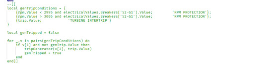
This function contains boolean conditions to automatically trip the turbine. They work by comparing certain boolean values (such as vibrationSimulationValue > VIB_TRIP and rpm.Value > 25 which represents true if the vibrationSimulationValue is in excess of the VIB_TRIP constant) and then iterating over them using a for loop:

Since this runs every frame, the script checks these values and sets another to true if the turbine should trip. If it does, it runs trip functions and breaks the loop. This caused very large issues with the project at first as the turbine kept repeatedly tripping and at the wrong points, which was fixed by breaking the loop.
I also had an with the same logic for the generator - originally, the generator could trip itself, however this caused many issues resulting in the generator not resetting and the turbine tripping instantly. I'm not sure why this was happening but I changed the logic from this:
To simply trip the generator on turbine trip every time. This creates the same effect for the user, but works a lot less problematically. I had the idea to do this based on purely how little it would affect players.
2: Turning Gear logic

This is my current turning gear logic and it involves a variable position pinion clutch. This is actually more realistic, but my original solution was to use delays (task.wait) to 'fake' the turning gear actually having a position.
The original function essentially waited for 5 seconds after the button was pressed, checked it was still pressed, then engaged the turning gear by setting the value to true. This caused issues however, as the user could press it once, then press it again 4 seconds later and it would instantly engage.
Instead of refining this I decided due to it being fairly low quality, I would remake it into this. Now, a percentage (decimal in this case) is used to simulate the position of the turning gear pinion clutch.
This allows for a variable appearance and it realistically simulates the movement of this pinion clutch, rather than simply faking it.
3: Deceleration
Originally, the turbine would deccelerate very rapidly which was unrealistic and not within the goals of my proposal. I wanted it to deccelerate far slower using inertia simulation, instead of very rapidly decelerating to less than half of its max speed within 5 seconds.
While trying to improve a seperate mechanic I changed my TGT_MAX_THRESHOLD constant, which is meant to determine the maximum anticipated (in terms of programming) value to stop some clamps from erroring. They would error because my easing function would return a max value lower than a minimum, so we add a certain threshold to the target RPM to make the actual interpolation goal 750 RPM higher than 3000.
I changed this value to 10000, and this fixed the issue. The reason this happens appears to be because the higher target RPM causes the ease out function to ALWAYS start at its slowest, meaning the effect is much less noticeable.
This however would make it accelerate slowly too, so I added a line of code which interpolates between 0 and 19000 (trial and error tuned value) based on the target RPM:

0 notes
Text
Documentation: Trip Switch & Other Models
I utilised Blender to create some 3D models for my switches and buttons. I used this software due to the fact it is free and I have friends who use this over AutoDesk Maya so I wanted to try it to see if I enjoyed 3D modelling.

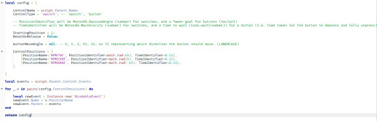
In this case, I used two cylinders and inset their top faces using the edge inset tool.
I can resize this face as I want, but in the case of the "case" for the button I moved it downwards to create an open canister-like shape. I then used the bevel tool to move these faces around to round them and create a more appealing shape.
With the button itself, I simply indented the top face and bevelled the curve to create a smooth print.
These buttons were designed with appearance and also functionality in mind, though I did not animate them in blender as I animated them in Roblox.
0 notes
Text
Documentation: Gauges & Display System
Similar to my switch system, I created a modular display system.
This is not centralised, so each gauge has it's own Script object due to the fact that some gauges move in different ways.

The file structure is similar to the switches, with a Script, BindableEvent (which can be fired by any script and listened by the local script here), and a NumberValue (a class which stores a value) to store essentially the percentage of the gauge's position.

The script is very simple and only sets one property based on what is fired to it using the UpdateValue event.
This works using Tweens which I have explained in a previous post, and by connecting the 'Event' event of the Event to a discrete function using the :Connect() method. This simply allows a function to run when an event is called.
These gauges are easily configurable and utilise a Motor6D class, like the switches, to move. I have used my own plugin to create these:

This plugin simply asks for a Part0 (origin), Part1 (connected part), Pivot (centre of rotation) and parts to weld (any parts connected to Part1) and uses co-ordinate frame calculations to create a Motor6D class using these parameters.
0 notes
Text
Documentation: Switch System
I have produced a modular switch system to aid me in development of my project. This system is designed to allow modular addition of switches without the need to re-script them.
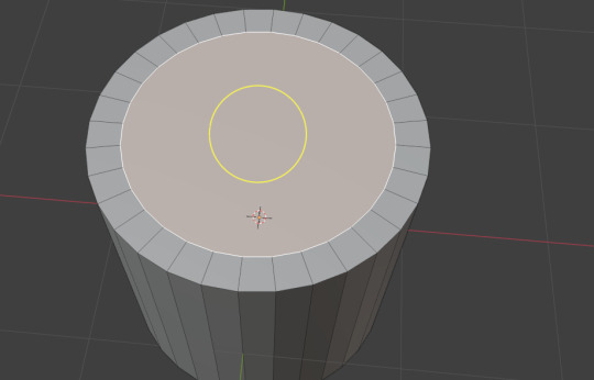
I started by programming a basic Config module, which is a type of script (ModuleScript) which can be accessed from other scripts and returns a value.
You can add a switch position by adding a value to the ControlPositions table, or remove one by removing a value. You can also customise whether the device is a switch or button and the starting position etc.

The script that controls this essentially detects a click using a ClickDetector class, then uses a function to determine the new switch position and sets the physical switch position here. An event is then fired which can be picked up by any other listener script.

The above function is used to determine the next position - it takes a boolean (true representing +1 and false representing -1) and adds to the value, then also clamps this within the amount of existing positions to keep it from overshooting.
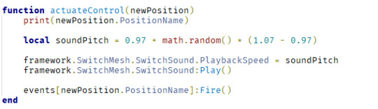
The actuateControl() function takes this position and handles everything else, while the original SetControlPosition function handles the physical switch movement.

Using my models (documented in another post) I compiled everything together in a modular file structure:
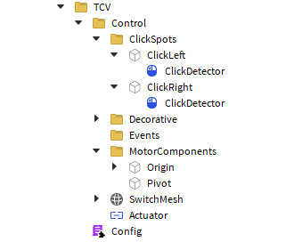
To add a new control I simply need to duplicate an existing one, rename it and then change the config script.
0 notes
Text
Research: Magnox Power Stations
Wylfa
Wylfa is the most recently built and shut down Magnox power station. It uses a different kind of Magnox alloy (Jensen and Nonboel, 1999) and has a generally higher thermal efficiency than the other plants.
I think Wylfa's design will be influential for my project as it was the most recently built, and my simulated station is designed to be more modern than some other types.

Wylfa's location has also influenced my worldbuilding process as it is essentially placed on a small cliff and somewhat close to the town of Holyhead, showing that this positioning would be realistic.
Calder Hall
Unlike Wylfa, Calder Hall is the oldest and first generation Magnox reactor. The power plant had four reactors which could produce 50MWe each, far less than the net output of Wylfa's two reactors. This shows the contrast and improvement in the design.
Calder Hall was built for plutonium production for the UK's nuclear weapons programme, so it may not be influential in the design of my simulated station as mine is designed exclusively for production of commercial energy. Something that does interest me about Calder Hall is the use of cooling towers for cooling water when the station is positioned next to the sea. It and Chapel Cross were the only Magnox stations in the UK to use cooling towers.

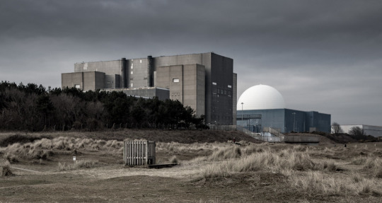
Sizewell A
Sizewell A was a Magnox station in Suffolk, the closest to me. Its design interests me as it had a thermal capacity of 1010 megawatts per reactor, which is higher than Oldbury Power Station despite being older.
Sizewell A's reactor buildings also look very industrial and 'ugly', which interests me and will likely help with designing the buildings in the future (after my project is finished).
Trawsfynydd
Trawsfynydd power station is built on Llyn Trawsfynydd in Wales. It is the most unique Magnox station in my opinion as it is built on a lake and uses cooling water from that lake, instead of the sea.
This has been influential in my worldbuilding process as it has opened up the possibility of 'constructing' my fictitious power station on a lake rather than next to the sea.

Oldbury
Oldbury interests me purely for its physical design. The control room is what inspired my control room design.
youtube
This video has been my primary reference. It shows the interior of the control room.
The exterior also looks surprisingly modern despite it being built in the late 1960s, which will likely influence the exterior design of my station in my game in the future.

Jensen, S. & Nonboel, E. (1999). Description of the Magnox Type of Gas Cooled Reactor (MAGNOX). [online] Available at: https://inis.iaea.org/records/k51h0-aak09 (Accessed: 6 May 2025).
0 notes
Text
Research: Magnox
As the centre-piece of this project, I thought it would be fitting to research more into the Magnox type of nuclear reactor. This research will be useful to my project as it will allow me to make informed decisions relating to the design philosophy and simulation physics of my simulated Magnox reactor.
What is Magnox
The Magnox reactor type is an early British gas-cooled reactor design, meaning it uses gas as its primary fuel coolant. The reactor uses a large graphite block containing empty channels, which are subsequently filled with natural uranium fuel elements in canisters made from an alloy known as Magnox A-12 (magnesium, non-oxidising). Control rods made of boron (a metal which absorbs neutrons exceedingly well) fill the spaces in between these gaps, which can be withdrawn from or inserted into the graphite core to modulate reactivity. When all of the control rods are fully inserted, the nuclear fission process is almost completely stopped. When the boron control rods are fully inserted, The graphite acts as a neutron moderator to "slow down" neutrons released by fission reactions to make them more likely to strike an atom of U-235 (which in turn creates another fission reaction).
Using large blowers known as gas circulators, cooled carbon dioxide gas is blown into the bottom of the graphite core, where it is funneled through empty channels, cooling the fuel elements, and then leaves the graphite core at the top. The exhaust gas is very hot, and is blown into a boiler assembly, which uses a heat exchanger to boil water into steam, which is then used to turn a steam turbine to generate electricty. The heat exchanger in the boiler also serves to cool the carbon dioxide gas, which is then recirculated back into the core.
Some Magnox reactors use very powerful electric motors to turn their gas circulators, whereas others use steam-driven blowers, which are powered by smaller electric motors when the reactor is shut down.
In an emergency, Magnox reactors can be shut down very rapidly by essentially releasing all of the control rods, which fall into the reactor rapidly. This is known as a "reactor trip", and can be triggered manually or automatically.

This diagram showcases the main 'loops' of the cooling water and steam system in a Magnox reactor.
Design Philosophy
One component of the Magnox power stations that particularly interests me is the design philosophy of the control room. Alarms are designed to be "eclipsed" (prioritised) and the control room environment is kept calm and quiet, to assist operators in making decisions.
In comparison to (for this example) a General Electric Boiling Water Reactor (GE BWR) control room, the alarms are much quieter and less abundant, and only alert the operators to the most critical issues, queueing less important alarms to prevent overwhelming operators.
One interesting component I found is the difference in operation of emergency systems. In a GE BWR control room, the reactor can be tripped (in this case a reactor trip is referred to as "SCRAM"). In such control rooms, the reactor can be tripped by pressing two large red buttons simultaneously. These buttons are shown in the image below:

Interestingly, from the information I have been able to find, Magnox control rooms utilise one singular button to trip the reactor (shown below).
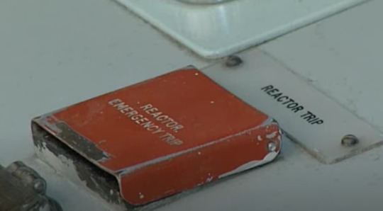
This button appears to be small and discrete, with a red metal cover to prevent inadvertent operation. It also appears to be recessed within a casing, requiring operators to use a single finger or thumb to press the button. I also observed from a video source that I was able to find that the button requires a significant amount of force to press.
youtube
This video also shows the inherent design philosophy of a Magnox CCR; quiet, professional and reserved.
A contrasting video can be found here:
youtube
This video appears to show a training simulator of a more modern GE BWR control room. My immediate takeaway from this video is that the alarms in the GE BWR control room are not prioritised and many activate at once, which in my opinion promotes a confusing, un-organised and potentially even dangerous (due to operators being overwhelmed by the alarms) environment. I also noticed that the operators appear to follow a procedure known as a "SCRAM report", where the reactor operator recites a series of parameters to the shift supervisor in the middle of the room. In the Magnox CCR, this appears to be mitigated by the capability for each control position to directly communicate with each other, which I personally believe to be more reliable and efficient.
This design philosophy (specifically in the Magnox CCRs) interests me and has helped inspire this project as a whole, and I intend to simulate such logic such as "alarm eclipsing" and the interesting design of control interfaces such as the reactor manual trip device.
Examples of Magnox Stations
There are a multitude of Magnox stations in the United Kingdom, and some in other countries such as Italy and Japan, all of which have been shut down and are undergoing decommissioning. Some examples which I will look into further are as follows:
Wylfa in Anglesey, Wales - this station was the most recently built and final to shut down (in 2015).
Calder Hall in Cumbria, England - this station was the first Magnox station to be built and was designed with plutonium production for the UK nuclear weaponry programme in mind.
Sizewell in Suffolk, England - this station is the closest Magnox station to where I reside.
Trawsfynydd in Gwynedd, Wales - this station is the most unique, being built on a lake rather than on a coast.
Oldbury in South Gloucestershire, England - this station appears to have the most references available, and is a 'model' plant on which I am basing my virtual CCR
Berkeley in Gloucestershire, England - this was the first Magnox station to be operated exclusively for commercial power generation (I.e. not for plutonium production).
Other examples of stations that I will not explicitly research for time-saving purposes:
Chapel Cross in Dumfriesshire, Scotland - this station was designed as the sister plant to Calder Hall.
Bradwell in Essex, England - this station was the first to utilise spherical reactor pressure vessels.
Hunterston in Stratchclyde, Scotland - this station was the first and only Magnox reactor to be refueled from the bottom, rather than the top. Hunterston also introduced an automatic reactor trip state, in which if two or more gas loops were out of use, the reactor would be automatically tripped. This would be interesting to research for my project however I am concerned about time management, so I will not research this station for this project explicitly and will instead research it later, after the project is submitted, so I can continue development on my own after I finish college.
Dungeness in Kent, England - this station was the first to utilise steam-driven gas circulators and also had an improved thermal efficiency.
Hinkley Point in Somerset, England. References
Health and Safety Executive. (2013). Better alarm handling [online]. Available at: https://www.hse.gov.uk/pubns/chis6.pdf (Accessed: 6 May 2025).
Health and Safety Executive. (n.d.). Control systems [online]. Available at: https://www.hse.gov.uk/comah/sragtech/techmeascontsyst.htm#fivec9e460 (Accessed: 6 May 2025).
Jensen, S. & Nonboel, E. (1999). Description of the Magnox Type of Gas Cooled Reactor (MAGNOX). [online] Available at: https://inis.iaea.org/records/k51h0-aak09 (Accessed: 6 May 2025).
0 notes
Text
Worldbuilding
I have put together a document outlining my worldbuilding process for my fictitious Magnox power station. I have taken into account locations across the UK and the positioning of existing Magnox power stations, and also some interesting information I found in an IAEA research paper:
The roots of the gas cooled power reactor go back to 1946 where much thought was given to the best type of reactor for plutonium production. The first choice law between a water-cooled graphite moderated reactor and a graphite moderated reactor cooled by gas under pressure, both with natural uranium. The great disadvantage of the water cooled version was the hazard rising from the increased reactivity following an accidental interruption of the cooling water supply. The reactivity increase is caused by the positive void reactivity coefficient. Against this the gas cooled version was safe and therefore could be build in "more accessible regions".
Extracted from "Description of the Magnox type of Gas-Cooled Reactor (MAGNOX), by Jensen and Nonboel, 1999.
The section which I believe will be most influential to my project is the final paragraph; due to the gas-cooled reactor being inherently "safer" than the water-cooled, graphite moderated design.
Interestingly, this information has seemingly been proven; the Chernobyl Nuclear Power Plant, including the reactor involved in the 1986 Chernobyl Disaster, were of a type produced in the Soviet Union known as the "РБМК" (Реактор большой мощности канальный), or RBMK in English, which utilised a similar graphite-moderated, water-cooled design.
This interested me as this shows that the Magnox type of reactor was unique and different from other types. The document I have produced is transcribed below and also attached as a PDF (as I produced it in Microsoft Word due to that being my preferred word processor).
This post outlines the various options and considerations taken for world-building related aspects of my project. The purposes of this project are to provide an enjoyable, fun and educational simulation game revolving around the simulation and virtual operation of a UK-based Magnox nuclear power station. The secondary purposes of this project include educating players on the peaceful uses of nuclear technology (especially relating to global warming and climate change) and to immortalise and commemorate the now-obsolete technical marvel of the Magnox reactor design.
Due to these considerations, it is of the utmost importance and in the best interests of the project that the simulated power station, which will be fictitious, is located in a realistic location and setting, to enhance the fidelity of the simulation and experience in general.
It is worth noting that while ethical considerations pertaining to a modern world are still of importance, the fictitious site would have been constructed at some point from the late 1950s to the early 1970s, to align with the time period during which most Magnox power stations were constructed.
Location:
For the location of the fictitious Magnox plant simulated within this project, several primary sites have been considered, all within the United Kingdom. Each location has been selected for multiple factors that contribute to the placement of real-world Magnox power stations. Taking into consideration the canonical time at which the aforementioned fictitious plant would have been constructed; and also taking into account the ability for such power stations to be placed in ‘more accessible’ locations due to their design (Jensen & Nonbol, 1999).
Site 1: Bradstock, Dorset.
Site 1, Burton Bradstock, in Dorset, England, has been selected for consideration due to its close proximity to a coastline, and acceptable distance from large settlements such as towns and cities. The primary settlements likely to be affected by the plant’s construction would be the villages of Swyre and Pucknowle to the North-East, the hamlet of West Bexington to the East, and the small town of Burton Bradstock, to the North-West. The nearest town with a population exceeding ten thousand is the market town of Bridport, to the North-West.

There are also two local businesses in close proximity to the site which would potentially be affected by the site, Vurlands Animal Farm to the North, and the Orthona Community Retreat Site to the North-West. Research into both of these has been unable to confirm whether or not such business settlements were in existence as of the canon time period.
Considerations must also be made from a practical sense; the site is situated on a slope of slightly more than 100 metres above sea level. This would pose significant challenges in the construction of a Magnox power station, especially during the canon time period (where technological advancements in architecture and materials may not have been sufficiently developed to develop such a feat).
Despite this, perhaps the largest consideration to be made is the presence of the surrounding UNESCO World Heritage Site (of the Dorset and East Devon Coast). While the area was not inscribed on the World Heritage List as of the canon time period, this is still a significant consideration for the world-building process as it may be detrimental to the project’s goals and mission.
Site 2: Camber Sands, East Sussex
Camber, East Sussex has been selected for potential site 2 due to its distance from large settlements, flat and open terrain, and proximity to the coastline with the English Channel. The potential site is situated on the Dungeness headland of Kent, which only possesses a handful of hamlets and villages, and one town. The primary settlements likely to be affected are the village of Camber to the West, the hamlet of Dungeness to the East, the market town of Lydd to the North, and the villages of Lydd-on-Sea and Lade to the North-East. The proximity of Lydd Ranges, a military school and shooting range, must also be taken into account. It is worth noting that the site would actually lie within the county of Kent, however the potential site here has been named after the settlement of Camber and its beach, Camber Sands, which lies in East Sussex.
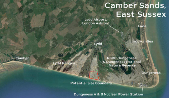
Camber Sands Nuclear Power Station also sits very close to the nearby Dungeness A & B Nuclear Power Stations. It is important to consider the positive and negative implications this may incur:
Positives:
Due to the already-existent nuclear power stations at Dungeness, the surrounding settlements may be accustomed to the presence of nuclear power within the region and may not object to the construction of a third. Taking into consideration that Dungeness B, an AGR power station located next to Dungeness A, which is also of a Magnox type, would not have been constructed in the canon time period.
The proximity of an existing nuclear station may incur the possibility of sharing grid infrastructure such as transmission lines.
The existing railway infrastructure designed for the offloading of spent Magnox fuel elements could prove useful for the fuelling, defueling and decommissioning processes of the fictitious station.
Negatives:
Similar to the first positive, the residents of nearby surroundings may not want an additional nuclear station being built in close proximity.
The existence of two other nuclear stations may suggest that there is not a further demand or necessity for a third in the region, however this could also potentially suggest the opposite due to the proximity with London.
The terrain in the area is sandy and flat. This provides an ideal foundation on which a nuclear station could “easily” be constructed (in comparison with the Bradstock site). The nearest railhead is located just north of the junction connecting Dungeness Road and the smaller Power Station Access Road. This is a privately owned railway station designed specifically for the offloading of spent Magnox fuel, to allow transportation to the Sellafield site in Cumbria.
Site 3: Withernsea, East Riding of Yorkshire
The village of Withernsea in the county of Yorkshire has been selected as site 4 due to its coastal location and proximity to yet isolation from the nearby towns of Kingston-Upon-Hull and Grimsby.

The primary affected settlements would be the villages of Holmpton, Welwick, Hollym, Easington and the larger Withernsea, with secondary settlements being Patrington, Sunk Island, Keyingham, Rimswell and Ottringham. There is a Natural Gas plant located to the south of the site boundary, north of the village of Easington, which suggests industrial installations may be accepted within the region. Further south, there is a national nature reserve (Spurn Heritage Coast) owned by the Yorkshire Wildlife Trust (since 1960), which would likely influence opposition to the plans to build a nuclear power station on this site, however the proximity of the existing industrial site to the north of the aforementioned nature reserve suggests that there may not be much issue with such an industrial installation being placed in the vicinity.
The proximity to Kingston-Upon-Hull would open up many jobs in the region as well. The site is also close in proximity to the North Sea, which would serve as the primary source for cooling water, instead of requiring cooling towers to be constructed.
One downside to the Withernsea site is the aggressive coastal erosion patterns caused by the North Sea. This would require more consideration into coastal defence infrastructure needing to be constructed.
Site 4: Anderby, Lincolnshire
The site of Anderby and its neighbouring holiday village Anderby Creek has been selected due to its distance from major settlements and close proximity to the North Sea. The primary affected settlements would be the hamlet of Anderby to the south-west, the holiday parks of Anderby Creek and Manor Farm Caravan Park also to the south and south-west respectively, and the village of Huttoft to the west. The site would be able to be constructed without disturbing any local buildings or settlements; the only nearby settlement is a farm to the immediate north-west of the site, which would be unaffected directly however likely would oppose the plan due to the proximity. I have been unable to find any information on whether or not this farm was constructed before or after the canon time period in which the Anderby site would have been constructed.
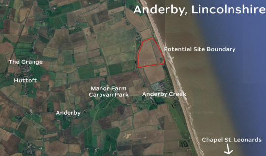
A strong positive for this site is its simplicity and accessibility. The negatives however are the lack of nearby railhead for transportation of spent fuel elements to the Sellafield site. The site also is protected from the North Sea by an abnormally wide sandy beach.
Site 5: Tollesbury, Essex
Tollesbury in Essex has been selected as Site 5 due to its proximity to the River Blackwater for cooling water and its distance to major settlements. The site would predominantly affect only the nearby large village of Tollesbury and its marina. The site is not unreasonably far from the nearest railway (the Great Eastern Main Line where it calls at Kelvedon). Spent fuel elements could be transported by road to a new railway terminal built at the hamlet of Inworth, for loading and transportation to the Sellafield site by rail.

The site is also very close in proximity to the existing Magnox Bradwell Nuclear Power Station, across the River Blackwater (pros and cons of this are outlined in Site 2’s description). The negatives of this site are simply the need to construct new infrastructure which could affect nearby settlements (in the case of the railway terminal, the hamlet of Inworth and the town of Tiptree).
Selected Site:
For the fictitious site of the project, I have selected Site 4 (Anderby, Lincolnshire), as it proves to be the most viable and realistic location for a real world Magnox power station, taking into account the canon time frame and nearby settlements. I have produced a very rudimentary sketch of the vague layout of the virtual station I aim to produce using Adobe Photoshop:

The site here has been sketched from an aerial picture of Oldbury Power Station in South-West England.
References:
Jensen, S. & Nonbol, E. (1999). Description of the Magnox Type of Gas Cooled Reactor (MAGNOX). [online] Available at: https://inis.iaea.org/records/k51h0-aak09 (Accessed: 23 March 2025).
All map and satellite imagery in this post is sourced from Google Maps © Google. These materials are used under the fair dealing provisions of the UK Copyright, Designs and Patents Act 1988 for the purposes of non-commercial research, private study, criticism, or review.
0 notes