
Technology maven, social networker, content marketing, and traveler.
Don't wanna be here? Send us removal request.
Statistics
We looked inside some of the posts by frank-gould and here's what we found interesting.
Average Info
Notes Per Post
0
Likes Per Post
0
Reblog Per Post
0
Reply Per Post
0
Time Between Posts
4 months
Number of Posts By Type
Text
14
Link
1
Photo
2
Last Seen Tumblr Blogs


Fun Fact
69% of Tumblr users are millennials.
Text
This blog is about my technological venture into hardware configuration that I hope will result in a working prototype. This is a hobby to experiment for what a final product could possibly be based on this design. The first concept piece I created can be seen at the following link: Rover Initial Concept Prototype Draft.
Many of the tests turned out to be unnecessary because there was a faster, already implemented solution that only required code to implement. An example of this is the fan-cooling temperature gauge and circuit board. Once I learned RPi reports this with a query, I could turn on the DC power to those fans, at any value up to 255 to start cooling the CPU. Below is the beginning of my journal that started in July after two months of learning curve experiments.
Pan/Tilt Initial Build Results
After soldering the Adafruit 16 Channel PWM/Servo Motors HAT 40 GPIO pins and 8 of the 16 channel three pin connectors (for a total of 64 pins on one board), the pan/tilt worked marginally and inconsistently. Below is a picture of the first successful test.

Thermometer and Cooling Fan Results
To be configured for outdoor use, a fan is an important addition that will at least move cooler air across the circuits once the temperature reaches 150 degrees Fahrenheit inside the unit. To create the circuitry for this feature, I consulted DigiKey who offers an online recipe and schematic editor for creating a thermometer and cooling fan. Below is the schematic I followed to create this feature.

This is the schematic I edited for my final design:


Once I created the breadboard version and it worked, by removing the resistor to the transistor, I created a soldered board that ended up like the picture left.
Fried RPi 3B+ and 16 Channel PWM/Servo HAT
Following the Adafruit 16 Channel PWM/Servo HAT and DRV8871 DC Servo Motor Driver Board installation instructions, I ended up shorting out one of the driver boards that scorched the breadboard, as illustrations follow.


Over time, it appears the 16 Channel HAT shorted out the RPi 3B+ board because it eventually stopped booting and only one LED light lit up and nothing else. These failures caused a redesign and delay for shipping and receiving new parts.

I continued to use these dead RPi and Adafruit boards so I could build rig pieces without stressing the prototype PCBs (Printed Circuit Board). This is where we waited for the RPi3B, RasPiRobot, and PWM boards to arrive on 20 July 2018, which they did, and Phase 1 restarted.
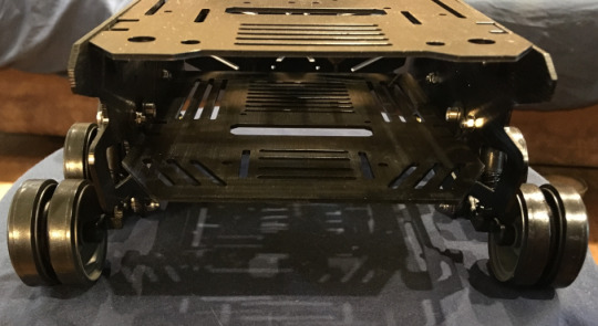
Built Devastator Tank Wheel Base
On 18 July, while waiting for replacement parts, I decided to build the tank wheel base as shown in pictures below. To view the build instructions Click Here.

Below are the wheels with spring shock absorbers mounts.

Below is the rear end where the components will be installed as modules.
Rover Redesign Phase 1 – Version #2
Because I fried a few boards, it became apparent an alternative configuration and boards were needed. Adafruit failed to deliver operable boards and refunded my investment in their products.
Below is a picture of the tested redesign configuration of the DC and PWM servo motors driver boards with Raspberry Pi 3B (not plus).
Note: this is the same SunFounder board was used after the level separators blew the Geekworm PWM/DC Motor board later. Also note that the breadboard contains the 360 PWM calibration circuits that are not connected in this picture to the motor.

23 July – The above configuration failed due to excess power noise caused by the RasPiRobot board that caused video disturbance and ejected the USB drive when attempting to use the PWM channels that resulted in the following message.

After removing the RasPiRobot board, PWM started working consistently for all servo motors, even one marked NFG worked that had failed using the original Adafruit 16 Channel PWM/Servo board.
This same day, I was able to build the new rig, as pictured below.

Then after installing and testing the Geekworm PWM/DC Motor board, the boards sagged (not shown in the picture above) because the lack of support on the top UPS board using only 10 pins for support and without the spacers, one can imagine how the boards will sag when the rover bounces on uneven surfaces.
Then I installed leveling separators between the boards and the Geekworm PWM/DC Motor board began to fail. Here is my report to the manufacturer who had no solution other than work around with a replacement board.

That’s when I decided to modify the M-F jumper wires by bending the Female connector to a 90 degree right angle. To intercept the GPIO pins, because the MoPower UPS does not have GPIO extension pins like the Geekworm HAT (and other similar HATs), these same right angle connectors are installed below the HAT, as shown in the picture below, following the intro paragraph.
Rover Redesign Phase 1 – Version #3
This design is essentially the same Geekworm PWM/DC Motor HAT, however replaced, but now has the 90 degree connectors to reduce the wasted space above the HAT (shown in the picture below).

This new design was made to confirm RPi 3B and 3B+ compatibility and to test the Geekworm HAT without metal separators. I finally found a nylon separator kit, although I only need a few pieces and will have a huge batch left over. These kinds of overages can be used on a second prototype build.
Today, 10 August 2018, we await the arrival of the RPi 3B+ board and Geekworm HAT. During this time, I created a duplicate base plate (plywood sheet) and installed the metal separators using the dead RPi and Adafruit HAT. Once the RPi 3B+ board and Geekworm HAT arrived, I installed the two boards ready to begin testing the new boards.
Remote Control Tablet
As mentioned above regarding the orders placed on 10 August, the Remote Control consists of a RPi 2 designed tablet with touchscreen and battery charging. Below is a link to their tutorial I followed.
Adafruit RPi 2 7″ Touchscreen Tablet Tutorial
These are the Remote Control parts (Flex Cable and SPDT Slide Switch excluded):
Raspberry Pi 27″ TouchscreenLithium Ion Polymer BatteryPowerBoost 1000 ChargerRPi Touchscreen Case (See Below)Wi-Fi Dongle
RPi Touchscreen Case
For the remote control, I finally found that Adafruit tutorial with the recipe of parts needed to make it battery operated. What was unique about this project was the use of a 3D printed case. All I had to do was download the STL files from Adafruit’s website, upload them to the 3DHub.com site, and pay for shipping (total less than $30). Below is the original image of the printed parts (I chose red for fun!).

This turned out to be another variation on hardware integration where finding the right screws makes a whole lot of difference. The variances also require testing a screw to confirm it’s the right head shape: Flat or Round. Because the boards are stacked on the printed tray insert, a Round head can extend up into the back of a stacked board and short out the circuitry. They don’t mention this in the Adafruit tutorial.
So, what I finished the prototype design with regarding screws, I’ve listed below.
TutorialActualM3 x .5 x 6MM3 x .5 x 6M#2-56 3/8″#4-40 1/4″
The problem with the first Metric screws (M3) was that Skycraft carried many varieties of this screw and the first I found had a washer fixed beneath the head that caused the head to rise even higher under the stacked boards. Upon further investigation, I found the same size without the washer and ended up with a more tight fit without possible shorting.
Once I got everything working, I learned I had soldered two wires wrong off the Power Boost Charger 1000. I made this mistake because I didn’t see the – and + signs behind a USB connector that was just setting in sockets and not soldered to the board. The green arrow in the illustration below is what I missed and fried the $20 board by soldering it to the 5V and GND pins next to where the switch is soldered. I took this expense on because I failed to confirm my solder points before I commit, like “measure twice before cutting.”

After I removed the extra piece and saw the electrical schematics, I re-soldering it in the right place, the battery never charged. So, I’m heading back to Adafruit to ask if I’ve burned another board and maybe a battery. Turns out I had fried the LiPO battery charger on the board, so I ordered a replacement. This was when support failed and could not offer an explanation why the battery was not charging. They refunded both of my last purchases and banned me from their site, indefinitely.
Rover Redesign Phase 2 – Version #4
This version change was forced by the RPi3B+ failure and the integration of the RPi3B, Geekworm HAT, and MoPower UPS. During this phase, I redesigned the 90 degree female pin connectors so that there was no black shield included with the contacts and only heat shrink shielded the contacts so less room was consumed by the black shields. This also reduced the labor and glue to hold the black shield, plus the installation was significantly easier.
Also during this phase, I migrated the 360 pan gimbal calibration circuitry to the soldered board along with the temperature switch for the fans. After deciding to migrate the fans from 5VDC to 12VDC, I migrated the fan power to the Geekworm HAT and removed the temperature switch. That way, once the thermometer read above the threshold, the code simply turns the fans on full blast. That’s when we learned one of the 12VDC fans had shorted out and no longer worked (nor could be repaired due to contact location beneath plastic shield).
While testing the PWM for the 360 calibration circuitry, I learned that my solder job had failed and decided it was time to delay the development of the 360 pan feature. Instead, for the prototype, once the 180 pan hits its left or right max radius, the code will instruct the wheels to turn opposite directions to continue the camera pan. This does not remove the requirement for the gimbal 360 pan because the camera should be able to provide 360 views for location and damage mitigation. Below are pictures of the rig with semi-operational features before implementing version #5.
Top of Semi-operational version #4 prototype
Front of Semi-operational version #4 prototype
Right side of Semi-operational version #4 prototype
Left side of Semi-operational version #4 prototype
After migrating to the 12VDC fans and delaying the 360 pan feature, sufficient pins and circuit board became irrelevant and were outside the MoPower UPS 10 GPIO pins requirement. This meant a GPIO 40 pin extension header could be removed and rewired to the Geekworm HAT extension header only (which is why their design failure requires any spacers for this development design).
Right side of Semi-operational version #4 prototype
Left side of Semi-operational version #4 prototype
Rover Redesign Phase 2 – Version #5
After removing the circuit board for 360 gimbal and cooling fans along with their wires, the content of the rover changed considerably, as shown in the pictures below.

During this phase of version #5, I wrote code to use the keyboard to drive the wheels and turn forward and reverse. What’s nice about these motors is when something is going in the wrong direction, like forward and reverse, it’s a simple reverse polarity on the power to fix the direction problem. I had to do that to the power supply wires to the motor connected to the HAT. Once I did that, my code turned the correct wheels (left versus right) and forward/reverse worked successfully. Next to version #6, batteries and secured rig to chassis.
Rover Redesign Phase 2 – Version #6
After creating the rig lock mechanism with Velcro, acrylic side slides, and front key-lock latch, I tried the battery driven vehicle but encountered a failure with the Geekworm HAT. Although it appeared like the previous board I fried, this time it recovered and operated accurately with shore power. I have sent a question to the manufacturer asking how to connect a battery to their board; it may need some kind of regulator. After searching the web for an answer, determined a UBEC needed to be added to regulate the power and it worked. Below is a picture of version 6.

Pan and Tilt Gimbal
Because of the 360 degree pan feature delay, I decided to search again for a python gimbal and found a 3D printer opportunity for a less-flimsy Adafruit gimbal. Below is their glamour shot picture of the parts that are max 4″x4″ and encloses the wiring.

I have sent email to a local 3D printer engineer asking if he can help with plastic residue refinement and tests, as well as contacting the designer of this gimbal via email to ask some specific questions. One question is where to find a switch that is listed in the parts list that I cannot find and how does the camera ribbon cable enter the mounting head’s electronics.
Rover Redesign Phase 4 – Version #7
This section skips a phase because of the many redesigns overlapping each other. This phase is an operational battery-powered prototype with full 360 degree pan and 180 degree tilt gimbal. This required building a wooden rim to hold the gimbal under the glass dome. The full rig design can be seen here. The camera dome design is illustrated below.

Based upon my design RFC (request for change), Ben Holler sent back the gimbal base that 1) fit under the dome (this I learned was serendipitous because I was removing unnecessary legs which would be more for a DSLR camera than the rover) and 2) rotated the screw holes to accommodate the camera ribbon cable. The ribbon cable issue is still under research once the rig dome has been built.
youtube


Here’s the current operational version of the rover, without and with the gimbal.
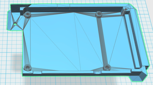
Dome Base Plate – Rig 3D Print Part – Version #8
Because the wood used for the Dome Base Plate cracked the dome due to difficult curves through hard grain, it made more sense to 3D print the part so that the dimensions and fittings are more precise. To do this, I used AutoDesk 123D Design app and built the dome structure plate with the original gimbal base plate.
Original Full Diameter and Depth: 166mm x 20mm, Radius: 83
Changed Full Diameter and Depth: 177mm x 20mm, Radius: 88.5
Dome radius channel to external base top: 70.5 x 15mm (used 71mm radius)
Camera base extrusion channel to dome radius and depth: 67.5mm x 15mm (used 67mm width)
Inner full opening: 22.5mm x 25mm (20mm exceeded to cutout hole)
Bolt holes 5mm and ribbon cable opening 18mm x 2mm
Here’s how it looked close to ready for print:

Next 3D Print Job September 2018
This section is to list the parts that need to be printed again and why.
Rover Dome Base Plate – Picture above was correct but not submitted for print because of errors with the edits. What was printed the center axis of the base is rotated incorrectly as well as the mounting bolt holes in the front and back are way too big.
Rover Acrylic Motor Driver Board – The holes for the micro PCBs are too close to each other and cause the bolts to jut out at angles. Needed to lengthen the main board and separate the left board’s right side from the right board’s left side.
Tablet RPi Holder – This is a design change from the original printed part that separates the RPi mount from the main mount that holds the display board and battery (see picture below).
Tablet Main Mount – This is a design change from the original printed part that remains after separating the RPi Holder.
Rover Gear 14 – Needed to reduce the motor axis shaft opening that allows slippage. Also needed to sand gear burrs on smaller flat side to prevent contacting other parts when moving.
Rover Gear 9 – Needed to edit the gear by flipping the treads or internal slot and to reduce the motor axis shaft opening that allows slippage.
——-
Gimbal Gears Analysis
After spending all day 21 September building the motor driver board test system and rebuilding the gimbal, testing it all and worked closer to expectation than before. Tested it again, this morning, to try calibrating the head to exact coordinates but it eventually failed and locked up, again. After examining the motor-free housing case, the problem appears to be caused by stepper motor gears problem, listed below.
Gear 9 – The gear extends too far over Gear 15 and thus out-of-alignment. Needed to edit the gear to tighten gear shaft opening, like Gear 14. Determined Nylon was best for this and Gear 14 due to heat from motor per Kyle’s recommendation. He said they were better for the heat and being more pliable.
Gear 15 Opening – Needed to be sanded to allow free-spin where it was jamming slightly when spinning. Could be both the gear and the opening.
Gear 14 – Needed sanding of burrs along the short diameter side to prevent catching opening when moving. Also needed tighter gear shaft opening, like Gear 9. Determined Nylon was best for this Gear.
Tablet Redesign – Revision #1
Because Adafruit was unable to support their products, I researched online for other UPS boards that would accomplish the same battery operations without their products. This created the opportunity to improve the original design and upgrade the motherboard to RPi model 3B which includes integrated Wi-Fi support that RPi 2 does not. The RPi 3B version will be the main upgrade for the Tablet Redesign Revision #2.
Below is the list of Revision #1 changes:
Lower the motherboard mount beneath the main mount structure. This helps provide more space for the new battery HAT to be installed on the top of the RPi. Add same screw holes to motherboard mount and add two new screw holes to attach the RPi mounting structure to the main mount.
Remove the PowerBoost mount from the main mounting board.
Add two screw holes to the middle of the case back and lid.
Close case side opening near PowerBoost mount, case over Ethernet connector, and remove switch.
Add bottom case opening to access the new battery board power switch.
Use #4-40×1/4″ screws for the main mount structure and back lid.
Pictures of remote control tablet:

7″ Touchscreen Display and Driver Board with Component Mounting Bracket
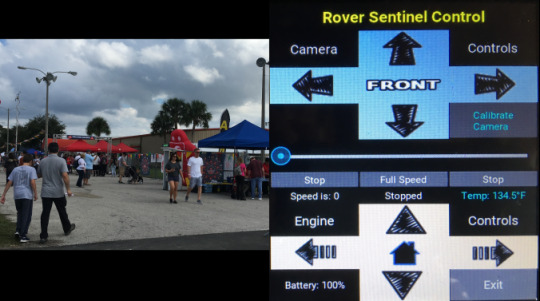
Remote Control User Interface with picture insert of future video feature
First Outdoor Field Test
youtube
Version 8 – Integrated System Complete

23 October 2018 is the date I finally integrated a majority of the parts that all successfully operate. Because the rover needs to be tested in a rough environment, I am holding off testing the larger camera. As a result of the Gimbal pan cable being too short to reach the bottom of the stacked boards, will have to move the DC Stepper Board to the top of the stack, directly beneath the Gimbal base. Currently, the Gimbal cannot go beyond 90 degrees right or it will rip the cable. Also, determined M5 bolts are too large to fit inside the 5mm hole in the Gimbal base (see missing in picture) and replaced that bolt with a M4 bolt.

Picture Above is Right Side of Rig

Picture Above is Left Side of Rig
Version 9 – Integrated System Redesign Complete
The redesign consisted of the following changes that were described in the journal section at the top of this blog. Recap, all worked with the exception of the streaming camera video boot and gimbal with python3, works with python2. Also, remote control tablet is functional with kivy UI. Full System backup of both devices today 12 November 2018.
Replaced wheels and fans connectors with JST 2.0 mini connectors.
Flipped and moved the gimbal stepper motor board to the top of the stack closest to camera. This was to solve the camera pan right that was stretching the cable too far.
Heatshrinked fans and wheels cables.
Version 10 – Integrated System Redesign Initiated
This R/RC redesign consisted of new tablet case (see below), additional board to remove the flipped ribbon cable to run flatly between boards, and upgrading the RPi from 3B to 3A+, thus removing the RJ45 connector and four USB slots. This version also includes three buttons on the base of the video window that allows the user to take a snapshot of the video image and the tablet screen (see RC image below) as well as recording video for a max of one minute, user controlled button.
New Remote Control Case – Version #2
Below are shots of the new tablet case that has been submitted to 3DHubs.com and FluxDesign, the latter redirected my order to a different provider, Walter’s World, on 16 December.


Remote Control User Interface Enhancement
Below is the tablet’s screen capture and still video capture generated pictures. The three new buttons under the video will be enhanced to look like the other buttons on the right, in the picture below.


Then after enhancing the User Interface with icons, the screen appears as illustrated below:

In this screen capture taken with the bottom right Shot button under the video, it displays the new icons on the top left and the three new capture buttons on the bottom center beneath the video display. There are two battery icons on the top left, R = Rover and RC = Remote Control that shows the rough amount left in battery capacity. The Rover battery icon is showing the alert battery icon indicating less than 20% capacity. The Remote Control battery icon is showing less than 80% remaining battery capacity. Note that for the Remote Control, this is only a rough indicator where you can see the actual amount above the Wheel Motors control to turn left. In this capture, the battery is actually 50% and should the go lower, the battery capacity icon will change to 50%.
The Wi-Fi indicator is also a rough indicator based upon the signal strength provided by the RPi and OS. The next icon to the right is the Rover communications indicator showing a green background when connected successfully or red background when there is no connection.
Then below the video display window, the three buttons are the Record the video stream for up to a minute on the Rover, but the user can stop the recording before that minute has recorded to Stop the recording. The middle button captures the video window, today, and plans are to enhance that to shoot the full resolution still video shot using picam and saved on the Rover.
Version 10 Rig Rebuild
Took the following photos when rebuilding the rig PCB configuration with the following changes:
Replace RPi3B with RPi3A+ – not visible in picture below.
Add new ribbon cable board to prevent curling cables sideways – see ribbon cable on center of left picture below.
Lengthen the 12V power cable so connector accessible from outside – see connector on left side of rig (next to ribbon cable), in left picture.


The Reconfiguration Bay is an old pool water hose vacuum with the wheels removed so it stands flat to flip the rig over for easy access to the electronic components. The boards in order from the top to the bottom in the left picture are:
NEW NOT SHOWN (this is a before shot of the rig) Camera Ribbon Cable Board
UPS and Battery Board (shown as top in this picture)
SB Component DC Motor Board for Fans and Wheels
Raspberry Pi 3A+
KOOKYE Stepper Motor Driver Board – for Gimbal
Home Built Fans/Wheels Power Connectors Board
Lengthening the 12V Power Input Cable to be accessible from the rear allows easier connection with the Battery Cable shown in the bottom left of the picture below. This picture also show the Fans and Wheels 4-pin connectors.

——-
Remote Control Internal Components – Version 10
While restoring the operating system and apps on the tablet that stopped communicating due to my attempts to connect it to the hotspot, I was able to take a few photos of the inside of the Remote Control and post them below. I also removed a portion of the RPi mounting plate so that the microSD card is accessible without disassembly. There are several minor modifications to the 3D print file that need to be made to loosen up and relocate some of the screw holes so the back panels fit more accurately. This can be seen in the first picture of the back panels and how they are slightly askew.


——-
Migrating Wi-Fi LAN to R/RC Subnet
This section gives an overview of the hardware, research, and tests that were necessary to migrate to a R/RC Wi-Fi Access Point (AP) subnet. First, the hardware needed a wired Ethernet connection so that when I switched from the Goddard Wi-Fi Network to the Remote Control AP, I could still operate on the RPi through ssh (PuTTY) terminal, since the home Wi-Fi AP would no longer appear on the R/RC network. So for testing, I used two RPi 3B units, two RJ45 Ethernet cables, the HDMI monitor that normally runs the SlideShow all day, and the HDMI TV.
Once I got the dev units to startup with the Ethernet cables, I then went through online pages to figure out how to setup the Remote Control with hostapd on Arch Linux ARM. As mentioned in my journal, This research took many trials and reverting back to previous versions of OS builds on chips. Today is the first day to test the configuration that has worked when the Goddard Wi-Fi Network access point (Apple Wi-Fi router) rebooted and the R/RC continued to ping each other during the boot process.
At this point is where I needed to start switching networks using software instead of CLI (terminal) commands, I used the two dev units to simulate the switching before attempting to migrate to the operational Rover, in the first operational tests. Because the ping worked, I’m hopeful the Rover will be able to switch between the two networks. That’s why I created the network_switch.py service app to test on the dev Rover.
Rover GPS Time Sync Function
Because the Raspberry Pi does not include a realtime hardware clock and the Rover needs to boot in the field without Wi-Fi or any Internet connections, I had to integrate a GPS (Global Position System) to obtain the UTC time from satellites. I learned this from my initial field tests where the apps sat waiting for the system time to be set but there was no Internet access to obtain the NTP (Network Time Protocol) to sync the computer date and time. Although this took many hours testing different configurations, suggested solutions on other linux distributions, outdated information and a couple chatrooms, I was able to hack together an Arch Linux solution that follows integration standards.


Months before this need, I had ordered a GPS Module with TTL Ceramic Passive Antenna (shown above) knowing I would need it one day for R&D. Because I had kept copious notes on the Rover GPIO pins, I had four pins in a row reserved for power, ground, transmit, and receive signals from the satellites. Using a spare RPi 3B, I was able to cable and connect to the GPS with up to 7 satellites fixing inside our home. The next few weeks were spent configuring and testing until it was ready to install in the Rover. This required a wiring harness so that the unit was detachable and could be removed when working on the rig.

Rover Right Side Motor Rig

Rover Left Side Motor Rig
One important thing I learned in this research process is that PPS is not needed for the NTP timesync and GPS connection. Older online documentation suggests using that for the time pulse to the GPS that is no longer necessary with the later releases of gpsd, ntp, and systemd-timesyncd.
References – Tools and Workshop
Here’s our workshop for making wood and acrylic parts:


The above picture inspired the creation of the following list of tools needed to build this rover:
POWER TOOLS
Drills* – small Dremmel® drill for sanding and large drill for holes
Saws – table saw for large wood pieces, scroll saw* for round cuts (seen in photo that were replaced with 3D printed part) and acrylic pieces
Electric Sander* – to smooth rough wood saw cuts
HAND TOOLS
Screw Drivers* – extremely small and adjustable for flat and Phillips head screws
Compass* – for drawing circles on wood to cut
Soldering Iron – to solder wires to circuitry
Heat Gun – to heat shrink over solder joints
Tape Measure* – Inches one side, Metrics other side
Fine Files* – to sand 3D printer edges and openings, Husky® offers a great set
Needle Nose Pliers* – to pickup parts and tighten nuts and bolts
Hands-Free Stand with Magnifying Glass* – to hold things and allow two hands to operate on held item
Super Glue* – to lock the switches and nuts inside to Gimbal
Standard Pliers* – to unlock the main axis bolt
* Pictured above or below.
Attributions
This section contains items and help with this project. Most have been collected through the years as gifts or purchased for Valencia College classroom exercises. The human-looking mechanical device with magnifying glass is used extensively for seeing microscopic parts and holding pieces to be soldered to add an extra “hand” to allow for other tools to be used.


Goddard Surveillance Rover Prototype 1 Development 2018-19 This blog is about my technological venture into hardware configuration that I hope will result in a working prototype.
0 notes
Text
"The Lives of Others" - College Critique
“The Lives of Others” – College Critique
Name: Frank Gould Class: Advanced Film Program – Art of Cinematography Date: 29 April 2011 Assignment: Review The Lives of Others Movie Title: Apples, Oranges, Oscars, and Golden Globes
From the first frames of this movie, the audience is presented with a harsh reality of Soviet East Germany as the smooth camera dollies down a long and empty hallway where the painted walls have a line…
View On WordPress
0 notes
Text
Goddard Rover Prototype

This blog is about my technological venture into hardware configuration that I hope will result in a working prototype. This is a hobby to experiment for what a final product could possibly be based on this design. The first concept piece I created can be seen at the following link: Rover Initial Concept Prototype Draft.
Here’s where we are today:
Ordered RPi3B for SlideShow build – this is not…
View On WordPress
0 notes
Text
Franks Travel Timeline
1956
Washington, DC – First Plane Flight just after birth
1960
Cross US Country to Alaska
1973
High School Cross France Country – Paris, Rouen, Le Mans, Tours, Orléans, and Versailles
January 1975
Stetson Europe Tour – Monte Carlo, Florence, Rome, and Germany
September 1985
NCR Video PC Support Trip from England to Scotland
April 1989
Cross Europe Sales Tour –…
View On WordPress
0 notes
Text
US Postal Service Vacant Brains
US Postal Service Vacant Brains

We had renters move into a house two doors down from our home on 13 January. The next day, the new renters started yelling and cursing from the house and out into the street. Later that morning, Orange County Sheriff’s Office (OCSO) parked two police cars in front of our immediately next door neighbor’s house and one down the road. That’s when I started writing a letter to the owners of 4601…
View On WordPress
0 notes
Text
ObamaCare
Below is the letter I received from the IRS regarding the (Un)Affordable Care Act tax I am being charged and penalized. My response follows the charges.
20 January 2017
Department of the Treasury Internal Revenue Service Kansas City, MO 64999-0002
Dear IRS rep,
Because someone names something affordable, like the Affordable Care Act, does not mean that it is affordable when one has no…
View On WordPress
0 notes
Text
Is Ridley Scott Too Old To Make Movies?
Is Ridley Scott Too Old To Make Movies?
In his latest, what appears to be an Alien prequel, sci-fi movie, Ridley Scott defies the meaning of physics and logic in Prometheus. Besides the fact that Ridley’s 1980s movie Bladerunner was a masterpiece in story and visual effects back before digital effects, he seems to miss the point that survival isn’t a crap shoot of the mind. In Prometheus, one of the protagonists that survives to the…
View On WordPress
0 notes
Text
2015 Infraction Factions

Case Number: 2015-TR-164933-A-O Citation Number: A1XN98P Defendant: Frank Gould Date: 8 February 2016
I am Not Guilty due to extenuating circumstances caused by the Orange County Sheriff Office (OSCO) failure to do their job and support our community. I was cited for attempting to circumvent a road lane outage caused by a disabled vehicle in order to proceed in an open lane. After learning…
View On WordPress
0 notes
Text
Blighthouse Trouble
Of course, my titling this piece “Blighthouse Trouble” instead of the actual company name, “Brighthouse,” as in networks, will obscure it from Internet searches; however, we had a blight in our house on the network and it took Blighthouse far too long to eradicate the problem. Exposing yet another stupid company is not my objective. It’s just another example of a greedy corporation in the United…
View On WordPress
0 notes
Text
Vet Scam Butchery
It was March 2009 when Troy and I brought our second Rottweiler home, this time an eight week old male. We talked to a plethora of people about raising this puppy as close to perfect as we could. Our vet was very informative with a very favorable reputation in our community in that they were the primary service providers for the Orlando Police department canine unit.
Because we had been warned to…
View On WordPress
#ACL#Boston Terrier#CCL#deceitful practice#dog butchery#dog care#Rottweilers#surgeons#torn ligament#TPLO Surgery#TTA Surgery#TTO Surgery#vets
0 notes
Link
Location: Lee Road, Trotter's Park, Orlando, Florida Pilot: Troy Mueller Altitude: 300 feet Video Editor: Frank Gould
0 notes
Text
Orlando Marketing Ignorance or Scam
Orlando Marketing Ignorance or Scam

Today I interviewed at yet another Orlando “marketing” company that turned out to be a body search company for Christmas sales people in big-box subscription chain stores, like Costco, Sam’s Club, and Target. Did they bother to mention that during the phone interview when I said I am seeking a job as content marketing and branding? No, of course not. They’re probably rewarded with the body count…
View On WordPress
0 notes

Text
NCR Towerview Promotion
In 1989, Frank got his first professional opportunity to create a training/demonstration video and marketing package. The video explained the operation and internal design for sales and marketing presentations. It was delivered on VHS tape inside a sales training package containing the data sheets, brochures, 35mm slideshow and script, and X-Windows installation tape. Frank contracted a local…
View On WordPress
0 notes
Text
Goddard Recovery Day
Yesterday, 2 October 2014, was a recovery day for the residence of a Goddard Avenue home in Orlando, Florida. Troy and Frank had lost two important items in their lives: Quad-copter propeller and Ziggy’s Big Blue Ball (BBB).
The prop failure was caused by too many learning-curve practices that resulted in crashes that ultimately caused…
View On WordPress
0 notes
Text
Two Month Gestation Period
Two Month Gestation Period
Back in June 2014, around the fourth, I saw and ate beautiful red surinam cherries at Cracker Creek. Because of the plentiful rain we experienced this year, the two large bushes produced a bountiful spray of fruit.
From the handful I ate, I kept few seeds to propagate at home.
Having read the article in the link below, I planted four seeds the next couple of days after I collected them.
http://…
View On WordPress
0 notes
Photo

Don't ask for your privacy. Take it back. Today we #ResetTheNet to stop mass spying. Encrypt everything! Learn how: http://thndr.it/PVxjUl
0 notes