
I'm Jack Hare, a post-doctoral researcher at Imperial College, London. I work on the MAGPIE facility, trying to understand the physics that will let us use nuclear fusion as a source of electricity.
Don't wanna be here? Send us removal request.
Statistics
We looked inside some of the posts by fusionandthings and here's what we found interesting.
Average Info
Notes Per Post
13
Likes Per Post
12
Reblog Per Post
1
Reply Per Post
0
Time Between Posts
3 months
Number of Posts By Type
Text
17
Last Seen Tumblr Blogs


Fun Fact
Tumblr.com rank in the US is 25.
Text
Moving to new hosting
This blog is moving to http://fusionandthings.eu/ where it will contain a mixture of outdfoor adventures and physics. Hopefully this will enable to it be indexed better for the outside world!
1 note
·
View note
Text
Revisiting old experiments.

My last blog post focused on new hardware for magnetic reconnection experiments. Since then, I've published two new papers (available here and here) using this hardware, as well as an improved version which allows us to study reconnection whilst varying the plasma density and magnetic field strength. Wake Vortex Study at Wallops Island. Langley Research Centre, NASA: Public Domain
Although there's plenty to do with reconnection, I'm also getting increasingly interested in magnetised turbulence in plasmas. Turbulence in fluids is one of the most challenging areas of research across engineering and physics, with billions of dollars spent understanding how it effects things such as aeroplanes, wind turbines and F1 cars.
If you chuck in magnetic fields, compressibility and fast moving charged particles the problem of turbulence becomes significantly harder, but we need these extra ingredients to extend theories of turbulence to astrophysical objects like accretion disks around black holes, the chemistry of the interstellar medium (in which stars like our sun are formed), and other fascinating and complex objects we observe throughout the universe. It's actually pretty hard to make a plasma which isn't turbulent!
To this end, I've started designing some new experiments to try and create a turbulent plasma which is easy to diagnose. This is a key requirement - there's no point making a turbulent plasma if we can't measure it.

In the first year of my PhD I carried out some initial experiments using carbon wires (pencil leads!) in an imploding wire array. The resulting column of plasma was fascinating - highly unstable, with features on all resolvable length scales. We didn't fully understand what was going on this picture, but as it won a prize in the annual EPSRC science photo competition, and I wrote a blog post about it that seemed like enough at the time - I moved on to other research ideas, eventually settling on reconnection.
All good ideas have been done before, and in October we met up with our collaborator Nuno Loureiro, from MIT, and he suggested a turbulence experiment. We dusted off this image and started chatting about how we'd actually measure turbulence - what is it we want to know, can we measure it and would anyone care?
Well, I have no idea whether anyone will care, but we can make a start on the other two points. I won't talk about our new diagnostic technique in this blog post - not only is it unpublished, but we also not quite sure how to analyse the results yet! Still, the old experiment clearly needed some improvements to allow us to make better measurements, and to this end I designed some entirely new hardware.
I have a reputation in my research group for being obsessed with the laser cutter, and for good reason - it's an incredible way to make things. You draw a shape, and the laser cuts it out of 1.5 mm thick stainless steel. And it does so quickly and cheaply. As opposed to waiting weeks for components to be meticulously machined, we can get the parts back the same day, or even over a lunch break. The laser doesn't care what shape you draw, so you can go wild with beautiful curves and precise alignments which would be very difficult to do with standard machining techniques. At least part of my obsession with the laser cutter is the incredible aesthetics it makes possible, and so my latest design looks like an exploding flower or the maw of some horrific sea creature:


Well, that’s how it looks as a render. In reality, MAGPIE is a bit more grimy:
Still, not bad! At heart, there are eight vertical carbon rods, arranged in a circle. Current passes up the sets of brass posts around the outside of the array, passes along the long bendy horizontal metal struts, down the carbon rods and then the inner set of brass rods to the solid lump of metal in the centre of the image.
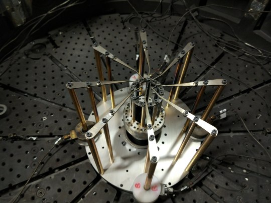
The beauty of laser cutting is that components become disposable. I’d expected this to be completely destroyed after the shot, but actually it’s only a little burnt:
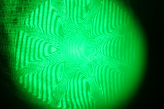
I managed to get seven imaging diagnostics onto this shot, which was a lot of work, but the results look very nice:
You can see eight converging streams of plasma, about to collide at the centre of the image. The stripy pattern is due to interference fringes - this diagnostic is a Mach Zehnder imaging interferometer, and the fringes are bent in regions where there is plasma.
The data from today’s experiment reproduces our previous experiments, which suggests that this new platform should allow us to make a turbulent plasma column. The next step is to repeat the experiment to look at later times (when the streams have arrived at the centre of the image) and determine when turbulence sets in. Then we need to get even more diagnostics and see what we can learn!
2 notes
·
View notes
Text
Back in the lab, with shiny new hardware
Since handing in my PHD thesis in March, I've been working as a Research Assistant (Post Doc) in MAGPIE. At first I was helping out others with their experiments and getting back into the flow of things, but yesterday I had the chance to try out some new hardware I'd made to do magnetic reconnection experiments.
The new hardware is significantly more flexible than the the previous version, and allows us to study reconnection in a variety of new regimes. But the important first test was whether it could reproduce the results in my thesis, and so I started with my standard configuration. The parts were mostly laser cut from 1.5 mm thick stainless steel, with the rest machined from stainless steel.
The final assembly looks like this...

...and in the next few images I’ll show how this was put together.

This is the anode plate, and it’s made from three laser cut sheets bolted together. Sitting on the anode plate are two thin cylinders, which have disks glued to the top which each have 32 small holes in for the carbon rods. Everything is glued together with superglue, but to avoid using too much glue I apply it a small drop at a time with a 200 micron acupuncture needle.
The cylinders then can be rotated to get them aligned:

and the completed anode plate is then ready to go into the vacuum chamber. First, however, I need to install the cathode assembly.

This image is taken from inside the vacuum chamber. The central object is the cathode, and the disk surrounding it is the cathode. The electrical current (one million Amperes!) flows from the anode to the cathode through whatever we put in the way. You can also see the elliptical mirror in the centre of the image which we use for reflecting a laser beam to take pictures of the plasma.

The cathode posts are bolted onto the cathode. These are long, stainless steel rods that are thick enough not be destroyed when the MAGPIE current passes through them.

The anode assembly goes over these posts, and sits on the anode. The cathode posts go through the centre of the two cylinders on the cathode plate.

Now the top disks are attached, which also have 32 holes in each of them. I rotate the top disks so that the holes line up with the disks below, and then grab the carbon rods (aka pencil leads).

Each pencil lead is placed by hand, leaving some sticking out of the top.

The excess pencil lead is removed by applying a small amount of pressure with an acupuncture needle. This breaks the lead just where it meets the top disks, leaving nothing sticking out of the top of the arrays. Nice and neat.

The completed arrays from below, showing the cathode and anode sections.

The array is built leaning over the chamber. The knee pads are vital as I get older and my joints start to go. It requires a good amount of core strength to keep myself from tipping forwards whilst building an array!

Finally, we put the lid on the vacuum chamber and pump out the air, ready for an experiment. The array takes about an hour to build, and is destroyed in a few billionths of a second. We can take pictures of the plasma using an expanded laser beam, and this is some of the data from the shot this morning:

The dark and light fringes are caused by constructive and destructive interference of the laser beam, and the fringes shift wherever there is a large amount of plasma. You can find out more about this technique and the experiments I’ve been doing on MAGPIE in our recent paper (for free here, published in PRL) .
1 note
·
View note
Text
Writing a PhD thesis

A grandiose title page.
I finished writing my PhD thesis a few weeks ago. It sort of fizzled out at the end - lots of little, irritating tasks to do even after all the writing it done. Before I started writing, and as I was writing, I often looked for blog posts and other material on how to write a thesis, and so, whilst it’s still fresh in my mind, and in the hope that someone else may benefit or at least be entertained, here are my thoughts:
There seem to be two types of issues when writing a thesis, technical and actually writing it. The technical stuff is a bit drier, so I’ll leave the details of how I edited the text until the end. Spoiler alert - it involves a lot of latex and pythons.
Writing

Drawing images is fun and took up a lot of time.
I started writing in August, and came up with an outline of my thesis in the forms of section headings in chapters. Sergey (my advisor) and I discussed this layout and made some minor changes, but the biggest changes came during the writing process. Often, they were frustrating and set me back by weeks, as Sergey found a different, better way to present the arguments and data. I resented some of this ‘extra’ work at the time, but it definitely made the thesis better overall.
Sergey’s particular trick, which I learned and then began to apply in advance, is to go from a narrative format (I did this experiment, then this experiment, then this experiment) to a textbook format (we know these things, and these things, and these things). This usually means taking data and presenting it in figures in contrast to other data. The text then discusses the similarities and differences. If this seems obvious and straightforwards, then you’re well on the path to being a good scientist! To me it was difficult, because it was only after writing the narrative version that I began to spot the similarities and difference between different data sets.
I didn’t write the chapters in order. On Sergey’s advice, I started with a description of the diagnostics I used, before going on to write about the results, then a discussion of the results, followed by the conclusion. I went then back to write the preliminary work, only including what I needed to buttress the rest of the thesis, before finishing off by writing the introduction and theory section.
I would usually try and make all of the figures I needed as I went along, in contrast to others who have told me they made all the figures they wanted on Monday and then spent the rest of the week writing about them. My problem is that as I wrote I would usually change the figures, and then have to go back and revise the old ones, and so writing about the figures as I went along allowed me to spot these necessary changes and implement them quickly.
I never wrote at home. An office environment is an excellent place to focus, and aside from one attempt to write half a chapter on the Oxford Tube as it careened around some side roads, avoiding an accident on the M40, I rarely wrote outside of an office. Without a mouse and a large screen it’s difficult to do the drawings I need in Illustrator, and without the drawings I have nothing to write about.
For the first four months I had trouble focusing, with interruptions to help in the lab, preparing for conferences and spending too much time reading the news. It took four months therefore to write three chapters out of seven. I returned from my Christmas break and surveyed the path ahead of me. My funding runs out on March 1st, and I have four chapters to write in two months. Shit.

Look at that death stare - Sibelius probably wrote a thesis at some point. By fi:Daniel Nyblin (1856–1923) - What We Hear in Music, Anne S. Faulkner, Victor Talking Machine Co., 1913., Public Domain
So I got serious. To drown out the noise I made long playlists of symphonic music (mostly Sibelius and Bruckner) which I would listen to without pause. At lunch I’d eat at my desk, watching cartoons online. I worked a strict 8:15 am to 5 pm for six weeks, bouldering three nights a week and slightly alarming my office mates and colleagues. In six days I had first drafts of three chapters, and set my sights on the final one. Sergey was slightly overwhelmed by the amount of work I was asking him to look through, and initially just skimmed through to look at the figures, which as you are gathering, are a major part of my work.
I began to relax and enjoy writing again, but I decided to keep the pressure on and finish as soon as possible so that I didn’t have to think about it any more. I was almost entirely done by 24th Jan, eighteen days after I got back to work. All that was left was a few days of ensuring copyright notices were appended, checking spelling in the bibliography and writing the acknowledgements.
Writing a thesis was a lot harder than I had anticipated. Initially, I thought that it would be fun or at least tolerable, and the fact that everyone else I had spoken to thought otherwise just indicated they didn’t have the right attitude. This was spectacularly naive, as I began to fully appreciate within the first month, where I would find myself drinking more and more low quality espresso in a desperate attempt to convert caffeine into words. I can’t really think of a way to make the experience more pleasant - certainly several people I’ve spoken to have had the same pattern of taking ages on the first few chapters and finishing up the last few very quickly, so perhaps that’s a consolation to bear in mind.
Technical Stuff
I wrote my thesis in Latex, one file per chapter, using includes. This means quicker compile times as you only need to compile each chapter at any time. I used Daniel Wagner’s template to ensure my margins etc. were compliant, and I chose Palatino as a font so that my math text matched nicely. I used one sentence per line to make error finding easier, and this made it straightforwards to use git to manage my thesis (private repo on github). Having version control like git was really useful, especially when reworking large parts of the text.
Figures were done using Illustrator, with one file per chapter and using artboards the width of my text. Latex can include specific pages of a PDF as figures, so I produced one PDF per chapter. Figures with data were done solely in python with matplotlib, and I had several long jupyter notebooks with all the necessary code. These figures were usually saved as PDFs unless PNG gave a drastically smaller filesize. Matplotlib was set to output figures the width of the text, which meant that I could specific eg. size 10 font and know it would exactly match that in the text.

Landscape triptych - to get the best viewing side, this fills an entire A4 page.
I spent a while writing a neat script to handle figures that fill entire landscape page. The latex file can either produce a print version, in which the figure is rotated onto a portrait page, or a digital version in which the page is rotated (a lot easier for reading on a screen!).
I took a while playing with Biblatex to get [Surname, YEAR] as the citation key, which was DEFINITELY WORTH IT. I also defined plenty of macros for things like x=X mm or JxB which kept cropping up. If I’d done this earlier on I would’ve saved a lot of time.
I definitely learned a lot whilst writing this thesis about Latex, Illustrator, Python and Matplotlib. Looking back there are quite a few things I’d do differently, but making those mistakes was part of the process and probably character building or some tosh like that.
I’m not submitting my thesis for another few weeks as I’d stop being a student and lose my lab insurance before starting my post doc in March, so for now I just help out in the lab and pretend that I’m a post doc already.
0 notes
Text
The Aurora and Magnetic Reconnection

By Ximonic (Simo Räsänen) (Own work) [CC BY-SA 3.0], via Wikimedia Commons
The Aurora is one of the most beautiful phenomena in the solar system, and it is intrinsically linked to an elegant and ubiquitous process called Magnetic Reconnection. In this blog post I will describe magnetic reconnection, and discuss how it creates the Aurora. I'll then show how we can do magnetic reconnection experiments on MAGPIE, and some of the work so far.

Magnetic reconnection occurs everywhere in the universe where magnetic fields meet, which is practically everywhere in the universe. Magnetic fields are embedded inside plasma, like string draped in thick treacles, and so as a plasma moves, the field lines are dragged along, sometimes becoming twisted and tangled. Unlike string, magnetic field lines have a clear direction, and when lines with opposite directions meet, magnetic reconnection occurs.
In magnetic reconnection, the oppositely directed field lines annihilate each other, converting the magnetic energy into heat and accelerating the particles in the plasma. The magnetic field lines reattach so that there are no loose ends - this is a topological change to the field, and it is profoundly important. This change in the magnetic field structure alters how the plasma can flow, because the plasma particles plasma move mostly along field lines.

By NASA Goddard Space Flight Center - Flickr: Magnificent CME Erupts on the Sun - August 31, CC BY 2.0
How does magnetic reconnection cause the Aurora? The Aurora begins on the surface of the sun, where vast, twisting arches of plasma known as solar flares are formed. The arches rise buoyantly, like flames, and as they do so the magnetic field lines within them are stretched until the field lines at the base are oppositely directed. Magnetic reconnection snips off the field lines attaching the solar flare to the sun, suddenly launching the solar flare out into space as a blob of plasma. These blobs are known as Coronal Mass Ejections, and they move out through the solar system at speeds of thousands of kilometres a second.

By NASA, Public Domain
Occasionally a Coronal Mass Ejection collides with the Earth. The Earth is protected from this searing ball of plasma by the magnetosphere, the magnetic field produced by the Earth's core. The magnetosphere is one of the many things that most people are unaware they should be grateful for, but fortunately the magnetosphere insensitive to ingratitude. The magnetic field of the coronal mass ejection and the magnetosphere interact, undergoing further magnetic reconnection, and the coronal mass ejection flows around the Earth. As it flows around, it drags with it the Earth's magnetic field, elongating it into a long tail the stretched behind the Earth.

Reconnection occurs in the red regions. The Earth is the blue dot. By NASA, Public domain, via Wikimedia Commons
This long tail also undergoes magnetic reconnection as the stretched field lines are brought into contact. Magnetic reconnection heats and accelerated the particles in the plasma here, and the particles speed back towards to Earth. These fast move particles strike the Earth's atmosphere at the poles, where most of the field lines originate, and cause the atmosphere glow with the characteristic green and red of the Aurora.
So to get an Aurora, we've had to invoke magnetic reconnection at least three times - firstly to pinch off a solar flare from the Sun an accelerate it towards Earth, secondly when the coronal mass ejection first hits the Earth, and finally behind the Earth to accelerate the particles to the poles and hence cause the atmosphere to glow.
In MAGPIE, we can generate streams of plasma that have embedded magnetic fields. By allowing two streams in which the fields are oppositely directed, we can trigger magnetic reconnection. We generate the streams using an 'exploding' wire array - a cylindrical shell made of thin rods or wires surrounds a thick central conductor. A large current from the MAGPIE generator passes up through the thin wires, turning them into plasma. The current returns to ground through the thick central conductor, which produces a large magnetic field that pushes the plasma outwards in every direction. The large magnetic field is embedded in the plasma, so as the plasma flows outwards it carries a magnetic field with it.

View of two exploding wire arrays from above. Light blue arrows indicate plasma streams, and magnetic reconnection takes place in the red region.
We place two of these exploding wire arrays side by side, so that the flows meet half way between them, and magnetic reconnection occurs. By choosing the material that the wires are made out of, we can change how fast the flows are and how the magnetic reconnection process takes place.
To study magnetic reconnection, it would be nice to observe the shape of the magnetic field lines, but this is difficult in our experiment. Instead we study how the plasma responds to the magnetic energy being released - it heats up and accelerates. Hot plasmas emit light just like a hot piece of metal does, and using a camera with a very fast exposure (five billionths of a second!) we can make movies of how the plasma responds. We can back this up by measuring the temperature and velocity of the plasma, as well as maps of the density. Our new Faraday rotation diagnostic allows us to measure magnetic fields and confirm that the magnetic fields are annihilated when they meet. This combination of qualitative and quantitative diagnostics allow us to make direct comparisons with theory and simulations.

An image take with a 5 ns exposure on a recent MAGPIE experiment, The bright regions are streams of plasma flowing towards each other. When they collide, magnetic reconnection should occur.
I'm just wrapping up a long experimental run on MAGPIE studying magnetic reconnection in carbon plasmas. Carbon is a interesting material to us because it appears to give plasmas which are hotter and carry larger magnetic fields than other materials. I won't write about what we've found until we've had a chance to analyse the data and prepare it for publication, but I hope to write more about some of the theoretical foundations of magnetic reconnection in a blog post soon.
#my work#experimental physics#plasma#thomson scattering#magnetic reconnection#aurora#coronal mass ejection#solar flares
0 notes
Text
Making Magnets!
My colleague Guy Burdiak has been working on making magnets for MAGPIE since I arrived at Imperial College, and yesterday I had a chance to help him out with the final winding process.

Adding magnetic fields to plasma physics experiments can fundamentally alter how the plasma responds. This is because plasmas are made from charged particles which are strongly affected by electromagnetic forces. To add a large magnetic field to our experiments on MAGPIE, Guy designed a magnetic coil made from a spiral of copper ribbon wrapped around a stainless steel bobbin. Using a separate capacitor bank, a large electric current (~5 kA) will pass through the copper ribbon, creating a magnetic field of around 10 T.

youtube
The machinery to wind the coil is a work of art. The copper ribbon must be wound on under considerable tension using a stepper motor, using about weight of a small human, and this tension must be continuously monitored (using, quite neatly, the force meters from a bathroom scale...).

At the same time as winding on the copper, a layer of paper dipped in epoxy is wrapped between the copper layers to provide electrical insulation. This gloopy mixture is made up from two separate fluids, one labelled corrosive, and the other toxic. Lovely!

New epoxy is constantly poured over the bobbin to ensure it permeates the entire coil. The epoxy is an exothermic mixture that gets quiet hot, and it stinks of ammonia. The entire coil winding process took about five hours, so you can imagine how enjoyable that was.
youtube
After all of the copper is wound on, Guy wrapped twelve layers of epoxy impregnated Kevlar over the top. The forces on the magnet when a large current passes through it are phenomenal, equivalent to around 30 tonnes, and these magnets have a tendency to explode. The Kevlar is intended to stop that from happening, but we have no idea if it works yet. My advisor Sergey is in the background, keeping the Kevlar in line as it runs through under tension.

Magnetic fields don’t move instantaneously, and they take some time to permeate through metallic objects. To make sure the magnetic field has fully permeated our experimental setup before the experiment starts, the capacitor bank must deliver a large current for a long time. In MAGPIE, that means milliseconds - quiet short, but still ten thousand times longer than the experimental time scale! This means the capacitor bank must be able to contain a lot of energy to keep that current flowing, and it turns out that it has almost as much energy stored as all the capacitor banks in MAGPIE!
1 note
·
View note
Text
The Evolution of an Experiment
Experiments on MAGPIE are expensive in terms of time and equipment - at best we can achieve one experiment a day - we really want to be sure a design will work before we put that much effort in! We use computer aided design (CAD) software (Solidworks) to make 3D models of new hardware, which we can then position inside a model of the vacuum chamber to check what we’ll be able to see from outside.

CAD drawing of an experimental load on MAGPIE, shown as a cut away section. This load was described in an earlier blog post - after two shots we’ve never returned to it...
Once we’re happy with the models, they can be converted to scale drawings which the Mechanical Workshop at the Physics Department use to manufacture the hardware. The workshop employs skilled machinists who work out the best way to make out whatever our latest crazy idea is, and they’re very patient with us. It can take around a month for a component to be machined due to the high demand on the workshop, and we usually don’t get spares of most parts.

Mechanical drawing of a single part for our ‘Horizontal Array’ experiments.
This hardware is then assembled in the chamber and used in a shot on MAGPIE. When things are subjected to million ampere electrical pulses they tend to behave in unpredictable ways, and things often go quite wrong.

Broken glass (top left) fills the chamber after this load (bottom right) hurls shards of brass rod in every direction. A vacuum window was broken, which caused the vacuum chamber to return to atmospheric pressure rather quickly, with a terrifying screech. This is the Mk I - the Mk II didn’t cause any permanent damage, but still didn’t work properly. The Mk III is under construction at the moment.
At this stage it’s back to the drawing board, which can mean a long time before the next iteration can be tested - there’s a week of redesign, four weeks in the workshop and a few more waiting for time on MAGPIE to available for testing. We try as hard as possible to ensure our experiments work before we actually try them, but one of the exciting parts of plasma physics is how unpredictable it is.
One recent innovation we’ve been making use of is laser cutting:
youtube
Video by George Swadling
Here, a jet of pure oxygen flows over a sheet of metal whilst an intense laser is focused down to a small point. The laser heats a thin sheet of metal and it burns rapidly in the oxygen jet, cutting straight through the sheet. The laser head is computer controlled and can move rapidly, so it can cut complicated patterns out very quickly using instructions from a computer file. The turn around time for laser cuts parts is often less than a day, and we can lots of copies made, or versions with slight differences so we can compare which works best.
I’ve designed several loads using laser cut hardware now, and it requires a bit of creative thinking to work out how to use on thin sheets of metal and connecting rods. By far the oddest looking thing I’ve designed is an attempt to rotate an existing experiment by 90′ to improve diagnostic access:

This hasn’t been built yet, but doubtless it too will need several months of redesign, tweaks and polishing before we can start doing science with it. I really enjoy designing and testing the unusual concepts we’re coming up with at MAGPIE, so I’ll be having fun regardless of whether it works or not!
#my work#magpie#pulsed power#cad software#solidworks#laser cutting#vacuum chambers#hyper-ballistic debris#experimental physics
1 note
·
View note
Text
More Than Just a Thermometer
In my last blog post I discussed measuring the temperature of a plasma. I talked about firing an intense laser into the plasma and looking at the light that is reflected off the plasma using a spectrometer. A spectrometer measures the spectrum (think ‘colour’) of the reflected light, and from the range of wavelengths in the spectrum we can deduce the temperature of the plasma.
The description I gave last time is appropriate when the wavelength of the laser light is smaller than the shortest distance over which the plasma can respond to electric fields. That probably doesn’t make much sense, so consider an analogy.

By Fæ CC BY-SA 3.0 via Wikimedia Commons
Think about a large, crowded street. If you focus on one person, their motion seems random, constantly stopping and changing direction, without a clear purpose. If you broaden your focus a little bit, you see more people - maybe couples walking together, or a group of friends or a coach tour. These groups act collectively, and our individual person must step out of the way or squeeze past other individuals and groups - this explains the odd behaviour that we puzzled over when we could only see one person. On an even larger scale, we see flows of people, up and down the street, with sinks and sources at shop doorways or side streets. At this level, the behaviour of the individuals on the street is unimportant - we can say the behaviour of the crowd is due to ‘collective motion’ which doesn’t necessarily look like the random, individual motion on smaller scales.
Plasmas are similar. On different length scales, different processes are important. In a plasma there is a fundamental length scale called the Debye length, which is the distance over which electric fields are reduced to zero by the collective motion of the charged particles in the plasma. For reflected light of wavelengths shorter than the Debye length, the light reveals information on the individual motion of charged particles. At wavelengths longer than the Debye length we get information on the collective motion of the particles.
I’ve already discussed the result due to individual motion measured by a short wavelength laser in my previous blog post. The light, which is initially all at one wavelength, becomes smeared out by the Doppler shift as all the electrons are moving randomly towards or away from the laser. It is possible to deduce the electron temperature by the range of wavelengths recorded because the temperature is directly linked to the random velocities of the electrons.
More interestingly, we can consider the result for collective motion, using a longer wavelength laser. For almost all of the plasmas we study on MAGPIE the Debye length is about the same as the wavelength of the laser we have, so we are on the boundary between measuring collective and individual motion. What sorts of collective motion are there in a plasma? Despite the convincing analogy above, I don’t expect you to believe there are couples and tour groups inside a plasma, but instead we have sound waves. A ‘wave’ here means the physicists’ short hand for a propagating disturbance, and sound waves are propagating disturbances of density and pressure.
Sound waves in a plasma are similar to sound waves in air - they move at a fixed speed determined by the temperature of the air and the mass of the air molecules, and inside a sound waves the particles oscillate backwards and forwards without an bulk motion. Sound waves can exist inside a moving plasma just as they can inside moving air (you can, afterall, have a conversation in a car). When our laser reflects off particles which are being oscillated by a sound wave, it will see an equal number moving away from the laser as towards - this gives rise to two peaks in the spectrum of the reflected light, space evenly on either side of the original wavelength. The two peaks correspond to the reflected light being Doppler shifted to both higher and lower frequencies by the particles moving towards and away from the laser.
Because the velocity of the sound waves is known and depends only on the plasma temperature and the mass of the charged particles, we can determine the plasma temperature from the frequencies at which the peaks occur. To be more precise, the sound speed in a plasma depends on the electron temperature but the mass of the ions - as electrons and ions in a plasma can have quite different temperatures this is quite interesting.

Two peaks due to sound waves in a carbon plasma, measured on MAGPIE. The two peaks are at different heights due to an effect called Electron Landau Damping, which I can’t think how to explain right now - this probably means I don’t understand it. Fortunately for us, it turns out to be a useful measure of another important plasma property, the relative speed of the electrons with respect to the ions.

By pam fray CC BY-SA 2.0, via Wikimedia Commons
In a plasma with a magnetic field, there is yet another type of wave. This arises because charged particles spiral around magnetic field lines, a concept I discussed in one of my first blog posts. Think about a Merry-go-round with someone on every horse.. As the merry-g-round spins, some of the people are coming directly towards you, some directly away, and the rest are going left or right or some mix of all of these. Because you are looking from the side, there appear to be more people heading directly towards or away from you than there are going left or right.
In a plasma, if you look at right angles to the magnetic field line, you will analogously see more charged particles moving directly towards or away from you, and so light reflected from a plasma with a magnetic field will have peaks corresponding to the collective motions of the particles [1].

Spectrum of light scattered from a plasma with magnetised electrons. Own work. The tall peaks due to the sound waves are in the middle - the smaller peaks out to the sides are due to the magnetic field.
In fact, you don’t just see two peaks, but huge range of peaks. I can’t explain why there are so many using the basic picture I’ve outlined above. I would have to mutter something about non-linearity and harmonics, but that wouldn’t convince me either. If I find a good explanation I’ll write a blog post about it - at the moment I simply rely on the mathematics.

Data from Evans et al. [2] - peaks due to collective motion of the plasma’s electrons in a magnetic field.
However, I can say that the peaks all equally spaced by a wavelength that depends only on the magnetic field and the mass of the electron. As such, this is a remarkably sensitive and precise technique for measured magnetic fields, but the last time I can find that it was done experimentally was in 1970 [2]. I’d very much like to try this experiment in MAGPIE, but it requires very precise alignment of the laser and the spectrometer, so it may elude us. Congratulations on getting to the end of this blog post - have some references:
[1] Froula, D., Luhmann, N., Sheffield, J., & Glenzer, S. (2011). Plasma scattering of electromagnetic radiation.
[2] Evans, D. E., & Caolan, P. G. (1970). Measurement of magnetic field in a laboratory plasma by Thompson scattering of laser light. Physical Review Letters, 25(23), 1605–1608.
3 notes
·
View notes
Text
The Million Degree Thermometer
Plasmas tend to be quite hot. This is because they consist of electrons and ions, which are strongly attracted to each other. To over come this attraction, the system must have sufficient kinetic energy, or more loosely, the particles need to be going ‘fast enough’. In my work, temperature is simply a measure of how fast, on average, the particles in a system are going. It’s a measure of the disordered, chaotic speeds in a system. An analogy is a cold, fast flowing river - all the particles are moving quickly in one direction, so the kinetic energy is large, but the temperature or thermal energy is still not very high. If this river hits a dam and slows down, most of that directed kinetic energy will go into heating up the water - the particles will move more randomly, and the temperature is now higher, but the water doesn’t flow because the speeds are all in random directions.
So how hot is a plasma? It’s possible to quickly calculate a temperature for a simple system of just one electron and one proton that are attracted to each other but kept apart by their large thermal energy. This tends to overestimate the temperature necessary for a plasma, but roughly 10,000 C is about when plasmas begin to form. At this temperature, the difference between degrees Kelvin and degrees Celsius is negligible - if you’re a fan of Fahrenheit, multiply by two and you won’t be far wrong.
This is quite hot, and sticking a mercury thermometer in and trying to measure off the scale isn’t really practical - the plasma would most likely loose all its energy to the thermometer, and even if it didn’t, the mercury would boil, evaporate and ionise and form a plasma that would leave you back where you started.

"Wiki lizards" by Arno / Coen Licensed under CC BY-SA 3.0
You could try one of those nifty infra-red cameras, beloved of spy films and Federal agents trying to spot grow rooms. These work by detecting black-body radiation, the concept that an object at a certain temperature emits light of specific frequencies (if you like, think ‘colour’ for frequency). Our plasma is so hot that it doesn’t glow in the infra-red, or even orange or white like a hot poker, but instead it glows with x-ray light, invisible to humans. Unfortunately, this isn’t a very precise diagnostic, as if different bits of our plasma are at different temperatures then we will just get a mish-mash of light at different frequencies.

Credit: Fábio Pozzebom/ABr Licensed under CC BY 3.0
No, what we need is something more like a speed camera, specifically a Radar gun. These fire out radar waves that bounce off the speeding object and back to the source. The waves coming back are at a different frequency than the waves that were emitted - you’re probably familiar with this ‘Doppler shift’ from ambulances speeding by with their sirens on. When the ambulance is coming towards you the pitch is higher, and when moving away from you it sounds like a lower pitch. The same effect can happen with all waves, including light, and so we should be able to bounce waves off individual electrons and ions and see how fast they are going.
At this point, you might reasonably object that a car is somewhat bigger than an electron and the whole plan probably won’t work with a standard Radar gun. You’re quite right - what we really need is a very, very powerful light source, like a laser, that we can focus down to a tiny spot so that even though the chances of any of the light bouncing off an electron is quite small, we have such a high intensity to start with that the bounced (physicists say ‘scattered’) light is still detectable. Additionally, we are not bouncing light off one electron, but a blob of plasma containing billions upon billions of electrons, all of which bounce light back at us so that we can collect a measurable amount in our detectors.
What do we expect to see? If all the electrons are going in the same direction at the same speed, the light we collect will simply be at a slightly different frequency to the light we emitted. In reality, all the electrons are moving in different directions at different speeds - that’s what having a temperature means, random speeds in random directions. So we’ll collect light at a range of frequencies, and by looking at the range we have we can estimate the temperature of the plasma. This technique is called Thomson Scattering, and it’s widely used in plasma physics.

This plasma is around one million degrees Celsius. The laser we fired into the plasma has a well defined frequency - the light we collect has a broader range of frequencies. The analysis here is far from straightforwards - a simple model would just have a broader peak, and not two peaks of different heights.
In practice, when we examine the frequencies of the light we’ve collected, we might be quite surprised that it doesn’t follow the simple model above. This is because the plasma is made of charged particles, and the light is a tangle of electric and magnetic fields that push and pull the plasma around and are wiggled and wobbled in return. I’ll address this in my next blog post.
1 note
·
View note
Text
Making plasma from pencil leads
I’ve already done some preliminary experiments on passing a large electrical current through some pencil leads to turn them into a carbon plasma - I described the physics involved in my last blog post. Recently I spent three weeks on more experiments on MAGPIE, and the results have been really interesting.

Array hardware loaded in the vacuum chamber, ready for a shot.
We used a neat trick developed on MAGPIE to flip the array by 90′ so that all of the pencils leads lie horizontally instead of standing vertically [1]. This requires a bit of extra hardware to make sure the electric current flows equally through each of the pencil leads, but the pay off is better diagnostic access - we can look at the plasma from more directions at the same time, and so hopefully we can measure more of the plasma’s properties.
The new hardware has been laser cut for us by the Physics Workshop. They use a laser that is focused on a thin sheet of steel to cut out detailed shapes with astonishing precision. It’s very quick and easy, so they can make lots of identical copies of the parts, which is quite useful, because here’s what they look like after a million Amps have passed by:

Array hardware post-shot, smashed to bits
During the shots, everything seems to be going as planned - supersonic jets of carbon plasma smash into each other at the centre of the array, forming a very hot dense plasma. We can measure the density using interferometry, giving stunning images like this:

Interferogram looking at colliding jets of carbon plasma
I’ve spent the last few days writing some code to interpret the Thomson Scattering spectrum, which should yield the temperature of the plasma and how fast it’s going. Initial results give us around 550 eV, which is equivalent to 6 million degrees Celcius.
My experimental run might be over for now, but the work of interpreting the data has just begun. I’ll write more soon on how we use the Thomson Scattering spectrum to work out so much about the plasma.
I should stress that the work we do on MAGPIE requires a large team of people, and I’m indebted to (in no particular order) Lee, Thomas, Guy, George, Jian Wu and Qingguo for their help.
[1] Swadling, G.F.; Hall, G.N.; Lebedev, S.V.; Burdiak, G.C.; Suzuki-Vidal, F.; de Grouchy, P.; Suttle, L.; Bennett, M.; Sheng, L., "Commissioning of a Rotated Wire Array Configuration for Improved Diagnostic Access (October 2014)," Plasma Science, IEEE Transactions on , vol.PP, no.99, pp.1,1 doi: 10.1109/TPS.2015.2388863
#plasma#pencil leads#carbon#supersonic#interferometry#my work#experimental physics#who reads all the way to the end of a list of tags
0 notes
Text
Firing MAGPIE part 2
Part 2 follows on from my previous post about how the intense electromagnetic pulse is generated. In this post I discuss the physics of what occurs inside the chamber when that pulse passes through the load.

Drawing of MAGPIE. This whole posts takes place inside (5).
Downstairs, my finger is still pressed to the button that started the whole experiment. It’s only been milliseconds, and ‘Firing!’ still hangs in the air: so little time has passed that the word is only a few metres away. Four huge banks of capacitors have discharged a pulse of electricity which has been compressed in time and focused in space, rushing upwards through a squat cylindrical pipe filled with water towards the metal chamber held in a powerful vacuum.

<;/div>
The chamber, a metal cylinder 80 cm across, shown here without the lid that seals it and allows us to pump all of the air out. The load is in the centre - the very small central circle is the diameter of the circle of pencil leads.
Inside the chamber, the valve has slammed shut, sealing the chamber closed, but it’s peaceful, with no sign of what’s to come - the electrical pulse is moving upwards at the speed of light, and there’s nothing that can go faster to warn of the powerful force approaching.
At the neck of the MITL, the narrowest gap between the inner cylinder and the outer, straining at the limits of its design, electrons flung across and whipped around and back, the current pulse enters through a slender stalk a few centimetres across. The metal surfaces heat, blowing off grease and oil in puffs of bright plasma, scouring our fingerprints from the tarnished metal and leaving a seething, roiling plasma around the cathode.
The current continues upwards, searching for a path back to the Earth, electrons driven onwards by the relentless, rising voltage. Above the cathode are eight carbon rods, the thinnest pencil leads you can buy, standing upright, arranged like a stone circle.

The electric current surges up through them, electrons colliding with the atoms in their graphite lattice, smashing them from their rightful places, joggling and jostling the atoms as the temperature rises and then the lattice can’t hold back, there’s a crack and an explosion, electric and elemental, the rods no longer solid, but liquid and vapour, expanding slothfully into the vacuum [1].

The electrons are flummoxed and in flux, their easy path destroyed by their own unstoppable eagerness, and now they find it far harder to push through the liquid core, so they head to the surface, the outside of the carbon columns, smashing into atoms along the way and liberating more electrons for the mayhem. The outside of the expanding-vapour-cloud-that-was-once-a-solid-carbon-rod heats and becomes a plasma, glowing, twisting, flowing, conducting and hence current carrying, a soup of electrons and ions in which the electrons can flow freely, electromagnetically active and still following the voltage wave dragging them upwards. This plasma is a corona, a seething crown surrounding the cold vapour-liquid core. [2]

An electric current always generates a magnetic field, and each of the eight rods is encircled by rings of field lines, pushing the plasma back inwards and pinching it down. As the electric current increases, the plasma gets hotter, and its own pressure builds, pushing back against the magnetic prison until it can break free, and the plasma makes a dash for it towards the centre of the circle of rods.

2D simulations of eight-wire arrays , showing magnetic field lines being dragged inwards by the plasma (right frame is later in time than the left frame) Shading is mass density [3].
Back at the rods, the hot plasma surrounding the cold cores is constantly renewed by wayward electrons stumbling into the liquid-vapour mix and ionising a stray atom here and there, a new recruit for the plasma corona that constantly flow inwards like smoke blown from a fire.
Dragging electric current along as it flows, the plasma shifts and changes the magnetic field, opening up the tight circles of field around each rod and morphing it so that more plasma is thrust inwards, accelerated up to massive speeds and hurled towards the centre. Right there, on the axis, eight streams of supersonic plasma meet and collide. [3]

In the centre, a maelstrom of seething turbulent plasma has developed where the eight streams have collided and mixed, forming a shock that slowly expands outwards, a glowing pillar with a rippling surface, taking the speedy plasma and slowing it, exchanging velocity for temperature, compressing the plasma back to a high density so that it glows like a poker in a fire.

There’s precarious balance of heating and cooling here, like leaving a window open with the central heating on - the shock takes the fast plasma and makes it into hot plasma, creating a constantly renewed hot skin to the central column. The plasma loses heat by giving off light, not in the infra-red like animals do, but it’s so hot that the plasma glows with x-rays and ultraviolet light. Too much cooling and the column will collapse, unable to withstand the barrage from the new plasma hit its surface [4]. For now, the balance is just right and our column of plasma glows and grows, giving off invisible light that is captured by our cameras.

An extreme ultra-violet (XUV) image of the plasma. Just like an infra-red camera can see light invisible to the human eye, so can out XUV camera, which show not only the eight jets of plasma colliding with the bright central column, but eight additional spokes between the jets, hinting at additional standing shocks.
A delay circuit downstairs has been waiting patiently for its big moment, and here it comes - with a pulse of light, it signals a laser above it to fire, streaking the chamber with bright green light that distorts and deflects as it passes through the plasma on its way to a camera. The laser pulse is short, and the plasma barely moves in the billionth of a second it takes to pass, leaving a bright green snapshot of a single instant in time.

Laser shadowgraphy, this time from the side. You can't see all eight rods because each rod hides one behind it.
By now, the experiment is over. The surge of electrical current begins to abate, the delicate balance is lost and the glowing column of plasma dims and then winks out, the rods cool to a roiling carbon fog that drifts and coats the inside of the vacuum chamber, and downstairs we hear the sharp metallic bang that signifies that something has just happened.
It’ll be another few minutes of check oscilloscope screens and cameras before we know if anything worked, several months of analysis before we understand what’s going on and maybe a year before a paper can be published to let the world know what happened in those scant few billionths of a second here in our machine, a dream of a machine, nestled in a windowless basement two floors under the ground, the dark oil slowly churning as it settles down after its brief exertion.
[1] Aleksandrov, V. V, et al. (2001). Dynamics of Heterogeneous Liners. Plasma Physics Reports, 27(2), 89–109.
[2] Lebedev, S. V et al. (2001). Plasma formation and the implosion phase of wire array z -pinch experiments. Laser and Particle Beams, 19, 355–376.
[3] Martin, M. R. et al. 2010). The role of magnetic field in the transition to streaming ablation in wire arrays. Physics of Plasmas, 17(5), 052706. doi:10.1063/1.3392288
[4] Bott, S. C. et al. (2009). Study of the effect of current rise time on the formation of the precursor column in cylindrical wire array Z pinches at 1 MA. Physics of Plasmas, 16(7), 072701. doi:10.1063/1.3159864
#magpie#plasma#my work#xuv#shadowgraphy#lasers#pulsed power#electrical explosions#heterogenous liners#new tags for tumblr#formatted bibliography
0 notes
Text
Firing MAGPIE, part 1

The load, an elegant sculpture hours in the making, nanoseconds to destroy.
We’ve been working on it for days, probably. The load is small, no larger than a fist, an elegant sculpture of metal or carbon, nestled in the centre of a steel cylinder, surrounded by thick glass windows. It might have wires thinner than a human hair, or a complex arrangement of foils, loops, cables and plates. We’ve surrounded it with glass and sheets of metal to deflect and absorb the destruction that will ensue. There are lasers pointed at it, through it, into it, from the side, and above, with lenses and apertures like the remnants of a camera strewn across the gleaming metal tables.

Turbo pumps bring the pressure in the chamber down by a factor of 10 million.
The steel chamber is pumped out by turbo molecular pumps, mini jet engines that bat air molecules down and out, stretching and thinning the air until you can’t call what’s left a gas, really, just a handful of particles bouncing off walls. The pumps work overnight, and by morning we’re ready. Everything has been checked and rechecked, numbers shouted across the lab, written down, checked again, argued over, references consulted, phone calls made, but here it is, we’ve done everything we can think of and if it goes wrong now, well, we’ll just have to do it again, and better.

Trigger units set to single shot mode - once they get a trigger signal, they will delay it and repeat it tens or hundreds of nanoseconds later to get the timing just right.
Press all the buttons, flashing red to a solid glow, ready to go, only one shot now, the tests are over, close the door and seal up the electronics, delicate and sensitive, shielded inside a box of steel from the electromagnetic maelstrom that will strike soon. Downstairs we go, lights off above, shouts upstairs to check no one’s there, unaware, sirens on, warning lights flashing, doors closed and ear protection donned. With a clunk, the power supplies start, two unassuming beige boxes with little dials and brightly coloured buttons, and digital displays the count upwards in synchrony as we watch.

A Marx bank, four metres tall and filled with fifty thousand litres of oil and a lot of electronics
Inside the four towering red tanks, charge trickles into the four Marx banks, regulated, counted, take one electron from this side, put it on that side, stored in capacitors, polished metal boxes stacked in four columns of six, with resistors full of pale blue liquid forming the arteries through which the charges move, the lot mired in deep brown oil that stirs slightly as the voltage rises. Minutes pass, and we count them in volts, calling out the potentials positive and negative, eyes scanning all the dials, the displays, the quivering needles. I am restless and nervous and the pressure in my head is rising in anticipation and I just want it to work so badly, but I’ve got to hold it back and keep a close watch, be a dispassionate scientist unconcerned by the days (weeks?) of preparation this moment embodies. Finally it’s ready, good to go, all set, and our nerves can’t take it any more either, so we thump red buttons that protect the power supplies from the inevitable electromagnetic backlash, and hit a small green blinking light nestled in amongst a tangle of wires. It’s labelled ‘MAGPIE GO BOOM’, and boy does it.

The MAGPIE trigger button

The Trigger Marx, a smaller Marx bank that triggers the larger Marx banks. What triggers the Trigger Marx? That is one of the deep mysteries.
To us, it’s over in an instant. To the machine, it takes a little longer. A pulse of voltage races upstairs, slamming a valve shut to protect the precious pumps perched behind, isolating the steel cylindrical chamber in which the everything plays out from the rest of the lab. Another signal streaks back downstairs, giving the all-clear, the time is near, counters starting, ticking, delaying, waiting for their moment, and at the back of the lab, in a brown box the size of a coffin the trigger bank sputters into life, first one spark, then two, three, four, the voltage building and racing down thick black cables towards the four looming red tanks.

A gas switch, not in a bank. We fill them with sulphur hexafluoride, a gas which is very resistant to electrical breakdown.
Inside the tanks, all is peaceful. The capacitors sit quietly, taking the strain of the huge voltage placed upon them, holding the positive charges away from the negative. The gas switches are silent, cylinders with brass domes, and the electric field is huge, and it rips electrons out of the metal and hurls them towards the opposite side, each trying to make their mark with a spark. But the gas is too thick, the electrons get nowhere, they collide with a fat molecule and lose their energy, and the roiling, boiling sea of evaporating electrons never makes it to the opposite shore.
But now the trigger signal has arrived, its long journey around the lab complete, and it smashes the tranquillity, gives the switches a smack with an electric hammer, shakes them up a bit, and it’s overwhelming, the electrons surge across the deepest switch, and as they go they light it up, the gas glows, current flows, negative connects to positive, and before you know it it’s got to the next switch up, the current rising, and that ones goes too, unstoppable now, building in power, a surge of electricity that breaks down all the gas in its path, and before you know it, twelve switches glowing, the voltage is a dozen times larger, and it can’t be contained any more, it’s got to get out, and it finds a way through a thick copper pipe that passes through the wall of the tank, encircled by plastic.

One of the pulse forming lines, metal pipes a metre in diameter, like coaxial cables but filled with deionised water.
It’s electromagnetic now, you see, not static charges and stale potentials but fields that skitter and skate across shiny surfaces, propagating past plastics, polarising, near the speed of light, fields that wobble themselves and each other, interfering, bouncing, reflecting, racing through a steel pipe a meter wide, filled with water that twists and turns, the molecules trying to align with the field that tears through them, but the water’s slow, too slow, and the wave will be past, long past by the time they’ve twisted into the right position, leaving the water dazed and confused, twisting aimlessly as dying wave echoes back and forth. But ahead there’s a wall, full stop, the wave slams on the brakes but can’t reflect, there’s too much voltage piling up behind it and it’s stuck.

The line gap trigger in all its glory. Screwdriver, buckets of oil and spare capacitors sold separately.
But not for long, for at the back of the lab, gurgling in its own vat of oil is another capacitor that’s been biding its time, waiting for its signal, and it’s got the go, gotta go, so it does, with a fizz and a pop, dumps the lot into four lines, identical lengths, voltage pulsing down, racing each other to the switches that are holding the four tidal surges of current separate. The switches are big, half a metre across, filled with gas (and plenty of it) that refuses to budge until it’s given a nudge, and then it goes, breaks down, glows, and there it is, the switch is closed, and the current rushes on.

The Vertical Transmission Line, where the four Marx banks discharge their electrical current so it can be deflected upwards to the experiment.
The four waves become one in a squat vertical pipe, steel still, three metres across, coaxial - it’s practical - and as the waves mingle and wash over each other they surge onwards, drawn upwards through the water. The walls close in, the gap narrows between the inner cylinder and the outer in the mighty MITL, magnetically insulating, voltage transmitting. The fields intensify as they’re crushed, and the forces are incredible, electrons ripped from the metal, trying to streak across the gap and spark, stop the show, but the current is intense and the magnetic field more so, and those errant electrons are whipped around and sent back the way they came. None cross, the MITL holds them off as it narrows, now half a metre, now a few centimetres across and here, at the breaking point, the current pulse enters the steel chamber in a silent, motionless vacuum and the experiment really begins.
To be continued.
0 notes
Text
Sparging for fun and profit
It's been a hard few months on MAGPIE. Constant component breakdown, electrical failures, maintenance periods and attempting to bring on-line some of the most complex diagnostics we've ever dreamed up have made progress slow and data scarce.

The charging barrel, full with transformer oil. Eight cables (not shown, they would attach to the brass cylinders at the top) take the two polarities (positive and negative voltages) to each of the four banks. The pneumatics are part of the safety system that only allows charging when all the doors are secured.
The latest failure was our charging barrel, a barrel of transformer oil full of bulky resistors, charging rails and pneumatics. When we started charging the Marx banks for a shot on Wednesday we heard an awful crackling wail coming from this barrel, and the voltage was leaking out of the Marxes like water through a sieve. In the darkness, we could see the tell-tale flicker of a coronal discharge, as streamers of ionised material sparked between conductors.
Not good. We scrubbed the oil, and left it to settle, but to no avail. Then this morning over tea, one of the senior researchers in the group suggesting 'sparging'. I'd never heard of this, and giggled. But apparently it's the process of bubbling an inert gas through a liquid to remove dissolved impurities, the idea being that our oil was contaminated with dissolved water. My advisor looked a little sceptical, but it seemed like an easy thing to test.
As a good scientist, I did a quick literature review, and turned up a paper from Sandia National Labs in 1999. Sandia are the big boys of pulsed power (high voltage, short time) engineering, so if they've tried this technique it must be legit. They even had the very relevant line:
"The component failures caused by poor oil performance were indistinguishable from normal Marx system failures that occur as components age. This may explain many random system faults previously attributed to component failure."
I showed the paper to Sergey and rushed downstairs to build a sparging unit.

Our 'oil torturer', filled with oil and ready for testing. The little glass window lets us see the sparks when the oil breaks down as high voltage is placed between the submerged brass electrodes.
We already had a test unit for seeing how good a batch of oil is at holding off high voltages. It's a little chamber with two brass balls inside, one grounded and the other charged by the dump barrel. With some of the contaminated oil from the charging barrel we could hold off 6.5 kV, which is pathetic.

Mk 1 Hare Industries Sparge-a-tron 9000, with ballast nut. It fits the bottom of the bucket perfectly.
I coiled up some plastic pipe into a spiral, cable tied it to a sheet of metal, added a big nut for ballast and got some vicious looking hypodermic needles we had lying around to puncture holes in it. By this point one of the postdocs had got in, and our enthusiasm was high. We filled a bucket with contaminated oil, turned on the nitrogen for half an hour and let it sparge away.

The oil bubbling merrily as nitrogen rushes through from the Sparge-a-tron underneath, dragging the dissolved water with it.
After this, we dumped the 'clean' oil back into the oil torturer and found it could hold off 30 kV, almost a five-fold improvement. Buoyed by success, we dropped the Hare Industries Sparge-a-tron 9000 (TM) into the bottom of the charging barrel, and left it bubbling away. The volume is far larger, but after 90 minutes of thorough sparging, we found the oil could hold off 27 kV, a remarkable improvement. We tested the charging barrel, and weird noises and lights were gone. Success.

Bubbles at the top of a Marx bank from the improved Hare Ind./SwadTech Mk 2 Sparge-a-tron 9000 (TM). My hand indicates the precarious position I'm balancing in.
Nitrogen is cheap as chips (£6 for a big bottle) so we built a large Sparge-a-tron that would fit inside a Marx bank out of a cable tray and some hefty nuts for ballast. We sunk that into the bottom of one bank and opened the bottle up. A huge rush of bubbles floated up through four metres of murky oil, driving a fast convection current and stirring the oil nicely. We'll leave it overnight and test the oil in the morning to see how much nitrogen we'll need to bring all the oil up to specification.
0 notes
Text
Shock waves for heating and compressing
Shocks are very important in physics and engineering. They occur whenever there are large pressures involved. In plasmas, we often have very large pressures, caused by magnetic fields or lasers. These pressures can be used to heat and compress matter to conditions not normally found on Earth. For example, we can recreate the conditions in the centre of a planet, or during a meteor impact. Or we can heat and compress matter to the conditions necessary for nuclear fusion.

An image of shock waves forming around a supersonic projectile. Licensed under Public domain via Wikimedia Commons
Shocks aren't a common occurrence in every day life. In a fluid, like the air or water, energy usually moves around in the form of sound waves. If the pressure increases locally, say by heating it a little or by speaking, a wave is set up that redistributes the excess pressure into the surroundings. When the pressure is too high, however, sound waves can no longer carry enough energy away, and a shock wave is occurs. A shock is a discontinuity (sudden sharp change) in the density and pressure of the fluid.
The actual mechanism for this is difficult to understand using fluid dynamics. This is because the shock front is very narrow, much smaller than the mean free path. The mean free path is the average distance a particle travels before hitting another particle. Fluid dynamics works by zooming out and assuming that particle collide frequently enough that we don't need to worry about individual particles. This is impossible on small scales, and worrying about individual particles is quite hard - there are billions and billions of them. This makes the physics of what happens inside the shock quite hard.
However, all is not lost. We can use the equations of fluid dynamics to work out the jump in the density and pressure because we know that mass, momentum and energy must be conserved - the amount of fluid flowing into the shock front must equal the amount flowing out, and the energy of the fluid flowing in must equal the energy in the fluid flowing out. This is a neat trick to avoid having to do hard physics, and it works very well indeed.
Shocks always compress and heat fluid - the density and pressure always goes up. Just by conserving mass, momentum and energy, it seems like it should be possible to have a shock wave that lowers the density and pressure. The reason this doesn't occur is due to thermodynamics. Effectively, we can convert the ordered kinetic energy of a flowing fluid into thermal energy using a shock front, but we can't convert random thermal energy into a ordered flow.

Three stages of plasma formation. This image looks down onto eight wires (grey cylinders). A current passes upwards through them, out of the screen. In the first stage, the current heats the wires, causing the surface to melt, boil and ionise into a plasma. The current also generates a huge magnetic field (100T) that whips the plasma inwards at supersonic velocities. These 'ablation flows' collide in the centre, and a shock front forms. The column of shock heated plasma slowly expands outwards, constantly fed by new material from the ablation flows colliding with the shock front.
We use shocks in MAGPIE to heat and compress plasma. First, we accelerate the plasma to supersonic speeds using a strong magnetic field. Then, we collide the plasma with other plasma flows coming in from different directions. Because the flows are supersonic, sound waves aren't fast enough to carry away the energy. A shock forms, heating and compressing the plasma. The shock wave begins to expand outwards as more plasma arrives and has its kinetic energy converted to thermal energy. The shock is very efficient at heating - the thermal energy of the material is close to what you'd expect from the kinetic energy of the flows, heating the plasma to around 10 million 'C. The density is at least four times larger than in the flows, a few times denser than air.

My often used image looking at the side of the wires (contrast with the diagram above looking from the top). The ablation streams are the wavy horizontal lines on the left and right, and the shock wave is the darker vertical line near the centre. The shocked plasma is the rippling column in the centre of the image.
Shocks are very useful for getting to the densities and temperatures we need to understand how to do nuclear fusion. They are quite destructive, however, and they can shred the plasma before it gets to the necessary conditions for fusion. It's better to add the energy slowly, and let sound waves distribute it evenly within the plasma. This takes a lot more energy, however, as slow heating allows some of the energy to escape. At MAGPIE, we don't have a lot of energy to play with, so we can cheat and use shock waves to get us to the densities and temperatures of a larger, more expensive machine, and still gain some insight into the relevant physics at these conditions.
0 notes
Text
Is the Lockheed Martin Fusion Reactor Actually New?
There's been a lot of buzz about a press release from Lockheed Martin about a fusion concept they've been working on. The press release says practically nothing, and the accompanying video says little more. What's incredible is that this not even a news - Lockheed Martin have been working on this for years, and even presented a far longer video almost two years ago at the Google run event 'Solve for X'.

Frame from the Lockheed Martin video showing a cylindrical vacuum vessel with a single coil supported by three posts.
A common narrative in technology these days is of radical new ideas that revolutionise the field. By playing into this narrative, companies can generate excitement for their product, and therefore revenue from their investors. In some fields, true innovation is easy to evaluate. AirBnB has the obvious advantage of running a hotel where you don't pay tax or conform to local health and safety laws. The cost savings are obvious. In nuclear fusion, it's quite hard to evaluate a proposal, and the real absence of information on Lockheed Martin's proposal makes it even harder.
Despite this, they give some hints away - surprisingly, the video from Solve for X actually has more information, which does make you wonder what the team has been doing for the last two years.
The Lockheed Martin design is a 'compact fusion reactor' with the following features:
Cylindrical vacuum vessel
Small vessel
High-Beta plasma
RF heating
The trouble is, none of these ideas are new.

MAST at CCFE in the UK, a 'spherical tokomak' with a cylindrical vacuum vessel.
MAST in the UK has used a cylindrical vacuum vessel for ages. Cylinders are easier to make than toroids, but unless you have a cylindrical plasma, they are not more compact that vacuum vessels made to fit, like that on NSTX in the US.
Having a small vessel is neat in that you have a compact reactor, but it makes it very hard to keep your plasma confined. To keep the plasma hot, you have to stop the particles in the plasma from hitting the walls of your vessel. The simplest way to do this is to put the walls far away, and have a big plasma inside a big vessel. In fact, the time it takes for a particle to randomly walk out of the plasma increases with the square of the size of the vessel, so a vessel that's twice as wide will hold particle for four times as long. Big is better when using magnetic confinement.
'High-Beta'. This comes up a lot, and:

'Beta' is a measure of how much pressure you can exert on the plasma externally compared to how much pressure the plasma exerts on itself. Ideally, the plasma would do all the work, but in reality hot, dense blobs of thermonuclear matter tend not to be very stable and we opt to carefully control the plasma by other means.
One way to think about plasma beta is to think about the plasma as a raging river, and the magnetic field as the banks of the river that stop it from flooding out. A low beta machine has very high banks (large magnetic pressure) compare to the height of the water (the plasma pressure). Even though the water doesn't have a smooth surface (it has ripples and torrents and waves) the walls are high enough to contain these 'disruptions'. But high walls are expensive to build, so it's tempting to try to get away with worse flood defences.

Thinking about plasma beta like the walls used to hold back raging rivers, here seen in cross section. The numbers are the ratio of the wall height to the river height, which in this analogy is the ratio of the plasma pressure to the magnetic pressure.
What Lockheed Martin call 'high beta' means that they've lowered the flood defenses so the height of the banks is almost the same as the height of the water. This is more economical because, just like big walls, big magnets are expensive to build. But it offers no protection against a sudden surge of water which could easily flood over the walls. In a fusion reactor, this would correspond to a sudden surge in plasma pressure, which could break through the magnetic pressure and allow the plasma to escape the machine. When TFTR, one of the largest fusion devices ever built, was first being used, a disruption caused the entire reactor to lift half a metre off the floor and then slam back down. The reactor weighed 40 tonnes. That's a lot of force.
True high beta is when the walls are actually lower than the water. This is an obviously unstable situation, but in these reactors the idea is to quickly get the energy out of the plasma before the plasma floods out of the device. I wrote a post about the difference between the low beta and the true high beta approaches if you want to read more.
Finally, Lockheed Martin claim to use 'RF heating', short for radio frequency heating. This amounts to microwaving your plasma to heat it up. It's a tried and tested technique, but it's hardly new. It's possible the coil suspended in the machine is for RF heating, though more likely it's to provide a magnetic field.

Frame from the recent Lockheed Martin video showing off multiple views of the 'coil'. We don't know what it does, but they look very excited about it, possibly because it's the only thing inside their vacuum vessel to look at.
I can't see any diagnostics attached to the machine in the recent Lockheed Martin video. It's hard to say how they will be able to work out how hot their plasma is, how dense it is, and how well the plasma is confined. And that really points to the bigger problem with this press release - it doesn't look like science. There are very few details, no numbers, no schematics or clear photographs, not even a hand-wavy explanation. Lockheed Martin make this look like a publicity stunt, and it has worked extremely well for them judging by the coverage across the internet. And that's disappointing, because I suspect this project won't work, and it will be quietly killed off, and we'll never know what they tried and what worked and what failed. Then in twenty years time someone else will probably try it and fail again, because they can't know that this idea has already been tested.
I agree with a lot of the stuff Lockheed Martin put in their video. Fusion is exciting and essential. It's a clean source of energy that could be a boon to the developing and developed world (though as Lockheed Martin are the world's largest arms manufacturer I feel their altruism might be slightly tainted). But the way they've released this information doesn't make me optimistic that they will be able to build a fusion reactor, and that's disappointing.
***UPDATE***
It turns out that some news outlets received more material than was in the press release and video. This image alone explains a lot:

It looks like that lonely coil in the video is meant to have a buddy (or three or four in other photos), and the coils are superconducting. This should mean the magnetic field can push back harder if the plasma pushes against it, something which again isn't new, but is interesting.
The trouble is that superconductors are very temperamental - they have to be kept extremely cold. A big problem inside fusion reactors is neutron shielding. Neutrons are uncharged particles produced by the fusion reaction, and they have a lot of kinetic energy. Because they are uncharged they can travel a long way through materials and deposit their energy deep inside, say, a superconducting magnet. If this happened, and the temperature of the superconductor went above a critical value, the ring would become a normal conductor, at which point the unlucky coil would quickly melt. Not fun.
A huge amount of effort goes into designing neutron shielding in fusion reactors, and this shielding is the reason that these reactors are so large an expensive. There is no known material that has the neutron stopping power necessary to build the small scale device Lockheed Martin are proposing.
The other problem is at the ends of the device, where the plasma (in purple) reaches the walls. The magnetic field lines intersect the wall here, so any particle following a field line will collide with the wall and cool right down. This means fuel has to be constantly pumped in to replace the fuel that's lost, and the plasma has to be aggressively heated. This is presumably what the neutral beam injectors are for. Even worse is that this device focuses a jet of hot charged particles at a small spot on the vacuum vessel wall - a sure recipe for a neat little hole drilled out of the vessel.
Finally, labelling your plasma 'stable fusion plasma' does not make it so, and the fact they are sticking close to beta =1 means a whole host of instabilities could shred this plasma quickly.
2 notes
·
View notes
Text
What's in a pencil lead? (Part II)
My previous post achieved unprecedented popularity, probably due to a quirk of the Facebook newsfeed deciding it was high priority that everyone know about the wonders of mechanical pencil refills. Here's a follow-up:
When I started these experiments, I wasn't sure which brand of pencil leads to use, so I bought lots of different ones. The first two experiments I did were far more successful than I'd anticipated, so we quickly decided to do a few more. Minor problem - I was using a different brand of pencil lead each time, because I'd only bought one pack of each brand. No problem though, right - how different can pencil leads be?
Ah, how naive. Thanks to the wonders of experimental physics, I now know it makes all the difference. In first two experiments I did, I used two of the fast x-ray cameras to take eight images at different times. This allowed me to work out when the plasma was formed in the centre of the cylinder of pencil leads, so I could use some more detailed diagnostics to look at the right time. Armed with this knowledge, we set up a laser-based diagnostic that measures the temperature of the plasma.

Big fat column of plasma, rippling beautifully in the centre of a cylinder of pencil leads.
And we didn't see anything. It was like there was no plasma there at all! I was so confident that I had looked at the right time that we just decided to repeat the experiment, assuming something had gone wrong with the laser. The second time, we still didn't see anything. I took a closer look at some of the results, and realised there just wasn't a plasma there.

There's nothing there! Plasma flowing from the pencil leads makes those horizontal tendrils, but in the centre the light is uniform and undisturbed.
What has changed? Well, the brand of pencil lead. And apparently, it was so different to the ones I'd used in the first experiments that the plasma didn't form when I expected it to form. The horizontal ripples are more widely spaced in the second image than the first, and we believe the spacing is to do with the rate at which plasma flows from the wires, another indication that these pencil leads are behaving very differently.
Fortunately, the Union shop at Imperial stocks one of the brands I used in an earlier experiment, so I popped over there this afternoon and bought some more. Tomorrow I'll redo the same experiment, but with the right pencil leads!
This really underlines that I need to know more about the material I'm turning into a plasma. Thanks to several responses on facebook (especially Jarvist Frost), I got in touch with the head of mass spectroscopy in the Chemistry department at Imperial, and she pointed me towards a private company that do exactly the sort of analysis I need. When I've stopped doing experiments, I'll get in touch and we might even get part III of this saga.
0 notes
Text
What's in a pencil lead?

Pencil refills waiting to be obliterated in a fiery maelstrom.
"Dear Pilot Pen Company Ltd please tell me what you put in your pencil leads"
To Whom it May Concern,
I am a scientific researcher in the Department of Physics at Imperial College, London. I work on the MAGPIE facility, which uses huge electrical currents to convert solid materials into plasma, a form of hot, electrically charged gas.
I've recently began to study plasmas made from carbon, and as a source of solid carbon I've turned to mechanical pencil refills, specifically the Pilot Eno 2B, 0.3mm diameter. I know from some reading on the internet that mechanical pencil refills are a mixture of graphite and a strong polymer that is added to stop the graphite from breaking under mechanical stress.
I was wondering if you could help me identify the chemical formula for the polymer used in the Pilot Eno 2B 0.3mm, and what fraction of the pencil refill is polymer, and what fraction is graphite. This is important for me to fully understand the experiments we are doing - if a large proportion of the pencil refill is not carbon, but say hydrogen or oxygen, my results will be quite different.
I appreciate this request is unorthodox, and the precise details may be commercially sensitive. If you could offer any assistance with my query I would be very grateful.
Kind Regards, Jack Hare
Post-Graduate Researcher, Imperial College London
"The people who know stuff are in Japan and we don't talk to them."
Dear Mr Hare, Thank you for your enquiry which has been passed to me. Unfortunately I do not have information beyond the basic marketing copy which is available on our website. Our technical department in Japan does not release information on chemical formula used in the manufacturer of our product so regrettably I am unable to provide an answer to your question. Sorry that I cannot be of more help. Kind regards, Stuart Barker
1 note
·
View note