#solidworks
Explore tagged Tumblr posts
Visit Tumblr Blog
Explore Tumblr blogs with no restrictions, modern design and the best experience.
Last Seen Tumblr Blogs


Fun Fact
In Q3 of 2020, 31% of US users access the Tumblr app daily.
Text
Watchdog Blaster 3D Model

The more realistic render:

More variants under the cut.
The cartoon view Solidworks render I edited:
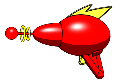
The more realistic render from the same side (sans slight cheated angle):

Retro

Retro game:

68 notes
·
View notes
Text

144 notes
·
View notes
Text
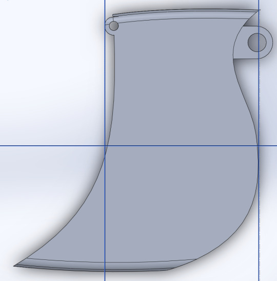
So, in one of my classes, the final was a project where we had creative freedom to design anything we could think of. The only caveat for the project was that we had to design something capable of being tested in an engineering capacity.
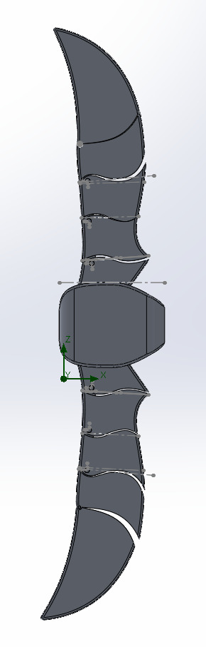
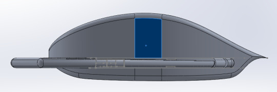
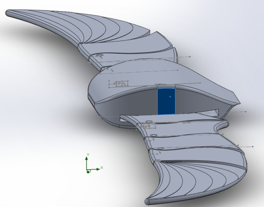
Due to my recent hyperfixation with Marvel and the MCU in general, I decided to try and model a version of Falcon's wingsuit for the project, and now that it's been graded, I wanted to post the results here!
The design took around 15 hours total in the SOLIDWORKS 3D modeling and simulating software for Engineering purposes from initial concept to the final product
Each of the individual wing sections can rotate individually (I'll try and find a way to screen record messing with the assembly to show it sometime)
It was modeled to fit my own proportions (for the purpose of the project, and easier to find reference)
It was actually deemed successful in one of the tests I tried on it!
Please let me know what you think! (only if you want to!)


#sam wilson#the falcon#the falcon and the winter soldier#captain america#fanart#3d model#marvel#marvel cinematic universe#mcu#marvel mcu#my design#mcu fandom#solidworks#design#falcon
35 notes
·
View notes
Text

fml why did i decide to do this
im already three hours in so no turning back i guess
#glados#portal#glados portal#3d printing#3d model#solidworks#god this is gonna take years off my life i think. the features tab is already so unbelievably fucked up
10 notes
·
View notes
Text
Solidworks & AutoCAD 2D 3D Drawing CAD Exercises for Mechanical engineering.
7 notes
·
View notes
Text
CAD Professor: "I will demonstrate you later."
#i dont remember the context#but it sounds threatening#college#university#student#student life#quote blog#dialogue#quotes#college quotes#university quotes#school#mechanical engineering#solidworks
6 notes
·
View notes
Text

─── ・ 。゚☆: *.☽ .* :☆゚. ────── ・ 。゚☆: *.☽ .* :☆゚. ────── ・ 。゚☆:

𝓜𝓪𝓻𝓬𝓱 4𝓽𝓱, 2024
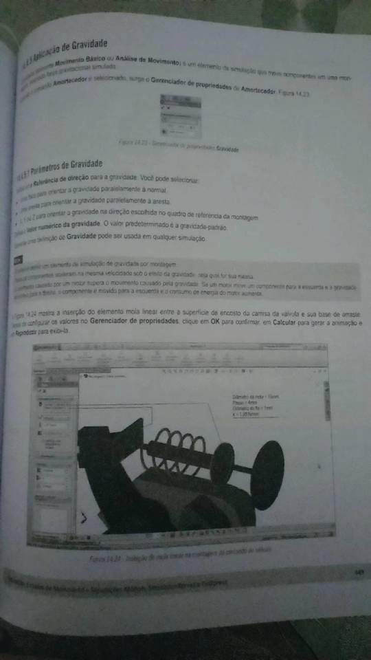
Today I read the chapters about simulation from the Solidwork's book that I got from my father. Since I had physics and calculus classes yesterday, I reviewed some concepts I learned yesterday.
I have another applied physics report to write, this time it's about displacement in fluids and the forces involved, it looks like I'll have activities like this frequently, so this semester will be very busy.
#stem#studyspo#studyblr#studyinspo#stem academia#studying#study motivation#study aesthetic#calculus#engineering#student life#student#stemblr#computer engineering#college#university#solidworks
27 notes
·
View notes
Text


205.637.00.000 Mixture unloading unit. 2019.
7 notes
·
View notes
Text
2D to 3D Drawing Conversion Services: Transforming Designs with Precision

2D to 3D Drawing Conversion Services: Transforming Designs with Precision
Introduction
In the modern design and engineering world, the transition from 2D to 3D drawings has become crucial for enhanced visualization, accuracy, and efficiency. At ADSBIM, we specialize in 2D to 3D drawing conversion, offering precision-driven solutions to transform flat drawings into comprehensive 3D models. Our expertise ensures seamless conversion, catering to industries like architecture, engineering, and manufacturing. We are recognized as the BEST 2D to 3D Drawing Conversion Services provider in Gurgaon, India, UK, Dubai, and USA.
The Process of Converting 2D Designs into 3D Models
The 2D to 3D drawing conversion process involves several meticulous steps to ensure accuracy and fidelity to the original design. Here’s how we do it:
Understanding Requirements: We analyze the 2D drawing, ensuring clarity in dimensions, annotations, and details.
Software Selection: Based on project needs, we choose the appropriate 2D to 3D drawing conversion software such as AutoCAD, SolidWorks, Revit, or CATIA.
Modeling the Geometry: Using advanced tools, we create a 3D representation of the 2D drawing while maintaining proportional accuracy.
Material and Texture Application: If required, materials, textures, and colors are applied to make the model more realistic.
Validation and Quality Check: The final 3D model is compared with the original 2D drawing to ensure precision and adherence to client requirements.
Final Delivery: The completed 2D drawing to 3D model is delivered in the required format, ready for use in design simulations, manufacturing, or visualization.
Challenges in 2D to 3D Drawing Conversion
While converting 2D drawings to 3D models, several challenges can arise:
Loss of Information: Some 2D drawings lack depth-related data, requiring intelligent interpretation.
Complex Geometries: Intricate designs may need additional modifications to ensure a smooth 3D transformation.
Scale and Accuracy: Ensuring precise measurements during conversion is crucial to avoid design flaws.
Software Compatibility: Different clients use varied software, requiring expertise in multiple platforms.
How ADSBIM Provides the Best Solutions
At ADSBIM, we tackle these challenges with expertise and cutting-edge technology:
Experienced Team: Our skilled professionals have extensive experience in 2D to 3D drawing conversion across multiple industries.
Advanced Software Tools: We use industry-leading 2D to 3D drawing conversion software, including:
AutoCAD
SolidWorks
Revit
CATIA
SketchUp
Custom Solutions: We tailor our approach to match specific project needs, ensuring maximum accuracy.
Quality Assurance: Rigorous quality checks ensure error-free 2D drawing to 3D model conversion.
Fast Turnaround: Our efficient process ensures timely delivery without compromising quality.
Why Choose ADSBIM for 2D to 3D Drawing Conversion?
BEST 2D to 3D Drawing Conversion Services COMPANY IN GURGAON and globally recognized in India, UK, Dubai, and USA.
Precision and Accuracy: Our models maintain the highest standards of accuracy.
Affordable Solutions: We provide competitive pricing while maintaining high quality.
Comprehensive Support: From consultation to post-conversion support, we ensure seamless collaboration.
Multi-Industry Expertise: We cater to architecture, engineering, manufacturing, and more.
FAQs for 2D to 3D Drawing Conversion Services
What is the benefit of converting 2D drawings to 3D models?Converting 2D to 3D drawing enhances visualization, accuracy, and efficiency, making designs easier to understand and modify.
Which industries require 2D to 3D drawing conversion services?Industries like architecture, engineering, manufacturing, automotive, and product design benefit from BEST 2D to 3D Drawing Conversion Services.
Which software is used for 2D to 3D drawing conversion?We use AutoCAD, SolidWorks, Revit, CATIA, and SketchUp for 2D to 3D drawing conversion software solutions.
How much time does it take to transform a 2D drawing into a 3D model?The time required depends on the complexity of the drawing and project specifications, but we ensure fast turnaround times.
Do you provide 2D to 3D drawing conversion services globally?Yes, ADSBIM offers BEST 2D to 3D Drawing Conversion Services in India, UK, Dubai, USA, and beyond.
Conclusion
The transition from 2D drawing to 3D is essential for better visualization, accuracy, and manufacturing efficiency. With ADSBIM’s 2D to 3D drawing conversion services, businesses can seamlessly transform their designs into high-quality 3D models. Whether for prototyping, construction, or product development, we provide precise, reliable, and cost-effective solutions tailored to your needs.
Looking for expert 2D to 3D drawing conversion services? Contact ADSBIM today and let us bring your designs to life!
#adsbim#2Dto3DConversion#2Dto3DServices#DrawingConversion#CADConversion#3DModeling#AutoCAD#SolidWorks#Revit#CATIA#SketchUp#ArchitectureDesign#EngineeringDesign#ManufacturingDesign#ProductDesign#2Dto3DModeling#DesignVisualization#ADSBIM#Gurgaon#India#UK#Dubai#USA#CADExperts#TechnicalDesign#3DRendering#EngineeringSolutions
3 notes
·
View notes
Text


youtube
Amaze your friends and family with the MÖBIUS FLIP, a physics toy inspired by the mathematics surface known as the Möbius strip, a surface that has only one side and one edge. On the Flip, the coaster cars traverse a different “side” of the tracks on each revolution—though it's really the same side… and a single rail! Ponder the wonders of topology every time you fidget. Available now on MAKER WORLD.
#toy#80s aesthetic#retro aesthetic#industrial design#3d printing#3d#blender#solidworks#mobius strip#product imagery#Youtube
3 notes
·
View notes
Text
Need to create accurate NPT thread in Solidworks '23? I've created some handy library features to help do that!
These are not models themselves, but a resource for creating tapered pipe thread in solidworks models. These tools have been developed by me and tested while making prototypes of fluid control products out there today. But I no longer work at that place, so I'm sharing!
You can get them free on Thingiverse.
13 notes
·
View notes
Text

Industrial Gear system Assembly in Solidworks
5 notes
·
View notes
Text
when all else fails, close the program and re-fucking-start
#this is about solidworks#solidworks#damn i cant believe theres a tag for that#i have a love-hate relationship with this software#right now im experiencing hate#engineering#mechanical engineering#college#cad software
4 notes
·
View notes
Text
I decided to model my wedding band in solidworks for fun and then decided to print it, also for fun. The real one is silver in color and the print was in black and looked really cool so I decided to print in all the colors I have access to.
Now I have a bunch of copies of my ring in colorful plastic and I'm not really sure what to do with it, but I'm starting to get Sauron's whole thing
3 notes
·
View notes
Text

Podcast.
3d model by Andrew Whitham.
3 notes
·
View notes
Text
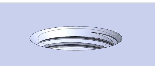
November 15th, 2023
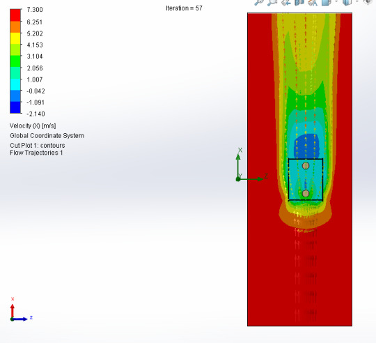
These photos are from the air flow simulation I did yesterday, to find out what impact the wind would have on the structure of the identification buoy. I recorded the animations to make it easier to analyze.
It was fun to do this, I discovered that I can make several different types of fluids, which could be useful in future projects. The article is almost ready, along with the boat and buoy codes.
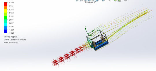
Here are the charts with results generated from Solidworks:

Generally I don't do this, but I'll put the translation of the analysis I put in the article here, maybe it can help someone.
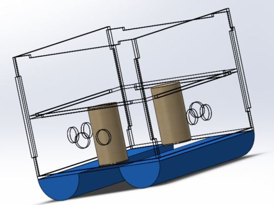
Although it is not common to carry out engineering tests in this specific context, we chose to conduct an analysis dedicated to aerodynamic conditions, aiming to understand the effect of wind on the structural integrity of the buoy. To carry out this study, we used Solidworks, making use of the fluid simulation system incorporated into the program.
Initially, we modeled the buoy structure, assigning specific materials to each component. Subsequently, we establish the necessary boundary conditions to faithfully simulate the behavior of the structure in real conditions. In the next step, we created surfaces that represent the wind pressure in the region where it impacts the buoy, and defined the area in which the wind pressure would be applied. The application of wind loads and adjustment of analysis settings were carried out using the “Flow Simulation” tool.
This process allowed an accurate representation of the aerodynamic conditions on the buoy structure. Additionally, we adjust relevant parameters for the analysis, ensuring a comprehensive approach.
The simulation execution culminated in the generation of a comprehensive report, documenting the results obtained. The interpretation of these results provided valuable insights into the structure's performance under simulated aerodynamic conditions. This engineering test highlighted the importance of considering aerodynamic conditions when assessing structural integrity.
It is possible to highlight some fundamental reasons for the importance of this analysis, such as the assessment of structural integrity, assessment of operational safety, design optimization, which can result in savings in materials and manufacturing costs.
The Montagem_boia.SLDSAM model was configured with standard parameters, carrying out 57 iterations to achieve convergent results. The mesh was defined with basic dimensions (Nx = 40, Ny = 9, Nz = 17), and boundary conditions were established to represent the fluid environment of interest.
The physical time interval considered was 0 seconds, and the CPU time required for the simulation was also recorded. The simulation results revealed an interesting distribution of fluid properties and flow characteristics. The total number of cells in the mesh was 7626, all occupied by the fluid. Among these, 1106 cells were in direct contact with solids.
The mesh dimensions (X,Y,Z) indicated a significant extension of the model, with minimum and maximum variations in each direction. Analysis of the velocity field revealed a range of [0 m/s; 7,510 m/s], indicating different flow regimes within the simulation domain. The pressure varied between [101294.37 Pa; 101430.23 Pa], with a reference pressure of 101325.00 Pa. The temperature remained relatively constant, with values varying from [293.20 K; 293.21 K]. The fluid density showed a minimum variation, within the range of [1.20 kg/m^3; 1.21 kg/m^3].
There was no consideration of factors such as heat in solids, radiation, porous media and gravity to simplify the model to meet the specific objectives of this simulation. Based on the analysis of the images obtained, the reduction in wind speed becomes visible when facing the structure of the identifying buoy.
Notably, the average wind speed in São Paulo, situated at 25km/h, is insufficient to cause damage to the aforementioned structure or to displace it from its original position. It is also worth noting that, when encountering the obstacle represented by the buoy, the wind flow tends to bypass the structure mostly from above, to the detriment of the sides.
This observation suggests an effective resistance of the buoy to direct wind impact, contributing to its stability and structural robustness. The results clearly indicate that the structure's resistance to wind action is remarkable, since the force exerted by the wind did not reach levels that would compromise the integrity or stability of the configuration.
The solidity of the structure in the face of these conditions suggests that the design presents a robust and adequate response to the expected wind loads.
Sorry for any grammatical errors ~
#stem#studyblr#stem academia#studyspo#study motivation#studyinspo#study aesthetic#engineering#studying#solidworks#3d model#computer engineering#mathematics#flow simulation#cad
17 notes
·
View notes