
huimultd-solid-state-relays
HUIMU Industrial-Solid State Relay (SSR) manufacturer & Supplier
176 posts
HUIMU Industrial (HUIMULTD) is an industrial control products manufacturer and automation parts supplier. We provide industrial products and services to global companies. Our team prides itself on providing market-leading products and providing customers with the service and support they deserve.
Don't wanna be here? Send us removal request.
Statistics
We looked inside some of the posts by huimultd-solid-state-relays and here's what we found interesting.
Average Info
Notes Per Post
0
Likes Per Post
0
Reblog Per Post
0
Reply Per Post
0
Time Between Posts
23 hours
Number of Posts By Type
Text
17
Last Seen Tumblr Blogs


Fun Fact
12.7% of mobile users access Tumblr.
Text
Accessories-Related parts of timer switch and timer module
The following on this page provides the basic information of the accessories. If you are interested in one of these products, you can click the "Product Number" or " More" to get more information.
Time Control Switch Chip Module

JFT-16-0.1(Black frame)

JFYB-10-7A(White frame)

JFYB-10-7A(Black frame)

JFYB-66-10.2(White frame)

JFYB-66-10.2(Black frame)

TP8A16-A16
ircuit Board and Probe

Rain & Optical control circuit board

Rain & Optical control probe

Light control probe

Liquid level probe
0 notes
Text
DF Series Intelligent Liquid Level Controller
DF SeriesIntelligent Liquid Level Controller
Introduction
DF series intelligent high and low liquid level controllers with built-in integrated circuits are specially designed for the water pool management of family and factories. DF series smart water level controllers are widely used in various industrial fields, such as printing, dyeing, chemical, food, feed, wine, and sugar. With high-precision water level probes, DF series intelligent water level controller can realize automatic water replenishment and drainage of the water pool, as well as combined control of upper and lower pools. DF series water level controller also has functions such as water shortage protection, which can prevent the water pool from overflowing due to high water level and damage to the pump due to idling. DF series water level controllers are suitable for "Water tower-Well" water supply systems in cities, towns, rural areas, schools, factories, and mines, as well as the water level elevation of urban high-rise buildings. According to the installation method, DF series water level controllers can be divided into wall-mounted type (DF-96A, DF-96B, DF-96C) and DIN rail mounted type (DF-96D).
Parameters

DF-96A/96B/96C (Wall Mount)
Operation Voltage: DF-96A/96B/96C: AC220V; DF-96C: AC380V;50/60Hz (or other customized voltage) Switching Capacity: 16A (DF-96A),20A (DF-96B/C); COS=0.9 Weight: 350g Dimensions: 126×88×51mm Mounting: Wall Signal distance: ≤30m(the cable length can be customized according to specific requirement)

DF-96D (DIN Rail Mount)
Operation Voltage: AC200V±10%,50/60Hz Switching Capacity: 5A; COS=0.9 Weight: 165g Dimensions: 100×50×74mm Mounting: Rail Signal distance: ≤150m (the cable length can be customized according to specific requirement)
Note: The switching capacity in the above basic parameters is based on resistive load. If the load is an inductive load or a capacitive load, the corresponding switching capacity is 30-40% of the resistive load.
Dimensions & Wiring Diagram
DF-96A/96B/96C (Wall Mount)
1 Single Phase Power Supply 1.1 Direct control method (as shown in Figure 1) Applicable object: single-phase AC water pump, and the power consumption of the controlled water pump does not exceed the rated switching capacity of the water level controller. 1.2 Single-phase expansion method (as shown in Figure 2) Applicable object: single-phase AC water pump, and the power consumption of the controlled water pump exceeds the rated switching capacity of the water level controller. If this wiring method is adopted, the output terminal of the water level controller needs to be connected to a single phase AC contactor whose switching capacity should larger than the power consumption of the load to expanse the switching capacity of the water level controller. For DF-96A and DF-96B, you should choose an AC contactor whose coil voltage is 220VAC; for DF-96C, you should choose an AC contactor whose coil voltage is 380VAC. 2 Three Phase Power Supply Applicable object: Three-phase AC water pump. If this wiring method is adopted, the output terminal of the water level controller should be connected to a three-phase AC contactor. 2.1 If the coil voltage of the AC contactor is 220VAC/50Hz, please wire the DF-96A or DF-96B as Figure 3.1 shows. 2.2 If the coil voltage of the AC contactor is 380VAC/50Hz, please wire the DF-96A or DF-96B as Figure 3.2 shows. 2.1 If the coil voltage of the AC contactor is 380VAC/50Hz, please wire the DF-96C as Figure 3.3 shows.

DF-96A/96B/96C wiring diagram 1

DF-96A/96B/96C wiring diagram 2
DF-96D (DIN Rail Mount)
As shown in Figure 4, the output contacts of DF-96D are a normally open contact (PORT4) and a normally closed contact (PORT5). According to actual needs, you can choose different wiring method (Normally Open, Normally Close, Single Pole Double Throw). 1 Single Phase Power Supply 1.1 Direct control method (as shown in Figure 5) Applicable object: single-phase AC water pump, and the power consumption of the controlled water pump does not exceed the rated switching capacity of the water level controller. 1.2 Single-phase expansion method (as shown in Figure 6) Applicable object: single-phase AC water pump, and the power consumption of the controlled water pump exceeds the rated switching capacity of the water level controller (resistive load 10A, inductive load 5A). If this wiring method is adopted, the output terminal of the water level controller needs to be connected to a single phase AC contactor whose switching capacity should larger than the power consumption of the load to expanse the switching capacity of the water level controller. 2 Three Phase Power Supply Applicable object: Three-phase AC water pump. If this wiring method is adopted, the output terminal of the water level controller should be connected to a three-phase AC contactor whose coil voltage is 220VAC/50Hz (as shown in Figure 7).

DF-96D wiring diagram
Instructions For Use (How to set)
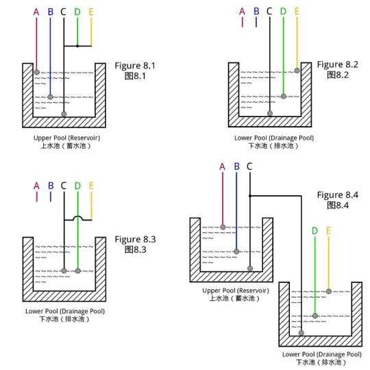
1 What is the function of each probe (water level control wire)
A (Red Wire): It is the upper limit water level control point of the upper pool (reservoir). When the water level rises to A point, the water surface contacts the probe A, and the water level controller automatically turns off the water pump and stops water injection. B (Blue Wire): It is the lower limit water level control point of the upper pool (reservoir). When the water level drops below B point, the water surface is out of contact with the probe B, and the water level controller automatically turns on the water pump to start water injection. C (Black Wire): It is the ground wire of the pool (reservoir). It needs to be placed at the lowest point of the pool in contact with the bottom of the pool. D (Green Wire): It is the lower limit water level control point of the lower pool (drainage pool). The water level drops below D point, the water surface is out of contact with the probe D, and the water level controller automatically shuts off the water pump and stops draining. E (Yellow Wire): It is the upper limit water level control point of the lower pool (drainage pool). The water level rises to E point, and the water surface touches the probe E, and the water level controller automatically starts the water pump and starts draining.
2 How to wire the probe
2.1 If you control the water level of the upper pool separately, you can connect as shown in Figure 8.1, that is, A is connected to the upper limit of the water level, B is connected to the lower limit of the water level, C is connected to the bottom of the pool, and D and E are connected to C. 2.2 If you control the water level of the lower pool separately, you can connect as shown in Figure 8.2, that is, A and B are not connected, C is connected to the bottom of the pool, D is connected to the lower limit of the water level, and E is connected to the upper limit of the water level. 2.3 If you control the water level of the lower pool separately and also need the water shortage protection function, it can be connected as shown in Figure 8.3, that is, A and B are not connected, C and D are connected to the lower limit of the water level, and E is connected to C. 2.4 If you need to control the upper and lower pools together, you can connect as shown in Figure 8.4, that is, A is connected to the upper limit of the water level of the upper pool, B is connected to the lower limit of the water level of the upper pool, C is connected to the bottom of the upper and lower pools, and D is connected to the lower limit of the water level of the lower pool, and E is connected to the upper limit of the water level of the lower pool (if the lower pool does not need to be drained, it is no need to connect E).
DF series probe installation
When you think there is a fault (FAQs)
1. If it doesn't work after power on 1.1 Check if the red power indicator light is on. If it does not light up, please check whether the wiring of the input and output terminals are in good contact. 1.2 Check whether the "manual/auto" switch on the right side of the product is in the "off" position. If so, please adjust it back to the "auto" position, and the water level controller will automatically enter the working state. 2. If the water level line exceeds or falls below the water level control point, the water pump does not automatically close or open, please turn on/off the water pump manually through the "manual/auto" switch and check 2.1 Whether the position of the probe is deviated, if the installation position is too high (too low), the water surface cannot touch (detach) the probe normally. 2.2 Whether the cable of the probe is correctly connected to the corresponding terminal of the water level controller, and whether there is poor contact or short circuit. 2.3 Whether the probe is corroded or falling off. 2.4 Whether the probe C (ground) has been placed in the lowest position of the pool.
Attentions
1 In order to ensure the normal operation of the water level controller, after installing the water level controller, please check the wiring of the input end and the output end, and whether the connecting wire of the probe is in reliable contact. The actual working environment can be simulated by moving the probe up and down (to contact or leave the water surface) to detect whether the water level controller is installed correctly and functions normally. 2 It is recommended to fix each probe on the inner wall of the pool to prevent the water level controller from malfunctioning due to the shifting of the probe position. If the material of the inner wall of the pool is metal, all probes except probe C (ground) should not be connected to the inner wall to avoid short circuit and cause the water level controller to not work normally. 3 After connecting the cable according to the operating instructions, please check whether the water pump can be turned on or off manually through the "manual/auto" switch on the right side of the controller (DF-96D does not have this switch). After checking, please adjust it back to the "auto" position, and the water level controller will enter the automatic working mode. 4 If you need to turn on/off the water pump temporarily, please control it through the "manual/auto" switch on the right side of the water level controller (DF-96D does not have this switch). 5 In order to avoid malfunction, please do not install the water level controller in humid, corrosive and high metal content gas environment. 6 It is recommended to use the probe produced by our company.
0 notes
Text
JFUK Series Intelligent Liquid Level Controller (Float Control Switch)
JFUK SeriesIntelligent Liquid Level Controller (Float Control Switch)
Introduction
JFUK series liquid level controller (also known as float control switch, cable float switch, or float water level controller) is a switch that can adjust the liquid level in the liquid containers (such as pools, barrels, tanks, tanks, reservoir, water tower etc.). JFUK series float controller is composed of the controller body and control signal cables. JFUK series has the advantages of easy installation, easy operation, automatic adjustment, safety and reliability, maintenance-free, non-toxic and environmental protection, and can resist the erosion of sewage. JFUK series is widely used in households, factories, mines, etc. According to the shell material of the controller body, JFUK series can be divided into plastic type float controller (JF-UK221) and 304 stainless steel type float controllers (JF-UK304). JF-UK221 can be used in oil, weak acid and weak base environments, but not in high temperature environments. JF-UK304 can be used in high temperature, strong acid, strong alkali environment.
Parameters

JF-UK221 (Plastic)
Operation Voltage: 220VAC, 380VAC/50HZ Rated Current: 8A(220VAC); 4A(380VAC);COS=0.9 Operation Temperature: 0℃~80℃ Mechanical life: ≥5000 times Liquid Level Control Range: ≥0.2 meter Cable Length: 4 meters (the cable length can be customized according to specific requirement)

JF-UK304 (Stainless Steel)
Operation Voltage: 220VAC, 380VAC/50HZ Rated Current: 8A(220VAC); 4A(380VAC); COS=0.9 Operation Temperature: 0℃~120℃ Mechanical life: ≥5000 times Liquid Level Control Range: ≥0.2 meter Cable Length: 4 meters (the cable length can be customized according to specific requirement)
Dimensions & Wiring Diagram
JFT02 (DIN Rail Mount)
1. Water supply system If JFUK series controller is used for water supply system, black and blue cables should be used. When the float is at the lower water level, it will be connected. When the float is at the upper water level, it will be disconnected.
2. Drainage system If JFUK series controller is used for drainage system, black and brown cables should be used. When the float is at the lower water level, it will be disconnected. When the float is at the upper water level, it will be connected.
3. Use scenarios Due to the diversity of the actual application, JFUK series controller has many wiring methods, which we cannot list them all here. Therefore, in the following we will show the main three wiring methods through three scenes. Scene 1: In this scene, we use JFUK series controller to control a single-phase water pump for automatic water supply (as shown in Figure 1). If the water source is abnormal, in order to prevent damage to the pump equipment, please refer to the wiring method in Scene 3. Scene 2: In this scene, we use JFUK series controller to control a single-phase water pump for automatic drainage (as shown in Figure 2). Scene 3: In this scene, two sets of JFUK series controllers connected in series are used to control a three-phase water pump (as shown in Figure 3). In this way, it can not only ensure the automatic water supply to the water tower, but also prevent damage to water pump equipment due to insufficient water supply in the well. *Note: The above wiring method is for reference only. The unused cables of JFUK series controller must be absolutely insulated!

JFT02 dimensions and wiring diagram 1

JFT02 dimensions and wiring diagram 2
Instructions For Use (How to set)
1 Pass the cable through the plastic plumb, and remove the plastic fixing ring from the top of the plumb.
2 Place the fixing ring to the needed position on the cable.
3 Push the plumb to the position of the fixed ring, and fix its bottom by the fixing ring.
4 Copper wire or other things can be used to fix the top of the plumb to firmly fix it on the cable or on the inner wall of the container to prevent the sliding of the plumb.
JFUK series instructions for use
0 notes
Text
KG3022D, KG3022T, DSK Series Digital Programable Electric Bell Controller
KG3022D, KG3022T, DSK SeriesDigital Programable Electric Bell Controller
Introduction
The digital programable electric bell controller can directly control the electric bell, which is widely used in factories, schools, etc. The microcomputer bell controller has features such as LCD display, easy installation, low timing error, long bell time, long interval time, and many groups of time settings. The microcomputer bell controller can also achieve more functions through external equipment. For example, a bell controller equipped with a voice device can provide voice prompts for homes and enterprises, and also realize timely warning effects; a bell controller equipped with irrigation devices can provide regular watering function for farmland and greenhouses. According to the maximum times of ringing per day, the ringing controller can be divided into 20 times ringing type (KG3022D, DSK-20) and 80 times ringing type (KG3022T, DSK-80), and the former normally applies to factories, and the later normally applies to schools. Besides, KG3022D is the upper wiring, DSK-20 and DSK-80 is the lower wiring, and KG3022T has an electromagnetic shield.
Parameters

DSK-20 (20 Times, Down Wire)
Timer Range: 1min≤t≤168h (cycle work daily or weekly) Operation Voltage: AC220V/50Hz (or other customized voltage) Ringing Duration: 1~59 seconds Operation Temperature: -20℃~60℃ Switching Capacity: 16A (resistive load) Battery: 5AA battery Consumption Power: ≤3W Number of Settings: 20 groups per day Time Error: ≤2 s/day (25℃) Dimensions: 126×88×51mm Mounting: Wall/Rail

DSK-80 (80 Times, Down Wire)
Timer Range: 1min≤t≤168h (cycle work daily or weekly) Operation Voltage: AC220V/50Hz (or other customized voltage) Ringing Duration: 1~99 seconds Operation Temperature: -20℃~60℃ Switching Capacity: 16A (resistive load) Battery: 5AA battery Consumption Power: ≤3W Number of Settings: 80 groups per day, with anti-mistouch button lock Time Error: ≤2 s/day (25℃) Dimensions: 126×88×51mm Mounting: Wall/Rail

KG3022D (20 Times, Upper Wire)
Timer Range: 1min≤t≤168h (cycle work daily or weekly) Operation Voltage: AC220V/50Hz (or other customized voltage) Ringing Duration: 1~59 seconds Operation Temperature: -20℃~60℃ Switching Capacity: 16A (resistive load) Battery: 5AA battery Consumption Power: ≤3W Number of Settings: 20 groups per day Time Error: ≤2 s/day (25℃) Dimensions: 120×74×58mm Mounting: Wall/Rail

KG3022T (80 Times, Lay Flat)
Timer Range: 1min≤t≤168h (cycle work daily or weekly) Operation Voltage: AC220V/50Hz (or other customized voltage) Ringing Duration: 1~99 seconds Operation Temperature: -20℃~60℃ Switching Capacity: 16A (resistive load) Battery: 5AA battery Consumption Power: ≤3W Number of Settings: 80 groups per day, with anti-mistouch button lock Time Error: ≤2 s/day (25℃) Dimensions: 179×139×66mm Mounting: Lay flat
Dimensions & Wiring Diagram
KG3022D, KG3022T, DSK Series
1 DSK-20, DSK-80 wiring diagram (Figure 1) 2 KG3022D wiring diagram (Figure 2) 3 KG3022T wiring diagram (Figure 3) Note: The bell controller can only be connected to 220VAC power supply, not 380VAC power supply.

KG3022D, KG3022T, DSK series dimensions and wiring diagram
Instructions For Use (How to set)
Please make sure that you have understood the functions of all the buttons on the panel (button area), and perform the actual operation according to the instructions.
1 Description of buttons and indicators
CLOCK (): Press to display your local time (it should be set by yourself: you can press and hold the "CLOCK" key to enter the "Time Adjustment Mode", and adjust the "WEEK", "HOUR", and "MINUTE" key to set the local time). PS: If no operation is performed within 30 seconds, the timer switch will automatically display the local time. TIMER(): Press to enter the "Editing Mode", and then set the time to switch the load by adjusting the "WEEK", "HOUR", and "MINUTE" key. WEEK (D+): Adjust week or day. There are various working modes, such as "Five-day Mode" (Monday to Friday), "Six-day Mode" (Monday to Saturday), "Weekend Mode" (Saturday, Sunday), "Daily Mode" (Monday to Sunday), and "Three-day Mode" (Mon-Wed-Fri; Tue-Thu-Sat; Mon-Tue-Wed; Thu-Fri-Sat). HOUR (H+): Adjust hour. MINUTE (M+): Adjust minute. AUTO/MANU (MANUAL): Switch the three switching mode of "ON", "AUTO" and "OFF". For multiple-output timer switches, the output combination can be configured through the "AUTO/MANU" key when in the "Editing Mode" RESET/RECALL (Cancel/Restore, C/R): Press to cancel or restore the timing setting. PS: For products with button lock function, press the " RESET/RECALL " key four times to lock or unlock all buttons. C: Long press the "C" key to clear all settings of the timer switch. POWER LED: When the Power LED (red) is on, it means that the timer switch has been successfully connected to the power source. WORK LED: When the Power LED (red) and the Work LED (green) are on at the same time, it means that the load is powered on.
2 Operating instructionsStep 1. Timing setting (ring time)
Press the " TIMER " button to enter the "Editing Mode". At this time, the "1ON" symbol will appear at the bottom left of the LCD screen (that is, the first time to turn on the electric bell, as shown in Figure 4), and then press the "WEEK" to select Working Mode, and then press the "HOUR" and "MINUTE" keys to input the required ringing time.
Step 2. Timing setting (number of groups)
After completing the first group of timing setting, press the "TIMER" button again, the LCD display will show the "2ON" symbol, and you can set the second set of time setting. According to actual needs, you can repeat steps 1 to set many time groups (the maximum programmable group number depends on the product's built-in chip). If you want to exit the "Editing Mode", you can press the "CLOCK" key to exit it.

Timing Setting 1
Step 3. Timing setting (ringing duration)
After all the groups are set, continue to press the "TIMER" button, and "H10" will appear on the display (Figure 6). At this time, you can press the "MINUTE" button to adjust the ringing duration (1~99 seconds). If you don't adjust, the default ringing duration is 10 seconds.
Step 4. Timing setting (ringing interval)
After the ringing duration is set, continue to press the "TIMER" button, and "45" will appear on the display (Figure 7). At this time, you can press the "MINUTE" button to adjust the ringing interval (1~99min). If you don't adjust, the default ringing interval is 45min. After setting the ringing interval, the bell will ring twice in a time group, that is, double-ring mode; if not set, the bell will only ring once in a time group, that is, single-ring mode.
Step 5. RESET/RECALL
After setting a group of time, for example, ring the electric bell at 08:30 every day (Figure 5). If you want to cancel this group, you can press the "RESET/RECALL" button to delete this group of time settings. At this time, the group of time will be reset to the initial state, that is, "--: --" (Figure 4). Under certain conditions (without any key operation or switching to other interfaces within 20 seconds after cancel operation), just press the "RESET/RECALL" button again to restore this group of time settings.
Step 6. AUTO/MANU
The bell controller has two switching modes: automatic and manual. In the automatic mode, the bell controller will be set according to the timing of steps 1 to 3, and the electric bell will be automatically turned on or off at the corresponding time without human intervention. In manual mode, the electric bell must be turned on or off by manual adjustment. The specific operations are as follows: 1) If you need to turn on the electric bell manually, you can click the "AUTO/MANU" button to switch the "▼" symbol on the display to the "ON" position (Figure 8). At this time, the electric bell will always be in the on state and cannot be turned off automatically. 2) If you need to turn off the electric bell manually, you can click the "AUTO/MANU" button to switch the "▼" symbol on the display to the "OFF" position (Figure 9). At this time, the electric bell will always be in the off state and cannot be turned on automatically. 3) If you need to switch the electric bell automatically, you can click the "AUTO/MANU" button to switch the "▼" symbol on the display to the "AUTO" position (Figure 10). At this time, the working state of the electric bell will be switching automatically according to the timing setting, without being interfered by humans.

Timing Setting 2
Step 7. Lock and unlock
For the bell controller with button lock (or keyboard lock), you can quick press the "RESET/RECALL" key four times to lock or unlock all the buttons. -How to lock the buttons? In the unlocked state, quick press the "RESET/RECALL" button four times or without any operation within 30 seconds to lock all the buttons (Figure 11). At this time, there will be a "∂" symbol in the bottom left, and you cannot make any settings for the bell controller. -How to unlock buttons? In the locked state, quick press the "RESET/RECALL" button four times to unlock all the buttons (Figure 12), and you can make settings at this time.
When you think there is a fault (FAQs)
Note: When the product fails, please disconnect the power first, and then check the equipment! 1 Check the week If the bell controller does not turn on the electric bell at the set time, it may be that the "WEEK" is not adjusted correctly, please check or reset it according to the method introduced in "Timing Setting". 2 Check the time groups If the first point is confirmed to be correct, but the electric bell still cannot be turned on in the right time, the reason will be that the extra time group has not been cancelled. Please refer to the method introduced in "Timing Setting" to delete it. PS: Only when the display shows "--: --", it means the time group is deleted successful; if it displays "00:00", it means 0 o'clock (24 o'clock), not the deleting success. 3 Check the switching mode If the above two points are confirmed to be correct, but the bell controller still does not work normally, it may be that the bell controller is working in "Manual Mode". You can first adjust the "AUTO/MANU" key to set the bell controller to the right working state of the electric bell (ON or OFF), then switch to the "Automatic Mode". 4 Check the fuse If the above three points are correct and the bell controller still cannot work normally, please open the rear seat insurance cover (terminal cover) and check whether the fuse has been blown. If it is blown, please replace with a new 0.1A~0.3A fuse. 5 Check the power supply If the Work LED (or Output LED) is on when the bell controller is working, but the electric bell cannot be turned on normally, please check whether the voltage of the power supply is too low. If the bell controller is burned out, please check whether the power supply voltage exceeds the rated voltage of the product and whether the power cable is connected incorrectly. 6 Please replace the battery If the LCD screen does not display or the display is not clear, replace the battery with the same specification. (Only for bell controller with replaceable batteries) 7 Please contact us or local distributor If the fault cannot be eliminated by the above methods, please contact us or the distributor (dealer) in your local area.
Attentions
1 In order to prevent the contacts of the bell controller from heating under strong current, be sure to tighten the screws on the terminal when wiring. 2 The electric bell should not be too close to the bell controller. 3 The bell controller can only be connected to 220VAC power supply, not 380VAC power supply. 4 Do not repair, disassemble or modify this bell controller by yourself. If you need to repair and check it, please be sure to entrust a dealership or other authorized unit. 5 Do not touch any terminal on the bell controller after it powered on. 6 This bell controller cannot work in humid, corrosive and high metal content gas environment. And do not let the bell controller come into contact with oil or water.
0 notes
Text
DH48S Series Digital Time Relay
DH48S SeriesDigital Time Relay
Parameters
DH48S series digital time relay acts as a delay element in the control circuit, which can turn on or off the circuit at a predetermined time. DH48S series digital time relay consists of large-scale integrated circuit, has excellent EFT and ESD anti-interference ability, and its delay accuracy can reach 0.01 second. DH48S series digital time relay is a device with time-delay after power-on feature, that is, it starts timing after power-on, and after timing is over, it starts to turn on/off the load. Therefore, the time relay must be set before power-on, and the setting after power-on is invalid.
Parameters

DH48S (1 Set of Passive Output Contact)
Operation Voltage: 220VDC, 380VAC/50Hz Timer Range: (1) 0.01 sec-99.99 sec; (2) 0.01min-99.99min; (3) 0.01hour-99.99hour Number of contacts: 1 set of passive output contact Contact capacity: 5A(250VAC, COSΦ=1); 7A(DC24V) Service Life: Electrical life (>105times); Mechanical life(>106times) Temperature: Working temperature (-5℃~45℃); Storage temperature (-20℃~70℃) Repeat error: ≤1% Installation Method: Rail/Panel/Device/Welding

DH48S-2Z (2 Sets of Passive Output Contact)
Operation Voltage: 220VDC, 380VAC/50Hz Timer Range: (1) 0.01 sec-99.99 sec; (2) 0.01min-99.99min; (3) 0.01hour-99.99hour Number of contacts: 2 sets of passive output contact Contact capacity: 5A(250VAC, COSΦ=1); 7A(DC24V) Service Life: Electrical life (>105times); Mechanical life(>106times) Temperature: Working temperature (-5℃~45℃); Storage temperature (-20℃~70℃) Repeat error: ≤1% Installation Method: Rail/Panel/Device/Welding
Dimensions & Wiring Diagram
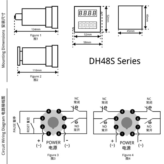
1 Installation method Installation method 1: Wiring by welding (Figure 1) Panel mounting: The hole size is 46mm×46mm. Installation method 2: Wiring by screw crimping. (Figure 2) Panel mounting: The hole size is 46mm×46mm DIN-rail mounting: 35mm rail Device mounting: The hole distance is 33mm, the installation screw is 2-M4×20mm
2 Wiring method DH48S terminal functions: Port 1 and Port 8 are the common terminals; Port 2 is power + or ~, Port 7 is power – or ~; Port 3 is reset terminal; Port 4 is pause terminal; Port 5 is normally close terminal; Port 6 is normally open terminal. DH48S-2Z terminal functions: Port 1 and Port 8 are the common terminals; Port 2 is power + or ~, Port 7 is power – or ~; Port 3 and Port 6 are the normally open terminals; Port 4 and Port 5 are normally closed terminals.
Features: Reset function: As long as the reset terminal is turned on at any time, the time relay will return to the initial state (this function is suitable for DH48S). Pause function: When the pause terminal is turned on during timing, the time relay will stop timing and display the time at the moment; after the pause terminal is turned off, the time relay will continue timing (this function is applicable to DH48S).
DH48S series dimensions and wiring diagram
Instructions For Use (How to set)
Step one. Wiring
Connect the load, switch and power supply to the corresponding terminals of the time relay.
Step two. Time setting
Set the delay time before powering on. (1) 0.01secs~99.99secs (2) 1sec~99mins99secs (3) 1 min~99hours99mins
Step three. Power up
After setting the time relay, turn on the power, then the time relay will display and start timing. Once it reaches the set time, the time delay contact starts to act to realize the delay control of the load. The interval between repeated activations of the time relay should be ≥0.5 seconds. Note: The delay time should be set before power on, any setting after power on is invalid.

DH48S Timing Setting
Attentions
1 When using the time relay, please cover the protective cover at any time to prevent dust from invading and affecting its normal use. 2 When the time relay is used in a strong electric field environment, and its reset and pause wires are long, please use shielded wires. 3 Do not connect the input voltage to the reset and pause terminals of the time relay to avoid damage to the time relay. 4 When the load device current is large, please equip the time relay with a contactor. 5 Please do not repair, disassemble or modify this time relay by yourself. If you need repair and inspection, please entrust a dealership or other authorized unit. 6 Please do not touch any terminal on the time relay after power on. 7 The time relay cannot work in humid, corrosive and high metal content gas environment. Do not contaminate the time relay with oil or water.
0 notes
Text
CN Series Digital Programmable Time Switch (Panel Mount)
CN SeriesDigital Programmable Time Switch (Panel Mount)
Introduction
CN series digital programmable time-controlled switches are specially designed for panel-mounting installation. CN series microcomputer time-controlled switches are composed of LCD digital display, programmable IC chips, buttons, switch components, etc., and are widely used in street lights, neon lights, advertising signs, production equipment, assembly lines, broadcast equipment and other equipment. The CN series digital time control switch adopts a brand-new patch technology, which has the characteristics of stable performance, low power consumption and light weight. The CN series has a built-in rechargeable battery, which can save the data for more than 30 days without power supply. The CN series timer switch are divided into CN101A (JFT18) series and CN304 (JFT19) series.
Parameters

CN101A (Panel Mount)
Timer Range: 1min≤t≤168h (cycle work daily or weekly) Operation Voltage: 220VAC /50Hz (or other customized voltage) Operation Temperature: -10℃-60℃ Switching Capacity: 16A (resistive load) Number of Settings: 16 groups per day, with anti-mistouch button lock Battery: Built-in rechargeable Ni-MH battery Consumption Power: ≤3W Weight: 100g Dimensions: 60×60×30mm Mounting: Panel/Wall

CN101A (Panel Mount)
Timer Range: 1min≤t≤168h (cycle work daily or weekly) Operation Voltage: 220VAC /50Hz (or other customized voltage) Operation Temperature: -10℃-60℃ Switching Capacity: 16A (resistive load) Number of Settings: 16 groups per day, with anti-mistouch button lock Battery: Built-in rechargeable Ni-MH battery Consumption Power: ≤3W Weight: 120g Dimensions: 60×60×30mm Mounting: Panel/Wall
Dimensions & Wiring Diagram
CN Series (Panel Mount)
The installation dimensions and wiring diagram of the CN series timer switch are shown in Figure 1.

CN Series (Panel Mount) dimensions and wiring diagram
Instructions For Use (How to set)
Please make sure that you have understood the functions of all the buttons on the panel (button area), and perform the actual operation according to the instructions.
1 Description of buttons and indicators
CLOCK (): Press to display your local time (it should be set by yourself: you can press and hold the "CLOCK" key to enter the "Time Adjustment Mode", and adjust the "WEEK", "HOUR", and "MINUTE" key to set the local time). PS: If no operation is performed within 30 seconds, the timer switch will automatically display the local time. TIMER(): Press to enter the "Editing Mode", and then set the time to switch the load by adjusting the "WEEK", "HOUR", and "MINUTE" key. WEEK (D+): Adjust week or day. There are various working modes, such as "Five-day Mode" (Monday to Friday), "Six-day Mode" (Monday to Saturday), "Weekend Mode" (Saturday, Sunday), "Daily Mode" (Monday to Sunday), and "Three-day Mode" (Mon-Wed-Fri; Tue-Thu-Sat; Mon-Tue-Wed; Thu-Fri-Sat). HOUR (H+): Adjust hour. MINUTE (M+): Adjust minute. AUTO/MANU (MANUAL): Switch the three switching mode of "ON", "AUTO" and "OFF". For multiple-output timer switches, the output combination can be configured through the "AUTO/MANU" key when in the "Editing Mode" RESET/RECALL (Cancel/Restore, C/R): Press to cancel or restore the timing setting. PS: For products with button lock function, press the " RESET/RECALL " key four times to lock or unlock all buttons. C: Long press the "C" key to clear all settings of the timer switch. POWER LED: When the Power LED (red) is on, it means that the timer switch has been successfully connected to the power source. WORK LED: When the Power LED (red) and the Work LED (green) are on at the same time, it means that the load is powered on.
2 Operating instructionsStep 1. Timing setting (on)
Press the " TIMER " button to enter the "Editing Mode". At this time, the "1ON" symbol will appear at the bottom left of the LCD screen (that is, the first time to turn on the load, as shown in Figure 2), and then press the "WEEK" to select Working Mode, and then press the "HOUR" and "MINUTE" keys to input the required switching on time.
Step 2. Timing setting (off)
Press the " TIMER " button again, the "1OFF" symbol will appear at the bottom left of the LCD screen (that is, the first time to turn off the load, as shown in Figure 3), and then press the "WEEK" to select Working Mode, and then press the "HOUR" and "MINUTE" keys to input the required switching off time. At this time, the first group of timing setting has been completed.

Timing Setting 1
Step 3. Timing setting (number of groups)
After completing the first group of timing setting, press the "TIMER" button again, the LCD display will show the "2ON" symbol, and you can set the second set of time setting. According to actual needs, you can repeat steps 1 and 2 to set many groups (the maximum programmable group number depends on the product's built-in chip). If you want to exit the “Editing Mode”, you can press the "CLOCK" key to exit it.
Step 4. RESET/RECALL
After setting a group of time, for example, turn on the load at 18:30 every day (Figure 5), and turn off the load at 23:20 every day (Figure 6). If you want to cancel this group, you can press the "RESET/RECALL" button to delete this group of time settings. At this time, the group of time will be reset to the initial state, that is, "--: --" (Figure 2 and Figure 3). Under certain conditions (without any key operation or switching to other interfaces within 20 seconds after cancel operation), just press the "RESET/RECALL" button again to restore this group of time settings.
Step 5. AUTO/MANU
The timer switch has two switching modes: automatic and manual. In the automatic mode, the timer switch will be set according to the timing of steps 1 to 3, and the load will be automatically turned on or off at the corresponding time without human intervention. In manual mode, the load must be turned on or off by manual adjustment. The specific operations are as follows: 1) If you need to turn on the load manually, you can click the "AUTO/MANU" button to switch the "▼" symbol on the display to the "ON" position (Figure 6). At this time, the load will always be in the on state and cannot be turned off automatically. 2) If you need to turn off the load manually, you can click the "AUTO/MANU" button to switch the "▼" symbol on the display to the "OFF" position (Figure 7). At this time, the load will always be in the off state and cannot be turned on automatically. 3) If you need to switch the load automatically, you can click the "AUTO/MANU" button to switch the "▼" symbol on the display to the "AUTO" position (Figure 8). At this time, the working state of the load will be switching automatically according to the timing setting, without being interfered by humans.

Timing Setting 2
Step 6. Lock and unlock
For the timer switch with button lock (or keyboard lock), you can quick press the "RESET/RECALL" key four times to lock or unlock all the buttons. -How to lock the buttons? In the unlocked state, quick press the "RESET/RECALL" button four times or without any operation within 30 seconds to lock all the buttons (Figure 9). At this time, there will be a "∂" symbol in the bottom left, and you cannot make any settings for the timer switch. -How to unlock buttons? In the locked state, quick press the "RESET/RECALL" button four times to unlock all the buttons (Figure 10), and you can make settings at this time.
When you think there is a fault (FAQs)
Note: When the product fails, please disconnect the power first, and then check the equipment! 1 Check the week If the timer switch does not turn on or turn off the load at the set time, it may be that the "WEEK" is not adjusted correctly, please check or reset it according to the method introduced in "Timing Setting". 2 Check the time groups If the first point is confirmed to be correct, but the load still cannot be switched correctly on time, the reason will be that the extra time group has not been cancelled. Please refer to the method introduced in "Timing Setting" to delete it. PS: Only when the display shows "--: --", it means the time group is deleted successful; if it displays "00:00", it means 0 o'clock (24 o'clock), not the deleting success. 3 Check the switching mode If the above two points are confirmed to be correct, but the timer switch still does not work normally, it may be that the timer switch is working in "Manual Mode". You can first adjust the "AUTO/MANU" key to set the timer switch to the right working state of the load (ON or OFF), then switch to the "Automatic Mode". 4 Check the fuse If the above three points are correct and the timer switch still cannot work normally, please open the rear seat insurance cover (terminal cover) and check whether the fuse has been blown. If it is blown, please replace with a new 0.1A~0.3A fuse. 5 Check the power supply If the Work LED (or Output LED) is on when the timer switch is working, but the load cannot be switched normally, please check whether the voltage of the power supply is too low. If the timer switch is burned out, please check whether the power supply voltage exceeds the rated voltage of the product and whether the power cable is connected incorrectly. 6 Please replace the battery If the LCD screen does not display or the display is not clear, replace the battery with the same specification. (Only for timer switch with replaceable batteries) 7 Please contact us or local distributor If the fault cannot be eliminated by the above methods, please contact us or the distributor (dealer) in your local area.
Attentions
1 For those equipment (such as medical equipment and large equipment, etc.) that may cause life safety accidents or cause major harm to society due to the error of the timer switch, please do not choose this timer switch. 2 For those equipment (large heaters or cold storage, etc.) that may cause major property losses due to the error of the timer switch, ensure that there is sufficient design margin when using this timer switch, and take safeguard measures such as the double protection circuit. 3 Do not repair, disassemble or modify this timer switch by yourself. If you need to repair and check it, please be sure to entrust a dealership or other authorized unit. 4 Do not touch any terminal on the timer switch after it powered on. 5 This timer switch cannot work in humid, corrosive and high metal content gas environment. And do not let the timer switch come into contact with oil or water.
0 notes
Text
KG316 Series Digital Programmable Street Light Controller
KG316 SeriesDigital Programmable Street Light Controller
Introduction
KG316 series digital street light controller is a kind of timer switch, which is widely used to control street lights, neon lights, advertising signs, factory production equipment, etc. The KG316 series timer switch is based on the KG316T series digital time-controlled switch with rain control and optical control (light control) power-off protection functions. Without any probe installed, the function of the KG316 series is exactly the same as the KG316T series timer switch.
Parameters

KG316-3 (Optical Control)
Timer Range: 1min≤t≤168h (cycle work daily or weekly) Operation Voltage: AC220V/50Hz (or other customized voltage) Operation Temperature: -10℃~ 60℃ Operation Humidity: <95% Switching Capacity: 25A (resistive load); 20A (inductive load) Number of Settings: 10 groups per day Control Mode: Manual, Auto Consumption Power: ≤1W Battery: 7AA battery Time Error: ≤1s/day (25℃) Weight: 260g Dimensions: 120×74×58mm Mounting: Wall/Rail

KG316Y-G (Optical Control, Rain Control)
Timer Range: 1min≤t≤168h (cycle work daily or weekly) Operation Voltage: AC220V/50Hz (or other customized voltage) Operation Temperature: -10℃~ 60℃ Operation Humidity: <95% Switching Capacity: 25A (resistive load); 20A (inductive load) Number of Settings: 10 groups per day Control Mode: Manual, Auto Consumption Power: ≤3W Battery: 5AA battery Time Error: ≤1s/day (25℃) Weight: 260g Dimensions: 126×88×51mm Mounting: Wall/Rail
Dimensions & Wiring Diagram
KG316-3 (Optical Control)
1 Single-phase power supply (there are two wiring methods) 1.1 Direct control method (as shown in Figure 1) Applicable objects: Loads with single-phase power supply, and the power consumption does not exceed the rated capacity of the switch. 1.2 Single-phase expansion method (as shown in Figure 2) Applicable objects: load with single-phase power supply, but the power consumption exceeds the rated capacity of the switch. If this wiring method is adopted, the output terminal of the digital timer switch needs to be connected to a single phase AC contactor whose load capacity should larger than the power consumption of the load to expanse the switching capacity of the timer switch. 2 Three-phase power supply (requires an external three-phase AC contactor) Applicable objects: Loads with three-phase power supply. If the coil voltage of the three-phase AC contactor is AC220V/50Hz, the wiring method shown in Figure 3. If the coil voltage of the three-phase AC contactor is AC380V/50Hz, the wiring method shown in Figure 4.

KG316-3 (Optical Control) dimensions and wiring diagram
KG316Y-G (Optical Control, Rain Control)
1 Single-phase power supply (there are two wiring methods) 1.1 Direct control method (as shown in Figure 5) Applicable objects: Loads with single-phase power supply, and the power consumption does not exceed the rated capacity of the switch. 1.2 Single-phase expansion method (as shown in Figure 6) Applicable objects: load with single-phase power supply, but the power consumption exceeds the rated capacity of the switch. If this wiring method is adopted, the output terminal of the digital timer switch needs to be connected to a single phase AC contactor whose load capacity should larger than the power consumption of the load to expanse the switching capacity of the timer switch. 2 Three-phase power supply (requires an external three-phase AC contactor) Applicable objects: Loads with three-phase power supply. If the coil voltage of the three-phase AC contactor is AC220V/50Hz, the wiring method shown in Figure 7. If the coil voltage of the three-phase AC contactor is AC380V/50Hz, the wiring method shown in Figure 8.

KG316Y-G (Optical Control, Rain Control) dimensions and wiring diagram
Instructions For Use (How to set)
Please make sure that you have understood the functions of all the buttons on the panel (button area), and perform the actual operation according to the instructions.
1 Probe installation and use
1.1 When the KG316 series street lamp controller is not equipped with an optical control probe or a rain control probe, its use method is the same as the KG316T series time control switch. 1.2 Installation and use of optical probe: insert the optical control probe into the "Optical Control" jack. If the probe senses light, KG316 will turn off in about one minute; if there is no light, KG316 will return to its original state after about five minutes (continue to perform work according to the timing program). On-off illumination is 25LX±5LX. 1.3 Installation and use of rain probe: insert the rain control probe into the "Rain Control" jack. If the probe senses rain, KG316 will shut down immediately; if there is no rain, KG316 will return to its original state after about five minutes (continue to work according to the timing program). The power-off resistance is 100KQ, and the power-on resistance is 1MQ. 1.4 Installation and use of optical probe and rain probe at the same time: insert the optical probe and rain probe into the corresponding jacks respectively. As long as it senses light or rain (any of them), KG316 will shut down; if there is neither light nor rain, KG316 will return to its original state after about five minutes (continue to perform work according to the timing program). 1.5 The probe can be available only when KG316 is working in "AUTO" or "ON" mode.
2 Description of buttons and indicators
CLOCK (): Press to display your local time (it should be set by yourself: you can press and hold the "CLOCK" key to enter the "Time Adjustment Mode", and adjust the "WEEK", "HOUR", and "MINUTE" key to set the local time). PS: If no operation is performed within 30 seconds, the timer switch will automatically display the local time. TIMER(): Press to enter the "Editing Mode", and then set the time to switch the load by adjusting the "WEEK", "HOUR", and "MINUTE" key. WEEK (D+): Adjust week or day. There are various working modes, such as "Five-day Mode" (Monday to Friday), "Six-day Mode" (Monday to Saturday), "Weekend Mode" (Saturday, Sunday), "Daily Mode" (Monday to Sunday), and "Three-day Mode" (Mon-Wed-Fri; Tue-Thu-Sat; Mon-Tue-Wed; Thu-Fri-Sat). HOUR (H+): Adjust hour. MINUTE (M+): Adjust minute. AUTO/MANU (MANUAL): Switch the three switching mode of "ON", "AUTO" and "OFF". For multiple-output timer switches, the output combination can be configured through the "AUTO/MANU" key when in the "Editing Mode" RESET/RECALL (Cancel/Restore, C/R): Press to cancel or restore the timing setting. PS: For products with button lock function, press the " RESET/RECALL " key four times to lock or unlock all buttons. C: Long press the "C" key to clear all settings of the timer switch. POWER LED: When the Power LED (red) is on, it means that the timer switch has been successfully connected to the power source. WORK LED: When the Power LED (red) and the Work LED (green) are on at the same time, it means that the load is powered on.
3 Operating instructionsStep 1. Timing setting (on)
Press the " TIMER " button to enter the "Editing Mode". At this time, the "1ON" symbol will appear at the bottom left of the LCD screen (that is, the first time to turn on the load, as shown in Figure 9), and then press the "WEEK" to select Working Mode, and then press the "HOUR" and "MINUTE" keys to input the required switching on time.
Step 2. Timing setting (off)
Press the " TIMER " button again, the "1OFF" symbol will appear at the bottom left of the LCD screen (that is, the first time to turn off the load, as shown in Figure 10), and then press the "WEEK" to select Working Mode, and then press the "HOUR" and "MINUTE" keys to input the required switching off time. At this time, the first group of timing setting has been completed.

Timing Setting 1
Step 3. Timing setting (number of groups)
After completing the first group of timing setting, press the "TIMER" button again, the LCD display will show the "2ON" symbol, and you can set the second set of time setting. According to actual needs, you can repeat steps 1 and 2 to set many groups (the maximum programmable group number depends on the product's built-in chip). If you want to exit the "Editing Mode", you can press the "CLOCK" key to exit it.
Step 4. RESET/RECALL
After setting a group of time, for example, turn on the load at 18:30 every day (Figure 11), and turn off the load at 23:20 every day (Figure 12). If you want to cancel this group, you can press the "RESET/RECALL" button to delete this group of time settings. At this time, the group of time will be reset to the initial state, that is, "--: --" (Figure 9 and Figure 10). Under certain conditions (without any key operation or switching to other interfaces within 20 seconds after cancel operation), just press the "RESET/RECALL" button again to restore this group of time settings.
Step 5. AUTO/MANU
The timer switch has two switching modes: automatic and manual. In the automatic mode, the timer switch will be set according to the timing of steps 1 to 3, and the load will be automatically turned on or off at the corresponding time without human intervention. In manual mode, the load must be turned on or off by manual adjustment. The specific operations are as follows: 1) If you need to turn on the load manually, you can click the "AUTO/MANU" button to switch the "▼" symbol on the display to the "ON" position (Figure 13). At this time, the load will always be in the on state and cannot be turned off automatically. 2) If you need to turn off the load manually, you can click the "AUTO/MANU" button to switch the "▼" symbol on the display to the "OFF" position (Figure 14). At this time, the load will always be in the off state and cannot be turned on automatically. 3) If you need to switch the load automatically, you can click the "AUTO/MANU" button to switch the "▼" symbol on the display to the "AUTO" position (Figure 15). At this time, the working state of the load will be switching automatically according to the timing setting, without being interfered by humans.

Timing Setting 2
Step 6. Lock and unlock
For the timer switch with button lock (or keyboard lock), you can quick press the "RESET/RECALL" key four times to lock or unlock all the buttons. -How to lock the buttons? In the unlocked state, quick press the "RESET/RECALL" button four times or without any operation within 30 seconds to lock all the buttons (Figure 16). At this time, there will be a "∂" symbol in the bottom left, and you cannot make any settings for the timer switch. -How to unlock buttons? In the locked state, quick press the "RESET/RECALL" button four times to unlock all the buttons (Figure 17), and you can make settings at this time.
When you think there is a fault (FAQs)
Note: When the product fails, please disconnect the power first, and then check the equipment! 1 Check the week If the timer switch does not turn on or turn off the load at the set time, it may be that the "WEEK" is not adjusted correctly, please check or reset it according to the method introduced in "Timing Setting". 2 Check the time groups If the first point is confirmed to be correct, but the load still cannot be switched correctly on time, the reason will be that the extra time group has not been cancelled. Please refer to the method introduced in "Timing Setting" to delete it. PS: Only when the display shows "--: --", it means the time group is deleted successful; if it displays "00:00", it means 0 o'clock (24 o'clock), not the deleting success. 3 Check the switching mode If the above two points are confirmed to be correct, but the timer switch still does not work normally, it may be that the timer switch is working in "Manual Mode". You can first adjust the "AUTO/MANU" key to set the timer switch to the right working state of the load (ON or OFF), then switch to the "Automatic Mode". 4 Check the fuse If the above three points are correct and the timer switch still cannot work normally, please open the rear seat insurance cover (terminal cover) and check whether the fuse has been blown. If it is blown, please replace with a new 0.1A~0.3A fuse. 5 Check the power supply If the Work LED (or Output LED) is on when the timer switch is working, but the load cannot be switched normally, please check whether the voltage of the power supply is too low. If the timer switch is burned out, please check whether the power supply voltage exceeds the rated voltage of the product and whether the power cable is connected incorrectly. 6 Please replace the battery If the LCD screen does not display or the display is not clear, replace the battery with the same specification. (Only for timer switch with replaceable batteries) 7 Please contact us or local distributor If the fault cannot be eliminated by the above methods, please contact us or the distributor (dealer) in your local area.
Attentions
1 For those equipment (such as medical equipment and large equipment, etc.) that may cause life safety accidents or cause major harm to society due to the error of the timer switch, please do not choose this timer switch. 2 For those equipment (large heaters or cold storage, etc.) that may cause major property losses due to the error of the timer switch, ensure that there is sufficient design margin when using this timer switch, and take safeguard measures such as the double protection circuit. 3 Do not repair, disassemble or modify this timer switch by yourself. If you need to repair and check it, please be sure to entrust a dealership or other authorized unit. 4 Do not touch any terminal on the timer switch after it powered on. 5 This timer switch cannot work in humid, corrosive and high metal content gas environment. And do not let the timer switch come into contact with oil or water.
0 notes
Text
JFT Series Digital Programmable Street Light Controller
JFT SeriesDigital Programmable Street Light Controller
Introduction
JFT series digital street light controller adopts intelligent micro-processing chip, which can calculate the sunrise and sunset time through the latitude and longitude algorithm according to the operation law of the sun and the earth and the relationship between the latitude and longitude of the earth and the sunrise and sunset. It has the advantages of high reliability, small error, strong stability, and strong anti-interference ability, and can adapt to the needs of different geographic environments. JFT smart street light controller also has a built-in high-energy lithium battery (which can maintain the clock running for more than 10 years without changing the battery), which can effectively protect data in the event of a power failure. JFT intelligent street lamp controller has high-power relay output, which can be directly connected to 220VAC contactor or 380VAC contactor. JFT smart street lamp controllers are widely used in streets, railways, stations, waterways, industrial and mining, schools and power supply departments and other places. The JFT series street lamp controller can be divided into JFT-6 series and JFT-9 series. JFT-6 series street light controller is wall-mounted and has two output circuits (channel A and channel B). JFT-6 street light controllers have several working modes: full-night mode, half-night mode, and 2on-2off mode. According to whether it contains light control device, JFT-6 series can be divided into normal type and light-sense type. JFT-9 series street lamp controller is rail-mounted and has two output circuits (one normally open and one normally closed). JFT-9 series street light controllers have two working modes: full-night mode, and half-night mode.
Parameters

JFT-6 (Latitude and Longitude Control)
Operation Voltage: AC220V/50Hz (or other customized voltage) Operation Temperature: -15℃~60℃ Operation Humidity: <90% Switching Capacity: 10A (resistive load) Working Mode: Full-night mode, half-night mode, 2on-2off mode Consumption Power: ≤1W Battery: Built-in high-energy lithium battery Time Error: ≤±0.5s/day (25℃) Dimensions: 150×100×48mm Mounting: Wall

JFT-9 (Latitude and Longitude Control)
Operation Voltage: AC220V/50Hz (or other customized voltage) Operation Temperature: -40℃~70℃ Operation Humidity: <90% Switching Capacity: 10A (resistive load) Working mode: Mode 0 (user setting); Mode 1 (latitude and longitude control) Number of time periods: Mode 0 (once/month); Mode 1 (daily) Control interval: 24 hours (the minimum step length is 1 minute) Consumption Power: ≤1W Time Error: ≤30s/year (25℃) Dimensions: 100×50×74mm Mounting: Rail
Dimensions & Wiring Diagram
JFT-6
1 JFT6 can carry two loads, LOAD1 (Channel A) and LOAD2 (Channel B). (As shown in Figure 1) 2 JFT6 has two wiring methods, as shown in Figure 2 and Figure 3.

JFT-6 dimensions and wiring diagram
JFT-9
1 Terminal introduction: PORT 1 and PORT 2 are power terminals; PORT 3 is a normally open contact; PORT 4 is a common contact; PORT 5 is a normally closed contact. (As shown in Figure 4) 2 Wiring diagrams: 2.1 Single-phase power supply-direct control method If the load is single-phase power supply, and the power consumption does not exceed the rated capacity of the switch. (As shown in Figure 5) 2.2 Three-phase power supply If the load is three-phase power supply, an external three-phase AC contactor (coil voltage is AC220V/50Hz) is required. (As shown in Figure 6)

JFT-9 dimensions and wiring diagram
Instructions For Use (How to set JFT-6)
Please make sure that you have understood the functions of all the buttons on the panel (button area), and perform the actual operation according to the instructions.
Ⅰ Description of buttons and indicators
SET/SHIFT: Used to set parameters; in the "Check Mode", the displayed parameter group can be switched. CHECK/NEXT: Used to check parameters; in the "Setting Mode", it can be used to select the parameters that need to be modified. MONTH/+: Used to increase the value of the parameter. DAY/-: Used to reduce the value of the parameter. MANU/ON: Used to turn on or off the "Manual Mode". OPERATION LED: When JFT-6 is working normally, the operation LED will flash. MANUAL LED: When JFT-6 is working in "Manual Mode", the manual LED will always be on. OUTPUT 1: When the load 1 is connected to the Channel A, the output 1 LED will always be on. OUTPUT 2: When the load 2 is connected to the Channel B, the output 2 LED will always be on.
Ⅱ Description of working modes
1 Automatic Mode Channel A and Channel B can be set to three automatic working modes-full-night light mode, half-night light mode, 2on-2off light mode. Once set to automatic working mode, the load can be automatically switched on and off every day without human intervention. Full-night working mode (turn on the lights in the evening and turn off the lights in the morning): According to the latitude and longitude information, the switching time of the street light is automatically controlled according to the seasonal change, that is, the street light is automatically turned on in the evening and the street light is automatically turned off in the morning. You can fine-tune the automatic switching time within ±120 minutes (negative means advance, positive means delay). Half-night working mode (turn on the lights in the evening and turn off the lights in the middle of the night): According to the latitude and longitude information, the turn-on time of the street light is automatically controlled according to the seasonal change, that is, the street light is automatically turned on in the evening; the turn-off time needs to be set by yourself. You can fine-tune the auto-opening time in the range of ±120 minutes (negative means advance, positive means delay). The midnight light work mode can effectively save power than the all night light work mode. 2on-2off working mode (turn on the light in the evening and turn off the light in the middle of the night, and turn on the light in the early morning and turn off the light in the morning): On the basis of the half-night working mode, it will add a set of time to turn on the street light for a short time (which should be set by yourself) . This mode is often used to provide street lighting for cleaning staff working in the early morning. 2 Manual Mode Long press the "MANU/ON" button for more than 2 seconds, JFT-6 will enter the "Manual Mode"(or "manual emergency light mode"), at this time JFT-6 will immediately turn on the street lights, and the display will show "MANUAL". In this mode, the switch states of A and B will not be controlled by the program. Long press the "MANU/ON" button for more than 2 seconds, JFT-6 will exit the "Manual Mode", at this time A and B will be automatically switched according to the set program, and the display will no longer display "MANUAL". Manual mode is often used for emergency lighting, equipment maintenance, major celebrations, etc. 3 Light Sensing Mode If you need to turn on the street lights in advance in the evening of rainy days, you can choose the light-sense type JFT-6 (up to 30 minutes in advance). Compared with the normal type JFT-6, the light-sense type JFT-6 is equipped with a light sensor controller, which can turn on the lights in advance according to the change of natural light based on the latitude and longitude switching time. The light-sense type JFT-6 uses fuzzy mathematics to deal with changes in natural light, so it will not be affected by light fluctuations, artificial lighting, etc. during operation. Because light-sense type JFT-6 adopts automatic adjustment technology, it can effectively avoid the actual illuminance detection error caused by the different installation conditions of the photosensitive device and the drift of the device during long-term operation.
Ⅲ Operating instructions
In order to save power consumption, during normal operation, the display screen of JFT-6 will not display anything, only the running light flashes, and the load light (Outpu1 and Output2) is displayed normally. When you press any button or just turn on the power, the LED display will show the "Current Time". If there is no operation, the LED display will turn off after 1 minute.
1 Setting Mode (the detailed process is shown in Figure 7)
1.1 Enter/exit "Setting Mode": Long press the "SET/SHIFT" key to enter the "Setting Mode" (buzzer sounds), at this time the LED display will start to flash, and the flashing value is a modifiable value. Exit the "Setting Mode" (buzzer sounds) through long press the "SET/SHIFT" button or without any operation within 3 minutes. At this time, JFT-6 will automatically save the set parameters, and the LED display will no longer flash and show the current time. 1.2 Select parameters: Display the parameters that need to be modified through the SET/SHIFT" key, and select the values that need to be modified through the "CHECK/NEXT" key. 1.3 Modify parameters: Modify the selected value through "Month/+" key and "Day/-" key.
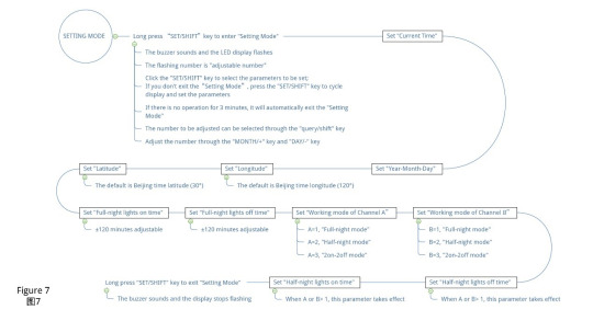
JFT-6 Setting Mode
2 Check Mode (the detailed process is shown in Figure 8)
2.1 Enter/exit "Check Mode": Click the "CHECK/NEXT" button to enter "Check Mode"; without any operation within 15 seconds, it will automatically exit "Check Mode", and the LED display will show the current time. 2.2 Select the parameter group: Click the "SET/SHIFT" button to switch the parameter group to be displayed (GroupⅠand GroupⅡ). 2.3 Check each parameter in the parameter group: Use the "CHECK/NEXT" key to view all the parameter values in the selected parameter group.

JFT-6 Check Mode
Instructions For Use (How to set JFT-9)
Please make sure that you have understood the functions of all the buttons on the panel (button area), and perform the actual operation according to the instructions.
Ⅰ Description of buttons and indicators
"⌒" (function): Used to check and modify parameters; also used to turn on or off the "Test Mode". "∧" (+): Used to increase the value of the parameter; in the "Test Mode", the load can be turned on manually. "∨" (-): Used to reduce the value of the parameter; in the "Test Mode", the load can be turned off manually. OPERATION LED:When JFT-9 is working normally, the running light will flash.
Ⅱ Description of working modes
1 Mode 0 In mode 0, you can set the switch time of street lights in a certain month, and the time range is from 00:00 to 23:59. Once set, the load can be automatically switched on and off every day without human intervention. In mode 0, JFT-9 is not controlled by latitude and longitude during the set month, and its switching load time will not change with the season, so it can be regarded as a digital timer switch. 2 Mode 1 In mode 1, JFT-9 has two working modes: full-night light mode and half-night light mode. Once set, the load will be automatically switched on and off every day without human intervention. Full-night working mode (turn on the lights in the evening and turn off the lights in the morning): According to the latitude and longitude information, the switching time of the street light is automatically controlled according to the seasonal change, that is, the street light is automatically turned on in the evening and the street light is automatically turned off in the morning. You can fine-tune the automatic switching time within ±50 minutes (negative means advance, positive means delay). Half-night working mode (turn on the lights in the evening and turn off the lights in the middle of the night): According to the latitude and longitude information, the turn-on time of the street light is automatically controlled according to the seasonal change, that is, the street light is automatically turned on in the evening; the turn-off time needs to be set by yourself. You can fine-tune the auto-opening time in the range of ±50 minutes (negative means advance, positive means delay). The midnight light work mode can effectively save power than the all night light work mode. 3 Manual Mode In automatic working mode, press the "∧" key or ∨" key to display the light on/off time of the day. At this time, if you press the "⌒" key again, JFT-9 will enter the "Test Mode" and the display screen will show "TEST". In this mode, the switch state of the load will not be controlled by the program, and it cannot be restored to the "automatic mode" by itself. In the "Test Mode", press the "∧" key to manually turn on the light, press "∨" key to manually turn off the lights. Press the "⌒" key again, JFT-9 will exit the "Test Mode" and restore the "automatic mode". The test mode is often used for emergency lighting, equipment maintenance, major celebrations, etc.
Ⅲ Operating instructions
In order to save power consumption, during normal operation, the display screen of JFT-9 will not show anything, and the "Operation" LED will flash. When you press any button or just turn on the power, the LED display will show the "Current Time". If there is no operation, the LED display will turn off after 1 minute.
1 Editing Mode (the detailed process is shown in Figure 9)
1.1 Enter/exit "Editing Mode": Click the "⌒" key to enter "Editing Mode"; if there is no operation within 30 seconds, it will automatically exit the editing mode, and the display will show the current time and return to "Automatic Mode". P.S.: In "Manual Mode", JFT-9 cannot exit the editing mode automatically. 1.2 Modification: Use the "⌒" key to select parameters, and use the "∧" key or ∨" key to modify the parameters.

JFT-9 Editing Mode
2 Test Mode
2.1 Enter/exit "Test Mode": you can enter "Test Mode" from "Editing Mode" or "Manual Mode"; click "⌒" key to exit "Test Mode".
When you think there is a fault (FAQs)
Note: When the product fails, please disconnect the power first, and then check the equipment! 1 Please check whether the settings are correct If the product is not set up correctly, then it cannot work as your needs. 2 Please check the insurance tube Please open the rear seat safety cover (terminal cover) to check whether the fuse has been blown. If it is blown, please replace it with a new 0.1A~0.3A fuse. 3 Please check the power supply Please check whether the power supply voltage is too low and the product wiring is wrong. 4 Please replace the battery If the LCD screen does not display or the display is not clear, replace the battery with the same specification. 5 Please contact us or local distributor If the above methods can not eliminate the fault, please contact our company or local dealer for handling. Do not repair, disassemble or modify this product by yourself. If repairs and inspections are required, please entrust a dealer or other authorized agency.
0 notes
Text
AS, GUK, KGF Series Street Light Controller
Introduction
Street light controller is composed of photoelectric conversion device, relay and etc., which can effectively reduce the consumption of manpower and electricity, so street light is widely used in street lights (factories, schools, streets, airports, farms), and navigation lights on islands. Our street lamp controller has the advantages of strong anti-interference ability, reliable function and high sensitivity, and its work is not affected by the weather and season. Our street light controller is equipped with a delay circuit inside, so it can prevent switching errors action caused by accidental bright lights (such as lightning, flashlights, car lights and other illuminating light sources) and accidental obstructions (such as fallen leaves). AS series street light controller adopts a plastic shell, and it is small in size, good in water resistance, light in weight, but weak in switching capacity. GUK series street light controller adopts a metal shell, and it has strong anti-interference ability and strong switching capacity. KG-F series can be installed on the DIN Rail.
Parameters

AS-10 (Optical Control)
Operation Voltage: AC220V/50Hz (or other customized voltage) Operation Temperature: -10℃~60℃ On-off illumination: 10LX±1LX Switching Capacity: 5A (resistive load) Dimensions: 120×80×80mm

AS-15 (Optical Control)
Operation Voltage: AC220V/50Hz (or other customized voltage) Operation Temperature: -10℃~60℃ On-off illumination: 10LX±1LX Switching Capacity: 15A (resistive load) Dimensions: 120×80×80mm

AS-20 (Optical Control)
Operation Voltage: AC220V/50Hz (or other customized voltage) Operation Temperature: -10℃~60℃ On-off illumination: 10LX±1LX Switching Capacity: 7A (resistive load) Dimensions: 65×65×70mm

ASO (Optical Control)
Operation Voltage: AC220V/50Hz (or other customized voltage) Operation Temperature: -10℃~60℃ On-off illumination: 10LX±1LX Switching Capacity: 10A (resistive load) Dimensions: 50x50×70mm

GUK-81 (Optical Control)
On-off delay: 10s-60s On-off illumination: 10LX (adjustable) Operation Voltage: AC220V/50Hz (or other customized voltage) Rated Current: 10A Operation Temperature: -10℃~60℃ Weight: 1.1kg Working Mode: Automatic Dimensions: 96×104×246mm Mounting: Wall

GUK-82 (Optical Control)
On-off delay: 10s-60s On-off illumination: 10LX (adjustable) Operation Voltage: AC220V/50Hz (or other customized voltage) Rated Current: 40A Operation Temperature: -10℃~60℃ Weight: 1.5kg Working Mode: Automatic Dimensions: 90×104×246mm Mounting: Wall
GUK-83/84 (Optical Control)

On-off delay: 10s-60s On-off illumination: 10LX (adjustable) Operation Voltage: AC220V/50Hz (or other customized voltage) Rated Current: 60A/80A Operation Temperature: -10℃~60℃ Weight: 2.1kg Working Mode: Automatic Dimensions: 83: 113×112×275mm; 84: 335×135×155mm Mounting: Wall

KG-F (Optical Control)
On-off delay: 10s-60s On-off illumination: 10LXL (adjustable) Operation Voltage: AC220V/50Hz (or other customized voltage) Operation Temperature: -10℃~60℃ Switching Capacity: 20A (resistive load) Dimensions: 120×74×51mm Mounting: Wall
Dimensions & Wiring Diagram
AS Series
1 Installation method The correct installation method is shown in Figure 1; the wrong installation method is shown in Figure 2. 2 Wiring method PORT 1 (White) and PORT 2 (Black) are connected to the power supply; PORT 1 (White) and PORT 3 (Red) are connected to the load. For inductive loads (such as fluorescent lamps, high pressure sodium lamps, mercury lamps, metal halide lamps), a current stabilizer should be connected in parallel at the output (Figure 3). For resistive loads (such as incandescent lamps, iodine tungsten lamps, etc.), there is no need to add a current stabilizer (Figure 4).

Mounting and wiring diagram 1
GUK Series
1 Installation method Install the GUK series street lamp controller on a street lamp post or a place with natural light. The sensitivity knob is used to adjust the sensitivity of the photosensitive circuit (Figure 5). 2 Wiring method PORT 1 and PORT 3 are connected to the power supply; PORT 2 and PORT 3 are connected to the load (Figure 6). If the load is an inductive load, a current stabilizer must be connected in parallel at the output terminal.
KG-F Series
1 Installation method Install the KG-F series street light controller on an indoor wall or DIN Rail, and then place its light control probe outdoors to sense changes of the natural light. 2 Wiring diagram Direct control wiring method (Figure 7); expansion wiring method (Figure 8).

Mounting and wiring diagram 2
Attentions
1 Please clean the dust on the light control probe in time or regularly to avoid affecting the photoelectric conversion effect. 2 Please do not repair, disassemble or modify this product by yourself. If you need repair and inspection, please entrust a dealership or other authorized unit. 3 Do not touch any terminals after turning on the power.
0 notes
Text
JFT-16, JFT-17 Series Digital Programmable Time Switch
Introduction
JFT series timer switch can automatically turn on or off the power of various electrical equipment according to the time set by the user. JFT series digital time-controlled switch is consisted of digital LCD display, programmable IC chip, buttons, switching components and etc. JFT series microcomputer timer switch is widely used in street lights, neon lights, advertising signs, production equipment, assembly lines, and broadcast equipment. The new version JFT series digital smart timer switch adopts a brand-new chip technology, which can effectively avoid the false welding and missing welding. Besides, the all-new designed JFT series timer switch has the characteristics of stable performance, low power consumption, light weight, and replaceable power supply battery. JFT-16 is the normal type, and JFT-17 is the economic type. JFT-16 adopts the integrated process of immersion gold craft, and a highly textured shell, and is also equipped with a panel dust cover, but its battery is not removable. JFT-17 has the same performance as KG316T, has a keyboard lock, and its battery can be removed.
Parameters

JFT16
Timer Range: 1min≤t≤168h (cycle work daily or weekly) Operation Voltage: AC220V/50Hz (or other customized voltage) Operation Temperature: -20℃~60℃ Operation Humidity: <95% Switching Capacity: 25A (resistive load) Number of Settings: 8 groups per day Consumption Power: ≤2W Battery: 5AA battery Time Error: ≤2s/day (25℃) Weight: 216g Dimensions: 123×71×58mm Mounting: Wall/Rail

JFT17
Timer Range: 1min≤t≤168h (cycle work daily or weekly) Operation Voltage: AC220V/50Hz (or other customized voltage) Operation Temperature: -10℃~50℃ Operation Humidity: <95% Switching Capacity: 25A (resistive load) Number of Settings: 16 groups per day, with anti-mistouch button lock Consumption Power: ≤2W Battery: 5AA battery Time Error: ≤2s/day (25℃) Weight: 222g Dimensions: 113×64×42mm Mounting: Wall/Rail
Dimensions & Wiring Diagram
JFT-16, JFT-17
1 Single-phase power supply (there are two wiring methods) 1.1 Direct control method (as shown in Figure 1) Applicable objects: Loads with single-phase power supply, and the power consumption does not exceed the rated capacity of the switch. 1.2 Single-phase expansion method (as shown in Figure 2) Applicable objects: load with single-phase power supply, but the power consumption exceeds the rated capacity of the switch. If this wiring method is adopted, the output terminal of the digital timer switch needs to be connected to a single phase AC contactor whose load capacity should larger than the power consumption of the load to expanse the switching capacity of the timer switch. 2 Three-phase power supply (requires an external three-phase AC contactor) Applicable objects: Loads with three-phase power supply. If the coil voltage of the three-phase AC contactor is AC220V/50Hz, the wiring method shown in Figure 3. If the coil voltage of the three-phase AC contactor is AC380V/50Hz, the wiring method shown in Figure 4.

JFT-16, JFT-17 dimensions and wiring diagram
Instructions For Use (How to set)
Please make sure that you have understood the functions of all the buttons on the panel (button area), and perform the actual operation according to the instructions.
1 Description of buttons and indicators
CLOCK (): Press to display your local time (it should be set by yourself: you can press and hold the "CLOCK" key to enter the "Time Adjustment Mode", and adjust the "WEEK", "HOUR", and "MINUTE" key to set the local time). PS: If no operation is performed within 30 seconds, the timer switch will automatically display the local time. TIMER(): Press to enter the "Editing Mode", and then set the time to switch the load by adjusting the "WEEK", "HOUR", and "MINUTE" key. WEEK (D+): Adjust week or day. There are various working modes, such as "Five-day Mode" (Monday to Friday), "Six-day Mode" (Monday to Saturday), "Weekend Mode" (Saturday, Sunday), "Daily Mode" (Monday to Sunday), and "Three-day Mode" (Mon-Wed-Fri; Tue-Thu-Sat; Mon-Tue-Wed; Thu-Fri-Sat). HOUR (H+): Adjust hour. MINUTE (M+): Adjust minute. AUTO/MANU (MANUAL): Switch the three switching mode of "ON", "AUTO" and "OFF". For multiple-output timer switches, the output combination can be configured through the "AUTO/MANU" key when in the "Editing Mode" RESET/RECALL (Cancel/Restore, C/R): Press to cancel or restore the timing setting. PS: For products with button lock function, press the " RESET/RECALL " key four times to lock or unlock all buttons. C: Long press the "C" key to clear all settings of the timer switch. POWER LED: When the Power LED (red) is on, it means that the timer switch has been successfully connected to the power source. WORK LED: When the Power LED (red) and the Work LED (green) are on at the same time, it means that the load is powered on.
2 Operating instructionsStep 1. Timing setting (on)
Press the " TIMER " button to enter the "Editing Mode". At this time, the "1ON" symbol will appear at the bottom left of the LCD screen (that is, the first time to turn on the load, as shown in Figure 5), and then press the "WEEK" to select Working Mode, and then press the "HOUR" and "MINUTE" keys to input the required switching on time.
Step 2. Timing setting (off)
Press the " TIMER " button again, the "1OFF" symbol will appear at the bottom left of the LCD screen (that is, the first time to turn off the load, as shown in Figure 6), and then press the "WEEK" to select Working Mode, and then press the "HOUR" and "MINUTE" keys to input the required switching off time. At this time, the first group of timing setting has been completed.

Timing Setting 1
Step 3. Timing setting (number of groups)
After completing the first group of timing setting, press the "TIMER" button again, the LCD display will show the "2ON" symbol, and you can set the second set of time setting. According to actual needs, you can repeat steps 1 and 2 to set many groups (the maximum programmable group number depends on the product's built-in chip). If you want to exit the "Editing Mode", you can press the "CLOCK" key to exit it.
Step 4. RESET/RECALL
After setting a group of time, for example, turn on the load at 18:30 every day (Figure 7), and turn off the load at 23:20 every day (Figure 8). If you want to cancel this group, you can press the "RESET/RECALL" button to delete this group of time settings. At this time, the group of time will be reset to the initial state, that is, "--: --" (Figure 5 and Figure 6). Under certain conditions (without any key operation or switching to other interfaces within 20 seconds after cancel operation), just press the "RESET/RECALL" button again to restore this group of time settings.
Step 5. AUTO/MANU
The timer switch has two switching modes: automatic and manual. In the automatic mode, the timer switch will be set according to the timing of steps 1 to 3, and the load will be automatically turned on or off at the corresponding time without human intervention. In manual mode, the load must be turned on or off by manual adjustment. The specific operations are as follows: 1) If you need to turn on the load manually, you can click the "AUTO/MANU" button to switch the "▼" symbol on the display to the "ON" position (Figure 9). At this time, the load will always be in the on state and cannot be turned off automatically. 2) If you need to turn off the load manually, you can click the "AUTO/MANU" button to switch the "▼" symbol on the display to the "OFF" position (Figure 10). At this time, the load will always be in the off state and cannot be turned on automatically. 3) If you need to switch the load automatically, you can click the "AUTO/MANU" button to switch the "▼" symbol on the display to the "AUTO" position (Figure 11). At this time, the working state of the load will be switching automatically according to the timing setting, without being interfered by humans.

Timing Setting 2
Step 6. Lock and unlock
For the timer switch with button lock (or keyboard lock), you can quick press the "RESET/RECALL" key four times to lock or unlock all the buttons. -How to lock the buttons? In the unlocked state, quick press the "RESET/RECALL" button four times or without any operation within 30 seconds to lock all the buttons (Figure 12). At this time, there will be a "∂" symbol in the bottom left, and you cannot make any settings for the timer switch. -How to unlock buttons? In the locked state, quick press the "RESET/RECALL" button four times to unlock all the buttons (Figure 13), and you can make settings at this time.
When you think there is a fault (FAQs)
Note: When the product fails, please disconnect the power first, and then check the equipment! 1 Check the week If the timer switch does not turn on or turn off the load at the set time, it may be that the "WEEK" is not adjusted correctly, please check or reset it according to the method introduced in "Timing Setting". 2 Check the time groups If the first point is confirmed to be correct, but the load still cannot be switched correctly on time, the reason will be that the extra time group has not been cancelled. Please refer to the method introduced in "Timing Setting" to delete it. PS: Only when the display shows "--: --", it means the time group is deleted successful; if it displays "00:00", it means 0 o'clock (24 o'clock), not the deleting success. 3 Check the switching mode If the above two points are confirmed to be correct, but the timer switch still does not work normally, it may be that the timer switch is working in "Manual Mode". You can first adjust the "AUTO/MANU" key to set the timer switch to the right working state of the load (ON or OFF), then switch to the "Automatic Mode". 4 Check the fuse If the above three points are correct and the timer switch still cannot work normally, please open the rear seat insurance cover (terminal cover) and check whether the fuse has been blown. If it is blown, please replace with a new 0.1A~0.3A fuse. 5 Check the power supply If the Work LED (or Output LED) is on when the timer switch is working, but the load cannot be switched normally, please check whether the voltage of the power supply is too low. If the timer switch is burned out, please check whether the power supply voltage exceeds the rated voltage of the product and whether the power cable is connected incorrectly. 6 Please replace the battery If the LCD screen does not display or the display is not clear, replace the battery with the same specification. (Only for timer switch with replaceable batteries) 7 Please contact us or local distributor If the fault cannot be eliminated by the above methods, please contact us or the distributor (dealer) in your local area.
Attentions
1 For those equipment (such as medical equipment and large equipment, etc.) that may cause life safety accidents or cause major harm to society due to the error of the timer switch, please do not choose this timer switch. 2 For those equipment (large heaters or cold storage, etc.) that may cause major property losses due to the error of the timer switch, ensure that there is sufficient design margin when using this timer switch, and take safeguard measures such as the double protection circuit. 3 Do not repair, disassemble or modify this timer switch by yourself. If you need to repair and check it, please be sure to entrust a dealership or other authorized unit. 4 Do not touch any terminal on the timer switch after it powered on. 5 This timer switch cannot work in humid, corrosive and high metal content gas environment. And do not let the timer switch come into contact with oil or water.
0 notes
Text
JFT-15 Series Digital Programable Time Switch (DIN Rail Mount)
Introduction
The JFT series digital programmable timer switch can automatically turn on or off the power of various electrical equipment according to the time set by the user. JFT series microcomputer time-controlled switch is composed of LCD digital display, programmable IC chip, buttons, switch components, etc. It is widely used in street lights, neon lights, advertising signs, production equipment, assembly lines, broadcasting equipment and other equipment. The JFT series time-controlled switch adopts a new patch technology, which can effectively avoid the phenomenon of false welding and missing welding, and has the characteristics of stable performance, low power consumption, and light weight. JFT-15 has a built-in rechargeable nickel hydrogen battery, which can avoid data loss due to power failure, and there is no need to worry about the inconvenience caused by the inability to replace the battery in time. JFT-15 has two output terminals: a normally open terminal (NO) and a normally closed terminal (NC). JFT-15A uses a flip-type panel protection cover, and JFT-15B uses a transparent panel protection cover. The panel protection cover can effectively prevent dust and prevent the keys from being touched by mistake.
Parameters

JFT-15A/B
Timer Range: 1min≤t≤168h (cycle work daily or weekly) Operation Voltage: AC220V/50Hz (or other customized voltage) Operation Temperature: -10℃~50℃ Operation Humidity: <95% Switching Capacity: 16A (resistive load) Number of Settings: 8 groups per day Battery: Built-in rechargeable nickel-metal hydride battery Consumption Power: ≤5W Time Error: ≤2s/day (25℃) Weight: 120g Dimensions: 86×36×65mm Mounting: Rail
Dimensions & Wiring Diagram
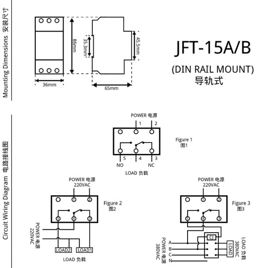
JFT-15A/B
Terminal introduction: PORT 1 and PORT 2 are power terminals; PORT 3 is normally closed terminal; PORT 4 is common terminal; PORT 5 is normally closed terminal Wiring diagram: If you need to control a single-phase normally closed load (LOAD1) and a single-phase normally open load (LOAD2), you can connect them as shown in Figure 2. If you need to control a three-phase load, you can connect it as shown in Figure 3.
JFT-15A/B dimensions and wiring diagram
Instructions For Use (How to set)
Please make sure that you have understood the functions of all the buttons on the panel (button area), and perform the actual operation according to the instructions.
1 Description of buttons and indicators
CLOCK (): Press to display your local time (it should be set by yourself: you can press and hold the "CLOCK" key to enter the "Time Adjustment Mode", and adjust the "WEEK", "HOUR", and "MINUTE" key to set the local time). PS: If no operation is performed within 30 seconds, the timer switch will automatically display the local time. TIMER(): Press to enter the "Editing Mode", and then set the time to switch the load by adjusting the "WEEK", "HOUR", and "MINUTE" key. WEEK (D+): Adjust week or day. There are various working modes, such as "Five-day Mode" (Monday to Friday), "Six-day Mode" (Monday to Saturday), "Weekend Mode" (Saturday, Sunday), "Daily Mode" (Monday to Sunday), and "Three-day Mode" (Mon-Wed-Fri; Tue-Thu-Sat; Mon-Tue-Wed; Thu-Fri-Sat). HOUR (H+): Adjust hour. MINUTE (M+): Adjust minute. AUTO/MANU (MANUAL): Switch the three switching mode of "ON", "AUTO" and "OFF". For multiple-output timer switches, the output combination can be configured through the "AUTO/MANU" key when in the "Editing Mode" RESET/RECALL (Cancel/Restore, C/R): Press to cancel or restore the timing setting. PS: For products with button lock function, press the " RESET/RECALL " key four times to lock or unlock all buttons. C: Long press the "C" key to clear all settings of the timer switch. POWER LED: When the Power LED (red) is on, it means that the timer switch has been successfully connected to the power source. WORK LED: When the Power LED (red) and the Work LED (green) are on at the same time, it means that the load is powered on.
2 Operating instructionsStep 1. Timing setting (on)
Press the " TIMER " button to enter the "Editing Mode". At this time, the "ON1" symbol will appear at the bottom left of the LCD screen (that is, the first time to turn on the load, as shown in Figure 4), and then press the "WEEK" to select Working Mode, and then press the "HOUR" and "MINUTE" keys to input the required switching on time.
Step 2. Timing setting (off)
Press the " TIMER " button again, the "1OFF" symbol will appear at the bottom left of the LCD screen (that is, the first time to turn off the load, as shown in Figure 5), and then press the "WEEK" to select Working Mode, and then press the "HOUR" and "MINUTE" keys to input the required switching off time. At this time, the first group of timing setting has been completed.

Timing Setting 1
Step 3. Timing setting (number of groups)
After completing the first group of timing setting, press the "TIMER" button again, the LCD display will show the "ON2" symbol, and you can set the second set of time setting. According to actual needs, you can repeat steps 1 and 2 to set many groups (the maximum programmable group number depends on the product's built-in chip). If you want to exit the "Editing Mode", you can press the "CLOCK" key to exit it.
Step 4. RESET/RECALL
After setting a group of time, for example, turn on the load at 18:30 every day (Figure 6), and turn off the load at 23:20 every day (Figure 7). If you want to cancel this group, you can press the "RESET/RECALL" button to delete this group of time settings. At this time, the group of time will be reset to the initial state, that is, "--: --" (Figure 4 and Figure 5). Under certain conditions (without any key operation or switching to other interfaces within 20 seconds after cancel operation), just press the "RESET/RECALL" button again to restore this group of time settings.
Step 5. AUTO/MANU
The timer switch has two switching modes: automatic and manual. In the automatic mode, the timer switch will be set according to the timing of steps 1 to 3, and the load will be automatically turned on or off at the corresponding time without human intervention. In manual mode, the load must be turned on or off by manual adjustment. The specific operations are as follows: 1) If you need to turn on the load manually, you can click the "AUTO/MANU" button to switch the "▼" symbol on the display to the "ON" position (Figure 8). At this time, the load will always be in the on state and cannot be turned off automatically. 2) If you need to turn off the load manually, you can click the "AUTO/MANU" button to switch the "▼" symbol on the display to the "OFF" position (Figure 9). At this time, the load will always be in the off state and cannot be turned on automatically. 3) If you need to switch the load automatically, you can click the "AUTO/MANU" button to switch the "▼" symbol on the display to the "AUTO" position (Figure 10). At this time, the working state of the load will be switching automatically according to the timing setting, without being interfered by humans.

Timing Setting 2
When you think there is a fault (FAQs)
Note: When the product fails, please disconnect the power first, and then check the equipment! 1 Check the week If the timer switch does not turn on or turn off the load at the set time, it may be that the "WEEK" is not adjusted correctly, please check or reset it according to the method introduced in "Timing Setting". 2 Check the time groups If the first point is confirmed to be correct, but the load still cannot be switched correctly on time, the reason will be that the extra time group has not been cancelled. Please refer to the method introduced in "Timing Setting" to delete it. PS: Only when the display shows "--: --", it means the time group is deleted successful; if it displays "00:00", it means 0 o'clock (24 o'clock), not the deleting success. 3 Check the switching mode If the above two points are confirmed to be correct, but the timer switch still does not work normally, it may be that the timer switch is working in "Manual Mode". You can first adjust the "AUTO/MANU" key to set the timer switch to the right working state of the load (ON or OFF), then switch to the "Automatic Mode". 4 Check the fuse If the above three points are correct and the timer switch still cannot work normally, please open the rear seat insurance cover (terminal cover) and check whether the fuse has been blown. If it is blown, please replace with a new 0.1A~0.3A fuse. 5 Check the power supply If the Work LED (or Output LED) is on when the timer switch is working, but the load cannot be switched normally, please check whether the voltage of the power supply is too low. If the timer switch is burned out, please check whether the power supply voltage exceeds the rated voltage of the product and whether the power cable is connected incorrectly. 6 Please replace the battery If the LCD screen does not display or the display is not clear, replace the battery with the same specification. (Only for timer switch with replaceable batteries) 7 Please contact us or local distributor If the fault cannot be eliminated by the above methods, please contact us or the distributor (dealer) in your local area.
Attentions
1 For those equipment (such as medical equipment and large equipment, etc.) that may cause life safety accidents or cause major harm to society due to the error of the timer switch, please do not choose this timer switch. 2 For those equipment (large heaters or cold storage, etc.) that may cause major property losses due to the error of the timer switch, ensure that there is sufficient design margin when using this timer switch, and take safeguard measures such as the double protection circuit. 3 Do not repair, disassemble or modify this timer switch by yourself. If you need to repair and check it, please be sure to entrust a dealership or other authorized unit. 4 Do not touch any terminal on the timer switch after it powered on. 5 This timer switch cannot work in humid, corrosive and high metal content gas environment. And do not let the timer switch come into contact with oil or water.
0 notes
Text
JFT-03 Series Digital Programmable Time Switch
JFT-03 SeriesDigital Programmable Time Switch
Introduction
JFT series digital programmable time-controlled switch can automatically turn on or off the power of various electrical equipment according to the time set by the user. JFT series microcomputer time-controlled switches are composed of LCD digital display, programmable IC chips, buttons, switch components, etc., which are widely used in street lights, neon lights, advertising signs, production equipment, assembly lines, broadcast equipment and other equipment. The JFT series time-controlled switch adopts a new patch technology, which can effectively avoid the phenomenon of false welding and missing welding, and has the characteristics of stable performance, low power consumption, and light weight. JFT-03 can be directly welded into the instrument, or be panel mounted with a contact bracket.
Parameters

JFT-03
Timer Range: 1min≤t≤168h (cycle work daily or weekly) Voltage: 110VAC, 220VAC/50Hz (or other customized voltage) Operation Temperature: -10℃~50℃ Operation Humidity: <95% Number of Settings: 10 groups per day Switching Capacity: 10A (resistive load) Contact Type:SPDT, 1 NO and 1 NC contact Battery: Built-in rechargeable Ni-MH battery Consumption Power: ≤5W Time Error: ≤2s/day (25℃) Weight:140g Dimensions: 48×48×96mm Mounting: Panel/Wall
Dimensions & Wiring Diagram
JFT-03
1 DC power supply (as shown in Figure 1)
2 Single-phase AC power supply 2.1 Direct control method (as shown in Figure 2.1) Applicable objects: Loads with single-phase power supply, and the power consumption does not exceed the rated switching capacity of the switch. 2.1 Single-phase expansion method (as shown in Figure 2.2) Applicable object: Load with single-phase power supply, but the power consumption exceeds the rated switching capacity of this switch. The capacity expansion method should be adopted for inductive loads.
3 Three-phase AC power supply (as shown in Figure 3) Need to connect a three-phase AC contactor (coil voltage is 220VAC/50HZ).

JFT-03 dimensions and wiring diagram
Instructions For Use (How to set)
Please make sure that you have understood the functions of all the buttons on the panel (button area), and perform the actual operation according to the instructions.
1 Description of buttons and indicators
CLOCK (): Press to display your local time (it should be set by yourself: you can press and hold the "CLOCK" key to enter the "Time Adjustment Mode", and adjust the "WEEK", "HOUR", and "MINUTE" key to set the local time). PS: If no operation is performed within 30 seconds, the timer switch will automatically display the local time. TIMER(): Press to enter the "Editing Mode", and then set the time to switch the load by adjusting the "WEEK", "HOUR", and "MINUTE" key. WEEK (D+): Adjust week or day. There are various working modes, such as "Five-day Mode" (Monday to Friday), "Six-day Mode" (Monday to Saturday), "Weekend Mode" (Saturday, Sunday), "Daily Mode" (Monday to Sunday), and "Three-day Mode" (Mon-Wed-Fri; Tue-Thu-Sat; Mon-Tue-Wed; Thu-Fri-Sat). HOUR (H+): Adjust hour. MINUTE (M+): Adjust minute. AUTO/MANU (MANUAL): Switch the three switching mode of "ON", "AUTO" and "OFF". For multiple-output timer switches, the output combination can be configured through the "AUTO/MANU" key when in the "Editing Mode" RESET/RECALL (Cancel/Restore, C/R): Press to cancel or restore the timing setting. PS: For products with button lock function, press the " RESET/RECALL " key four times to lock or unlock all buttons. C: Long press the "C" key to clear all settings of the timer switch. POWER LED: When the Power LED (red) is on, it means that the timer switch has been successfully connected to the power source. WORK LED: When the Power LED (red) and the Work LED (green) are on at the same time, it means that the load is powered on.
2 Operating instructionsStep 1. Timing setting (on)
Press the " TIMER " button to enter the "Editing Mode". At this time, the "1ON" symbol will appear at the bottom left of the LCD screen (that is, the first time to turn on the load, as shown in Figure 4), and then press the "WEEK" to select Working Mode, and then press the "HOUR" and "MINUTE" keys to input the required switching on time.
Step 2. Timing setting (off)
Press the " TIMER " button again, the "1OFF" symbol will appear at the bottom left of the LCD screen (that is, the first time to turn off the load, as shown in Figure 5), and then press the "WEEK" to select Working Mode, and then press the "HOUR" and "MINUTE" keys to input the required switching off time. At this time, the first group of timing setting has been completed.

Timing Setting 1
Step 3. Timing setting (number of groups)
After completing the first group of timing setting, press the "TIMER" button again, the LCD display will show the "2ON" symbol, and you can set the second set of time setting. According to actual needs, you can repeat steps 1 and 2 to set many groups (the maximum programmable group number depends on the product's built-in chip). If you want to exit the "Editing Mode", you can press the "CLOCK" key to exit it.
Step 4. RESET/RECALL
After setting a group of time, for example, turn on the load at 18:30 every day (Figure 6), and turn off the load at 23:20 every day (Figure 7). If you want to cancel this group, you can press the "RESET/RECALL" button to delete this group of time settings. At this time, the group of time will be reset to the initial state, that is, "--: --" (Figure 4 and Figure 5). Under certain conditions (without any key operation or switching to other interfaces within 20 seconds after cancel operation), just press the "RESET/RECALL" button again to restore this group of time settings.
Step 5. AUTO/MANU
The timer switch has two switching modes: automatic and manual. In the automatic mode, the timer switch will be set according to the timing of steps 1 to 3, and the load will be automatically turned on or off at the corresponding time without human intervention. In manual mode, the load must be turned on or off by manual adjustment. The specific operations are as follows: 1) If you need to turn on the load manually, you can click the "AUTO/MANU" button to switch the "▼" symbol on the display to the "ON" position (Figure 8). At this time, the load will always be in the on state and cannot be turned off automatically. 2) If you need to turn off the load manually, you can click the "AUTO/MANU" button to switch the "▼" symbol on the display to the "OFF" position (Figure 9). At this time, the load will always be in the off state and cannot be turned on automatically. 3) If you need to switch the load automatically, you can click the "AUTO/MANU" button to switch the "▼" symbol on the display to the "AUTO" position (Figure 10). At this time, the working state of the load will be switching automatically according to the timing setting, without being interfered by humans.

Timing Setting 2
When you think there is a fault (FAQs)
Note: When the product fails, please disconnect the power first, and then check the equipment! 1 Check the week If the timer switch does not turn on or turn off the load at the set time, it may be that the "WEEK" is not adjusted correctly, please check or reset it according to the method introduced in "Timing Setting". 2 Check the time groups If the first point is confirmed to be correct, but the load still cannot be switched correctly on time, the reason will be that the extra time group has not been cancelled. Please refer to the method introduced in "Timing Setting" to delete it. PS: Only when the display shows "--: --", it means the time group is deleted successful; if it displays "00:00", it means 0 o'clock (24 o'clock), not the deleting success. 3 Check the switching mode If the above two points are confirmed to be correct, but the timer switch still does not work normally, it may be that the timer switch is working in "Manual Mode". You can first adjust the "AUTO/MANU" key to set the timer switch to the right working state of the load (ON or OFF), then switch to the "Automatic Mode". 4 Check the fuse If the above three points are correct and the timer switch still cannot work normally, please open the rear seat insurance cover (terminal cover) and check whether the fuse has been blown. If it is blown, please replace with a new 0.1A~0.3A fuse. 5 Check the power supply If the Work LED (or Output LED) is on when the timer switch is working, but the load cannot be switched normally, please check whether the voltage of the power supply is too low. If the timer switch is burned out, please check whether the power supply voltage exceeds the rated voltage of the product and whether the power cable is connected incorrectly. 6 Please replace the battery If the LCD screen does not display or the display is not clear, replace the battery with the same specification. (Only for timer switch with replaceable batteries) 7 Please contact us or local distributor If the fault cannot be eliminated by the above methods, please contact us or the distributor (dealer) in your local area.
Attentions
1 For those equipment (such as medical equipment and large equipment, etc.) that may cause life safety accidents or cause major harm to society due to the error of the timer switch, please do not choose this timer switch. 2 For those equipment (large heaters or cold storage, etc.) that may cause major property losses due to the error of the timer switch, ensure that there is sufficient design margin when using this timer switch, and take safeguard measures such as the double protection circuit. 3 Do not repair, disassemble or modify this timer switch by yourself. If you need to repair and check it, please be sure to entrust a dealership or other authorized unit. 4 Do not touch any terminal on the timer switch after it powered on. 5 This timer switch cannot work in humid, corrosive and high metal content gas environment. And do not let the timer switch come into contact with oil or water.
0 notes
Text
JFT-02 Digital Programable Time Switch (DIN Rail Mount)
Introduction
JFT02 series microcomputer time control switch is specially designed for DIN Rail Mount installation. It can be directly installed into the power distribution cabinet, meter box, signal box, etc., and used with other electrical equipment to achieve efficient control of the load JFT02 series digital time-controlled switch is consisted of digital LCD display, programmable IC chip, buttons, switching components and etc. JFT02 series digital timer switch is widely used in street lights, neon lights, advertising signs, production equipment, assembly lines, and broadcast equipment. The new version JFT02 adopts a brand-new chip technology, which can effectively avoid the false welding and missing welding. Besides, the all-new designed JFT02 has the characteristics of stable performance, low power consumption, light weight, and etc. The JFT02 series has two sub-series. JFT02-1a adopts single pole single throw switching plan (SPST), with only one normally open contact, which can control the switching state of a load; JFT02-1c adopts double pole double throw switching plan (SPDT), which has One normally open contact and one normally closed contact can simultaneously control the switching state of two loads.
Parameters

JFT02 (DIN Rail Mount)
Timer Range: 1min≤t≤168h (cycle work daily or weekly) Operation Voltage: 110VAC, 220VAC/50Hz (or other customized voltage) Operation Temperature: -10℃~ 60℃ Operation Humidity: <95% Switching Capacity: 30A (resistive load), 15A (inductive load) Contact Type: JFT02-1a (SPST, only 1 NO contact); JFT02-1c (SPDT, 1 NO and 1 NC contact) Number of Settings: 10 groups per day Control Mode: Manual, Auto Consumption Power: ≤5W Battery: 8AA battery Time Error: ≤2s/day (25℃) Dimensions: 100×50×74mm Mounting: Wall/Rail
Dimensions & Wiring Diagram
JFT02 (DIN Rail Mount)
JFT02 has two sub-series (as shown in Figure 1): JFT02-1a has one normally open contact (PORT4); JFT02-1c has one normally open contact (PORT4) and one normally closed contact (PORT5).
1 Single Phase Power Supply 1.1 Direct control method (as shown in Figure 2) Applicable objects: Loads with single-phase power supply, and the power consumption does not exceed the rated switching capacity of the timer switch. 1.2 Single-phase expansion method Applicable objects: load with single-phase power supply, but the power consumption exceeds the rated switching capacity of the timer switch. This method should be adopted for inductive loads. If this wiring method is adopted, the output terminal of the digital timer switch needs to be connected to a single phase AC contactor whose switching capacity should larger than the power consumption of the load to expanse the switching capacity of the timer switch.
2 Three Phase Power Supply Applicable objects: load with three-phase power supply (as shown in Figure 3).

JFT02 dimensions and wiring diagram
Instructions For Use (How to set)
Please make sure that you have understood the functions of all the buttons on the panel (button area), and perform the actual operation according to the instructions.
1 Description of buttons and indicators
CLOCK (): Press to display your local time (it should be set by yourself: you can press and hold the "CLOCK" key to enter the "Time Adjustment Mode", and adjust the "WEEK", “HOUR”, and “MINUTE” key to set the local time). PS: If no operation is performed within 30 seconds, the timer switch will automatically display the local time. TIMER(): Press to enter the "Editing Mode", and then set the time to switch the load by adjusting the "WEEK", “HOUR”, and “MINUTE” key. WEEK (D+): Adjust week or day. There are various working modes, such as "Five-day Mode" (Monday to Friday), "Six-day Mode" (Monday to Saturday), "Weekend Mode" (Saturday, Sunday), “Daily Mode" (Monday to Sunday), and "Three-day Mode" (Mon-Wed-Fri; Tue-Thu-Sat; Mon-Tue-Wed; Thu-Fri-Sat). HOUR (H+): Adjust hour. MINUTE (M+): Adjust minute. AUTO/MANU (MANUAL): Switch the three switching mode of "ON", "AUTO" and "OFF". For multiple-output timer switches, the output combination can be configured through the "AUTO/MANU" key when in the "Editing Mode" RESET/RECALL (Cancel/Restore, C/R): Press to cancel or restore the timing setting. PS: For products with button lock function, press the " RESET/RECALL " key four times to lock or unlock all buttons. C: Long press the "C" key to clear all settings of the timer switch. POWER LED: When the Power LED (red) is on, it means that the timer switch has been successfully connected to the power source. WORK LED: When the Power LED (red) and the Work LED (green) are on at the same time, it means that the load is powered on.
2 Operating instructionsStep 1. Timing setting (on)
Press the " TIMER " button to enter the "Editing Mode". At this time, the "1ON" symbol will appear at the bottom left of the LCD screen (that is, the first time to turn on the load, as shown in Figure 4), and then press the "WEEK" to select Working Mode, and then press the "HOUR" and "MINUTE" keys to input the required switching on time.
Step 2. Timing setting (off)
Press the " TIMER " button again, the "1OFF" symbol will appear at the bottom left of the LCD screen (that is, the first time to turn off the load, as shown in Figure 5), and then press the "WEEK" to select Working Mode, and then press the "HOUR" and "MINUTE" keys to input the required switching off time. At this time, the first group of timing setting has been completed.

Timing Setting1
Step 3. Timing setting (number of groups)
After completing the first group of timing setting, press the "TIMER" button again, the LCD display will show the "2ON" symbol, and you can set the second set of time setting. According to actual needs, you can repeat steps 1 and 2 to set many groups (the maximum programmable group number depends on the product's built-in chip). If you want to exit the “Editing Mode”, you can press the "CLOCK" key to exit it.
Step 4. RESET/RECALL
After setting a group of time, for example, turn on the load at 18:30 every day (Figure 6), and turn off the load at 23:20 every day (Figure 7). If you want to cancel this group, you can press the "RESET/RECALL" button to delete this group of time settings. At this time, the group of time will be reset to the initial state, that is, "--: --" (Figure 4 and Figure 5). Under certain conditions (without any key operation or switching to other interfaces within 20 seconds after cancel operation), just press the "RESET/RECALL" button again to restore this group of time settings.
Step 5. AUTO/MANU
The timer switch has two switching modes: automatic and manual. In the automatic mode, the timer switch will be set according to the timing of steps 1 to 3, and the load will be automatically turned on or off at the corresponding time without human intervention. In manual mode, the load must be turned on or off by manual adjustment. The specific operations are as follows: 1) If you need to turn on the load manually, you can click the "AUTO/MANU" button to switch the "▼" symbol on the display to the "ON" position (Figure 8). At this time, the load will always be in the on state and cannot be turned off automatically. 2) If you need to turn off the load manually, you can click the "AUTO/MANU" button to switch the "▼" symbol on the display to the "OFF" position (Figure 9). At this time, the load will always be in the off state and cannot be turned on automatically. 3) If you need to switch the load automatically, you can click the "AUTO/MANU" button to switch the "▼" symbol on the display to the "AUTO" position (Figure 10). At this time, the working state of the load will be switching automatically according to the timing setting, without being interfered by humans.

Timing Setting2
When you think there is a fault (FAQs)
Note: When the product fails, please disconnect the power first, and then check the equipment! 1 Check the week If the timer switch does not turn on or turn off the load at the set time, it may be that the "WEEK" is not adjusted correctly, please check or reset it according to the method introduced in "Timing Setting". 2 Check the time groups If the first point is confirmed to be correct, but the load still cannot be switched correctly on time, the reason will be that the extra time group has not been cancelled. Please refer to the method introduced in "Timing Setting" to delete it. PS: Only when the display shows "--: --", it means the time group is deleted successful; if it displays "00:00", it means 0 o'clock (24 o'clock), not the deleting success. 3 Check the switching mode If the above two points are confirmed to be correct, but the timer switch still does not work normally, it may be that the timer switch is working in "Manual Mode". You can first adjust the "AUTO/MANU" key to set the timer switch to the right working state of the load (ON or OFF), then switch to the "Automatic Mode". 4 Check the fuse If the above three points are correct and the timer switch still cannot work normally, please open the rear seat insurance cover (terminal cover) and check whether the fuse has been blown. If it is blown, please replace with a new 0.1A~0.3A fuse. 5 Check the power supply If the Work LED (or Output LED) is on when the timer switch is working, but the load cannot be switched normally, please check whether the voltage of the power supply is too low. If the timer switch is burned out, please check whether the power supply voltage exceeds the rated voltage of the product and whether the power cable is connected incorrectly. 6 Please replace the battery If the LCD screen does not display or the display is not clear, replace the battery with the same specification. (Only for timer switch with replaceable batteries) 7 Please contact us or local distributor If the fault cannot be eliminated by the above methods, please contact us or the distributor (dealer) in your local area.
Attentions
1 For those equipment (such as medical equipment and large equipment, etc.) that may cause life safety accidents or cause major harm to society due to the error of the timer switch, please do not choose this timer switch. 2 For those equipment (large heaters or cold storage, etc.) that may cause major property losses due to the error of the timer switch, ensure that there is sufficient design margin when using this timer switch, and take safeguard measures such as the double protection circuit. 3 Do not repair, disassemble or modify this timer switch by yourself. If you need to repair and check it, please be sure to entrust a dealership or other authorized unit. 4 Do not touch any terminal on the timer switch after it powered on. 5 This timer switch cannot work in humid, corrosive and high metal content gas environment. And do not let the timer switch come into contact with oil or water.
0 notes
Text
KG316T Series (Multiple Output) Digital Programable Timer Switch (Multiple Output)
Introduction
KG316T series timer switch can automatically turn on or off the power of various electrical equipment according to the time set by the user. KG316T series digital time-controlled switch is consisted of digital LCD display, programmable IC chip, buttons, switching components and etc. KG316T series microcomputer timer switch is widely used in street lights, neon lights, advertising signs, production equipment, assembly lines, and broadcast equipment. The new version KG316T adopts a brand-new chip technology, which can effectively avoid the false welding and missing welding. Besides, the all-new designed KG316T has the characteristics of stable performance, low power consumption, light weight, and replaceable power supply battery. KG316T series multiple outputs type timer switch has multiple sets of independent output terminals, which can efficiently control multiple loads without interfering with each other. KG316T series multiple output timer switch is suitable for equipment that has limited installation space but needs to control multiple loads. KG316T (multiple output) has two sub-series, KG316T-2a can control the working status of two independent loads, and KG316T-3a can control the working status of three independent loads.
Parameters
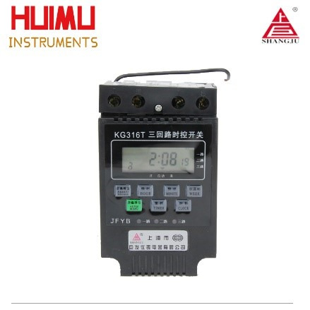
KG316T (Multiple Output)
Timer Range: 1min≤t≤168h (cycle work daily or weekly) Operation Voltage: AC220V/50Hz (or other customized voltage) Operation Temperature: -10℃~ 50℃ Operation Humidity:<95% Switching Capacity: 10A per output (resistive load) Number of Outputs: KG316T-2a (max two outputs), KG316T-3a (max three outputs); Each output is independent of each other and does not interfere with each other. Number of Settings: 16 groups per output, with anti-mistouch button lock Control Mode: Manual, Auto Consumption Power: ≤4W Battery: 5AA battery Time Error: ≤2s/day (25℃) Weight: 450g Dimensions: 120×74×58mm Mounting: Wall/Rail
Dimensions & Wiring Diagram
KG316T (Multiple Output)
1 Direct control method (as shown in Figure 1) Applicable objects: Loads with single-phase power supply, and the power consumption does not exceed the rated switching capacity of the timer switch. 2 Single-phase expansion method (as shown in Figure 2) Applicable objects: load with single-phase power supply, but the power consumption exceeds the rated switching capacity of the timer switch. This method should be adopted for inductive loads. If this wiring method is adopted, the output terminal of the digital timer switch needs to be connected to a single phase AC contactor whose switching capacity should larger than the power consumption of the load to expanse the switching capacity of the timer switch. For example, Figure 2.1 shows how to expand the switching capacity of OUT2 of KG316T-2a, and Figure 2.2 shows how to expand the switching capacity of OUT3 of KG316T-3a. *Note: Each load of this product and the power supply share a neutral line. Please make sure not to connect it wrongly when wiring.

KG316T (multiple output) dimensions and wiring diagram
Instructions For Use (How to set)
Please make sure that you have understood the functions of all the buttons on the panel (button area), and perform the actual operation according to the instructions.
1 Description of buttons and indicators
CLOCK (): Press to display your local time (it should be set by yourself: you can press and hold the "CLOCK" key to enter the "Time Adjustment Mode", and adjust the "WEEK", "HOUR", and "MINUTE" key to set the local time). PS: If no operation is performed within 30 seconds, the timer switch will automatically display the local time. TIMER(): Press to enter the "Editing Mode", and then set the time to switch the load by adjusting the "WEEK", "HOUR", and "MINUTE" key. WEEK (D+): Adjust week or day. There are various working modes, such as "Five-day Mode" (Monday to Friday), "Six-day Mode" (Monday to Saturday), "Weekend Mode" (Saturday, Sunday), "Daily Mode" (Monday to Sunday), and "Three-day Mode" (Mon-Wed-Fri; Tue-Thu-Sat; Mon-Tue-Wed; Thu-Fri-Sat). HOUR (H+): Adjust hour. MINUTE (M+): Adjust minute. AUTO/MANU (MANUAL): Switch the three switching mode of "ON", "AUTO" and "OFF". For multiple-output timer switches, the output combination can be configured through the "AUTO/MANU" key when in the "Editing Mode" RESET/RECALL (Cancel/Restore, C/R): Press to cancel or restore the timing setting. PS: For products with button lock function, press the " RESET/RECALL " key four times to lock or unlock all buttons. C: Long press the "C" key to clear all settings of the timer switch. POWER LED: When the Power LED (red) is on, it means that the timer switch has been successfully connected to the power source. WORK LED: When the Power LED (red) and the Work LED (green) are on at the same time, it means that the load is powered on.
2 Operating instructionsStep 1. Timing setting (on)
Press the " TIMER " button to enter the "Editing Mode". At this time, the "1ON" symbol will appear at the bottom left of the LCD screen (that is, the first time to turn on the load, as shown in Figure 3), and then press the "WEEK" to select Working Mode, and then press the "HOUR" and "MINUTE" keys to input the required switching on time.
Step 2. Timing setting (off)
Press the " TIMER " button again, the "1OFF" symbol will appear at the bottom left of the LCD screen (that is, the first time to turn off the load, as shown in Figure 4), and then press the "WEEK" to select Working Mode, and then press the "HOUR" and "MINUTE" keys to input the required switching off time. At this time, the first group of timing setting has been completed.

Timing Setting1
Step 3. Timing setting (output combination)
For multiple-output timer switches, the output combination can be configured through the "AUTO/MANU" key when in the "Editing Mode" (as shown in Figure 7). KG316T-2a has three output combinations (OUT1, OUT2, OUT1-OUT2); KG316T-3a has six output combinations (OUT1, OUT2, OUT3, OUT1-OUT2, OUT1-OUT3, OUT1-OUT2-OUT3, OUT2-OUT3). Take KG316T-3a as an example. If you want LOAD 2 to turn on at 10 o'clock AM, you can set it according to Figure 8; if you want LOAD1 and LOAD 3 to turn off at 6 o'clock PM, you can set it according to Figure 9.

Timing Setting2
Step 4. Timing setting (number of groups)
After completing the first group of timing setting, press the "TIMER" button again, the LCD display will show the "2ON" symbol, and you can set the second set of time setting. According to actual needs, you can repeat steps 1 to 3 to set many groups (the maximum programmable group number depends on the product's built-in chip). If you want to exit the "Editing Mode", you can press the "CLOCK" key to exit it.
Step 5. RESET/RECALL
After setting a group of time, for example, turn on the LOAD1 at 18:30 every day (Figure 5), and turn off the LOAD1 at 23:20 every day (Figure 6). If you want to cancel this group, you can press the "RESET/RECALL" button to delete this group of time settings. At this time, the group of time will be reset to the initial state, that is, "--: --" (Figure 3 and Figure 4). Under certain conditions (without any key operation or switching to other interfaces within 20 seconds after cancel operation), just press the "RESET/RECALL" button again to restore this group of time settings.
Step 6. AUTO/MANU
The timer switch has two switching modes: automatic and manual. In the automatic mode, the timer switch will be set according to the timing of steps 1 to 4, and the load will be automatically turned on or off at the corresponding time without human intervention. In manual mode, the load must be turned on or off by manual adjustment. The specific operations are as follows: 1) If you need to turn on the load manually, you can click the "AUTO/MANU" button to switch the "▼" symbol on the display to the "ON" position (Figure 10). At this time, the load will always be in the on state and cannot be turned off automatically. 2) If you need to turn off the load manually, you can click the "AUTO/MANU" button to switch the "▼" symbol on the display to the "OFF" position (Figure 11). At this time, the load will always be in the off state and cannot be turned on automatically. 3) If you need to switch the load automatically, you can click the "AUTO/MANU" button to switch the "▼" symbol on the display to the "AUTO" position (Figure 12). At this time, the working state of the load will be switching automatically according to the timing setting, without being interfered by humans.

Timing Setting3
Step 7. Lock and unlock
For the timer switch with button lock (or keyboard lock), you can quick press the "RESET/RECALL" key four times to lock or unlock all the buttons. -How to lock the buttons? In the unlocked state, quick press the "RESET/RECALL" button four times or without any operation within 30 seconds to lock all the buttons (Figure 13). At this time, there will be a "∂" symbol in the bottom left, and you cannot make any settings for the timer switch. -How to unlock buttons? In the locked state, quick press the "RESET/RECALL" button four times to unlock all the buttons (Figure 14), and you can make settings at this time.
When you think there is a fault (FAQs)
Note: When the product fails, please disconnect the power first, and then check the equipment! 1 Check the week If the timer switch does not turn on or turn off the load at the set time, it may be that the "WEEK" is not adjusted correctly, please check or reset it according to the method introduced in "Timing Setting". 2 Check the time groups If the first point is confirmed to be correct, but the load still cannot be switched correctly on time, the reason will be that the extra time group has not been cancelled. Please refer to the method introduced in "Timing Setting" to delete it. PS: Only when the display shows "--: --", it means the time group is deleted successful; if it displays "00:00", it means 0 o'clock (24 o'clock), not the deleting success. 3 Check the switching mode If the above two points are confirmed to be correct, but the timer switch still does not work normally, it may be that the timer switch is working in "Manual Mode". You can first adjust the "AUTO/MANU" key to set the timer switch to the right working state of the load (ON or OFF), then switch to the "Automatic Mode". 4 Check the fuse If the above three points are correct and the timer switch still cannot work normally, please open the rear seat insurance cover (terminal cover) and check whether the fuse has been blown. If it is blown, please replace with a new 0.1A~0.3A fuse. 5 Check the power supply If the Work LED (or Output LED) is on when the timer switch is working, but the load cannot be switched normally, please check whether the voltage of the power supply is too low. If the timer switch is burned out, please check whether the power supply voltage exceeds the rated voltage of the product and whether the power cable is connected incorrectly. 6 Please replace the battery If the LCD screen does not display or the display is not clear, replace the battery with the same specification. (Only for timer switch with replaceable batteries) 7 Please contact us or local distributor If the fault cannot be eliminated by the above methods, please contact us or the distributor (dealer) in your local area.
Attentions
1 For those equipment (such as medical equipment and large equipment, etc.) that may cause life safety accidents or cause major harm to society due to the error of the timer switch, please do not choose this timer switch. 2 For those equipment (large heaters or cold storage, etc.) that may cause major property losses due to the error of the timer switch, ensure that there is sufficient design margin when using this timer switch, and take safeguard measures such as the double protection circuit. 3 Do not repair, disassemble or modify this timer switch by yourself. If you need to repair and check it, please be sure to entrust a dealership or other authorized unit. 4 Do not touch any terminal on the timer switch after it powered on. 5 This timer switch cannot work in humid, corrosive and high metal content gas environment. And do not let the timer switch come into contact with oil or water.
0 notes
Text
KG316T Series (Single Output) Digital Programable Timer Switch (Single Output)
Introduction
KG316T series timer switch can automatically turn on or off the power of various electrical equipment according to the time set by the user. KG316T series digital time-controlled switch is consisted of digital LCD display, programmable IC chip, buttons, switching components and etc. KG316T series microcomputer timer switch is widely used in street lights, neon lights, advertising signs, production equipment, assembly lines, and broadcast equipment. The new version KG316T adopts a brand-new chip technology, which can effectively avoid the false welding and missing welding. Besides, the all-new designed KG316T has the characteristics of stable performance, low power consumption, light weight, and replaceable power supply battery. The function of KG316T-D series timer switch is similar to that of KG316T, but it adopts the wiring method of lower wiring. KG316T-Ⅱ series timer switch (mini size type) is an improved version of KG316T, and KG316T-Ⅱ has a smaller size and is suitable for applications that have higher requirements for installation space. KG316T-Ⅱ has a built-in nickel-hydrogen rechargeable battery to prevent the battery from running out if the battery cannot be replaced in time.
Parameters

KG316T (Single Output, Upper Wire)

Timer Range: 1min≤t≤168h (cycle work daily or weekly) Operation Voltage: AC220V/50Hz (or other customized voltage) Operation Temperature: -10℃~ 60℃ Operation Humidity:<95% Switching Capacity: 25A (resistive load); 20A (inductive load) Number of Settings: 10/16 groups per day, with anti-mistouch button lock Control Mode: Manual, Auto Consumption Power: ≤1W Battery: 7AA battery Time Error: ≤1s/day (25℃) Weight: 260g Dimensions: 120×74×58mm Mounting: Wall/Rail
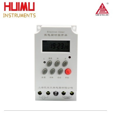
KG316T-D (Single Output, Down Wire)
Timer Range: 1min≤t≤168h (cycle work daily or weekly) Operation Voltage: AC220V/50Hz (or other customized voltage) Operation Temperature: -10℃~ 60℃ Operation Humidity:<95% Rated Current: 3A(220V), 1.9A(380V) Load Power: 6KW (resistive load), 1.8KW (inductive load), 1.2KW (electric motor), 0.9KW (light) Switching Capacity: 25A (resistive load); 20A (inductive load) Number of Settings: 16 groups per day, with anti-mistouch button lock Consumption Power: ≤2W Battery: 5AA battery Time Error: ≤2s/day (25℃) Weight: 260g Dimensions: 120×77×53mm Mounting: Wall/Rail
KG316T-Ⅱ (Single Output, Mini Size)
Timer Range: 1min≤t≤168h (cycle work daily or weekly) Operation Voltage: AC220V/50Hz (or other customized voltage) Operation Temperature: -10℃~ 60℃ Operation Humidity:<95% Rated Power: 2.5KW Switching Capacity: 25A (resistive load); 20A (inductive load) Number of Settings: 16 groups per day Consumption Power: ≤2W Battery: Ni-MH rechargeable battery (1.2V, 40mAh) Time Error: ≤1s/day (25℃) Dimensions: 98×55×40mm Weight: 66g Mounting: Wall/Rail
Dimensions & Wiring Diagram
KG316T (Single Output, Upper Wire)
1 Single-phase power supply (there are two wiring methods) 1.1 Direct control method (as shown in Figure 1) Applicable objects: Loads with single-phase power supply, and the power consumption does not exceed the rated capacity of the switch (resistive load 25A, inductive load 20A). 1.2 Single-phase expansion method (as shown in Figure 2) Applicable objects: load with single-phase power supply, but the power consumption exceeds the rated capacity of the switch (resistive load 25A, inductive load 20A). If this wiring method is adopted, the output terminal of the digital timer switch needs to be connected to a single phase AC contactor whose load capacity should larger than the power consumption of the load to expanse the switching capacity of the timer switch. 2 Three-phase power supply (requires an external three-phase AC contactor) Applicable objects: Loads with three-phase power supply. If the coil voltage of the three-phase AC contactor is AC220V/50Hz, the wiring method shown in Figure 3. If the coil voltage of the three-phase AC contactor is AC380V/50Hz, the wiring method shown in Figure 4.

KG316T (single circuit, upper wiring) dimensions and wiring diagram
KG316T-D (Single Output, Down Wire)
There are two wiring methods for KG16T-D series, you can choose according to your needs.

KG316T-D (single circuit, down wiring) dimensions and wiring diagram

KG316T-Ⅱ(Single Output, Mini Size)
There are two wiring methods for KG16T-Ⅱ series, you can choose according to your needs.
KG316T-Ⅱ (single circuit, mini size) dimensions and wiring diagram
Instructions For Use (How to set)
Please make sure that you have understood the functions of all the buttons on the panel (button area), and perform the actual operation according to the instructions.
1 Description of buttons and indicators:
CLOCK (): Press to display your local time (it should be set by yourself: you can press and hold the "CLOCK" key to enter the "Time Adjustment Mode", and adjust the "WEEK", "HOUR", and "MINUTE" key to set the local time). PS: If no operation is performed within 30 seconds, the timer switch will automatically display the local time. TIMER (): Press to enter the "Editing Mode", and then set the time to switch the load by adjusting the "WEEK", "HOUR", and "MINUTE" key. WEEK (D+): Adjust week or day. There are various working modes, such as "Five-day Mode" (Monday to Friday), "Six-day Mode" (Monday to Saturday), "Weekend Mode" (Saturday, Sunday), "Daily Mode" (Monday to Sunday), and "Three-day Mode" (Mon-Wed-Fri; Tue-Thu-Sat; Mon-Tue-Wed; Thu-Fri-Sat). HOUR (H+): Adjust hour. MINUTE (M+): Adjust minute. AUTO/MANU (MANUAL): Switch the three switching mode of "ON", "AUTO" and "OFF". RESET/RECALL (Cancel/Restore, C/R): Press to cancel or restore the timing setting. PS: For products with button lock function, press the " RESET/RECALL " key four times to lock or unlock all buttons. C: Long press the "C" key to clear all settings of the timer switch. POWER LED: When the Power LED (red) is on, it means that the timer switch has been successfully connected to the power source. WORK LED: When the Power LED (red) and the Work LED (green) are on at the same time, it means that the load is powered on.
2 Operating instructions:Step 1. Timing setting (on):
Press the " TIMER " button to enter the "Editing Mode". At this time, the "1ON" symbol will appear at the bottom left of the LCD screen (that is, the first time to turn on the load, as shown in Figure 9), and then press the "WEEK" to select Working Mode, and then press the "HOUR" and "MINUTE" keys to input the required switching on time.
Step 2. Timing setting (off):
Press the " TIMER " button again, the "1OFF" symbol will appear at the bottom left of the LCD screen (that is, the first time to turn off the load, as shown in Figure 10), and then press the "WEEK" to select Working Mode, and then press the "HOUR" and "MINUTE" keys to input the required switching off time. At this time, the first group of timing setting has been completed.
Step 3. Timing setting (number of groups):
After completing the first group of timing setting, press the "TIMER" button again, the LCD display will show the "2ON" symbol, and you can set the second set of time setting. According to actual needs, you can repeat steps 1 and 2 to set many groups (the maximum programmable group number depends on the product's built-in chip). If you want to exit the "Editing Mode", you can press the "CLOCK" key to exit it.

Timing Setting1
Step 4. RESET/RECALL:
After setting a group of time, for example, turn on the load at 18:30 every day (Figure 11), and turn off the load at 23:20 every day (Figure 12). If you want to cancel this group, you can press the "RESET/RECALL" button to delete this group of time settings. At this time, the group of time will be reset to the initial state, that is, "--: --" (Figure 9 and Figure 10). Under certain conditions (without any key operation or switching to other interfaces within 20 seconds after cancel operation), just press the "RESET/RECALL" button again to restore this group of time settings.
Step 5. AUTO/MANU:
The timer switch has two switching modes: automatic and manual. In the automatic mode, the timer switch will be set according to the timing of steps 1 to 3, and the load will be automatically turned on or off at the corresponding time without human intervention. In manual mode, the load must be turned on or off by manual adjustment. The specific operations are as follows: 1) If you need to turn on the load manually, you can click the "AUTO/MANU" button to switch the "▼" symbol on the display to the "ON" position (Figure 13). At this time, the load will always be in the on state and cannot be turned off automatically. 2) If you need to turn off the load manually, you can click the "AUTO/MANU" button to switch the "▼" symbol on the display to the "OFF" position (Figure 14). At this time, the load will always be in the off state and cannot be turned on automatically. 3) If you need to switch the load automatically, you can click the "AUTO/MANU" button to switch the "▼" symbol on the display to the "AUTO" position (Figure 15). At this time, the working state of the load will be switching automatically according to the timing setting, without being interfered by humans.

Timing Setting2
Step 6. Lock and unlock:
For the timer switch with button lock (or keyboard lock), you can quick press the "RESET/RECALL" key four times to lock or unlock all the buttons. -How to lock the buttons? In the unlocked state, quick press the "RESET/RECALL" button four times or without any operation within 30 seconds to lock all the buttons (Figure 16). At this time, there will be a "∂" symbol in the bottom left, and you cannot make any settings for the timer switch. -How to unlock buttons? In the locked state, quick press the "RESET/RECALL" button four times to unlock all the buttons (Figure 17), and you can make settings at this time.
When you think there is a fault (FAQs)
Note: When the product fails, please disconnect the power first, and then check the equipment! 1 Check the week If the timer switch does not turn on or turn off the load at the set time, it may be that the "WEEK" is not adjusted correctly, please check or reset it according to the method introduced in "Timing Setting". 2 Check the time groups If the first point is confirmed to be correct, but the load still cannot be switched correctly on time, the reason will be that the extra time group has not been cancelled. Please refer to the method introduced in "Timing Setting" to delete it. PS: Only when the display shows "--: --", it means the time group is deleted successful; if it displays "00:00", it means 0 o'clock (24 o'clock), not the deleting success. 3 Check the switching mode If the above two points are confirmed to be correct, but the timer switch still does not work normally, it may be that the timer switch is working in "Manual Mode". You can first adjust the "AUTO/MANU" key to set the timer switch to the right working state of the load (ON or OFF), then switch to the "Automatic Mode". 4 Check the fuse If the above three points are correct and the timer switch still cannot work normally, please open the rear seat insurance cover (terminal cover) and check whether the fuse has been blown. If it is blown, please replace with a new 0.1A~0.3A fuse. 5 Check the power supply If the Work LED (or Output LED) is on when the timer switch is working, but the load cannot be switched normally, please check whether the voltage of the power supply is too low. If the timer switch is burned out, please check whether the power supply voltage exceeds the rated voltage of the product and whether the power cable is connected incorrectly. 6 Please replace the battery If the LCD screen does not display or the display is not clear, replace the battery with the same specification. (Only for timer switch with replaceable batteries) 7 Please contact us or local distributor If the fault cannot be eliminated by the above methods, please contact us or the distributor (dealer) in your local area.
Attentions
1 For those equipment (such as medical equipment and large equipment, etc.) that may cause life safety accidents or cause major harm to society due to the error of the timer switch, please do not choose this timer switch. 2 For those equipment (large heaters or cold storage, etc.) that may cause major property losses due to the error of the timer switch, ensure that there is sufficient design margin when using this timer switch, and take safeguard measures such as the double protection circuit. 3 Do not repair, disassemble or modify this timer switch by yourself. If you need to repair and check it, please be sure to entrust a dealership or other authorized unit. 4 Do not touch any terminal on the timer switch after it powered on. 5 This timer switch cannot work in humid, corrosive and high metal content gas environment. And do not let the timer switch come into contact with oil or water.
0 notes
Text
What are the types of timer switches?

Time-controlled switches can be divided into many types according to appearance, wiring method, function, etc. The common classification methods and our corresponding timer switch models are listed below.
1. According to the wiring method
-Upper wiring: KG316-3, KG316T, KG316T-2a, KG316T-3a -Lower wiring: KG316Y-G, JFT series, KG316T-Ⅱ, KG316T-D, JFT02, JFT-16/17 series, CN series
2. According to the controlled load quantity
-A: KG316-3, KG316Y-G, AS series, GUK series, KGF series -Multiple: JFT series, KG316T-2a, KG316T-3a, JFT02, JFT-16/17 series
3. According to the sensor type
-No sensor: KG316T (single loop), KG316T (multi loop) -Light sensor: KG316-3, AS series, GUK series, KGF series -Rain sensor: KG316Y-G
4. According to whether the latitude and longitude calculation system is built-in
-Yes: JFT-6, JFT-9
5. According to the installation method
-Panel type: JFT03, CN series -Rail type: JFT02, JFT-15A/B series, JFT-16/17 series -Wall-mounted type: KG316T
0 notes
Text
What should be paid attention to when using the timer switch?

If you cannot use the time-controlled switch reasonably and compliantly, it may cause you unnecessary economic losses. Before using the timer switch, you must pay attention to the following points: 1. For those equipment (such as medical equipment and large equipment, etc.) that may cause life safety accidents or cause major harm to society due to the error of the timer switch, please do not choose this timer switch. 2. For those equipment (large heaters or cold storage, etc.) that may cause major property losses due to the error of the timer switch, ensure that there is sufficient design margin when using this timer switch, and take safeguard measures such as the double protection circuit. 3. Do not repair, disassemble or modify this timer switch by yourself. If you need to repair and check it, please be sure to entrust a dealership or other authorized unit. 4. Do not touch any terminal on the timer switch after it powered on. 5. This timer switch cannot work in humid, corrosive and high metal content gas environment. And do not let the timer switch come into contact with oil or water.
0 notes