
Don't wanna be here? Send us removal request.
Statistics
We looked inside some of the posts by industrymachinetools and here's what we found interesting.
Average Info
Notes Per Post
1
Likes Per Post
1
Reblog Per Post
0
Reply Per Post
0
Time Between Posts
1 month
Number of Posts By Type
Text
17
Last Seen Tumblr Blogs


Fun Fact
Forty percent of Tumblr users are between the ages of 18 to 25.
Text
Redefining Precision in Pipeline Maintenance with TRITORC’s TTCB Machines
Achieving precise pipe cuts and weld preparations is of prime importance in pipeline maintenance. Traditional methods often fall short, especially when dealing with pipes in constrained spaces with complex geometries. Tritorc introduces its Pipe Cutting and Bevelling Machines (TTCB) that cover a range from 6-48 inches, revolutionizing the approach to these demanding tasks.
Ergonomic Design for Optimal Performance
Tritorc's TTCB series combines ergonomic design with great functionality, ensuring smooth operation even in the most challenging environments. With a diverse range of drive options - including Pneumatic, Electric, Servo Motor, and Hydraulic - these machines offer unmatched adaptability to various working conditions.
Safety-First Technology for Hazard-Free Operation
Safety is at the forefront of Tritorc's design philosophy. The TTCB machines feature spark-free, cold-cutting technology, eliminating the risks associated with traditional cutting methods. Fully enclosed bearings further enhance safety and durability, providing operators with peace of mind during operation.
Precision Engineering for Accurate Results
Precision is non-negotiable when it comes to pipe cutting, and Tritorc's TTCB machines deliver on this front. A strong and stable platform ensures accuracy in cutting dimensions, while the split frame construction allows for easy access to tight spaces. That facilitates efficient work even in challenging environments.
Tritorc's TTCB machines offer superior finishes compared to conventional cutting methods. The cold-cutting technology ensures pristine cuts, essential for smooth welding preparations. Whether it's gas cutting, plasma cutting, or angle grinder cutting, Tritorc's machines set a new standard for quality finishes.
Versatile Functionality and Enhanced Mobility
Versatility is a hallmark of Tritorc. Equipped with tool posts that enable simultaneous cutting and beveling, these machines streamline operations, reducing downtime and increasing overall efficiency. Mobility is key, especially in narrow spaces. Tritorc's TTCB machines feature a lightweight aluminium/steel alloy body and a Split Frame Tool Body design, allowing for easy manoeuvrability. Operators can navigate tight spaces with ease, ensuring uninterrupted workflow. Tritorc's commitment to innovation, precision engineering, and safety makes it a trusted partner in pipeline maintenance. With advanced solutions designed to meet the evolving needs of the industry, Tritorc ensures the cont
0 notes


Text
Applications of On Site Milling Technologies
Several enterprises today are adopting on site milling due to the intricacies and challenges of off-site milling. On site milling reduces the logistical challenges, time constraints, and costs associated with transporting components to and from machining facilities.
And while on site milling offers a myriad of benefits, its applications are even more pronounced when addressing the specific needs of complex machining projects.
Unlocking The Advantages of On Site Milling
Embracing on site milling comes with several advantages that will make you rethink how you approach and execute precision machining. Here are a couple of benefits that you stand to gain with on si te machining:
Minimizes Downtime: Unlike traditional offsite machining, onsite milling eliminates the need to transport components to and from external machining facilities is eliminated, streamlining the entire process. This reduction in downtime translates to increased operational efficiency and cost savings for industries with stringent production schedules.
On-site Customization: Manufacturers can make real-time adjustments and customizations based on the specific requirements of each project. Whether it's altering dimensions, adjusting cuts, or accommodating unforeseen challenges, the flexibility of onsite milling ensures that the end result precisely aligns with project specifications.
Reduced Costs: Eradicating the logistical complexities associated with offsite machining allows industries to reduce transportation costs and eliminate the risk of damage during transit. Additionally, the streamlined process results in overall cost savings, making onsite milling an economically viable solution.
Enhances Safety: Onsite milling minimizes the need for transporting heavy or oversized components. This reduces the risks associated with loading, unloading, and transporting large machined parts, which contributes to a safer working environment for personnel.
Environmental Sustainability: One of the understated benefits of onsite milling is its reduced impact to the environment. By reducing the need for transportation, the carbon footprint associated with machining projects is diminished. This eco-friendly approach positions onsite milling as a responsible choice for industries looking to minimize their environmental impact.
Exploring the Diverse Applications of Onsite Milling Technology
There are different applications of on site milling that allow you to enjoy the various benefits that it presents. Some of these include:
Heat Exchangers
Heat exchangers play a pivotal role in a couple of industries, from power generation to chemical processing. That said, you will need precision engineering to achieve optimal performance, and onsite milling is proving to be indispensable in this regard.
With on site milling, you can finally ensure that various heat exchanger components, such as tubesheets and flanges, are machined with unparalleled accuracy. Heat exchanger tubesheets, for example, require flawless machining to guarantee a secure and leak-free seal. You can use onsite milling machines to achieve the intricate cuts and contours necessary for these critical components.
Moreover, onsite milling allows you to customize your machines according to the specific requirements of each heat exchanger project. Whether it's a shell-and-tube or a plate heat exchanger, you can adapt to different sizes and materials, providing manufacturers with the versatility needed to meet diverse industry demands.
Flanges
Flanges play a key role in the working of industrial piping systems. They do this by providing a secure connection between pipes and facilitating fluid or gas flow. This is why the precision and integrity of flange surfaces are paramount to prevent leaks and ensure the overall reliability of the system.
One notable benefit of on site milling is the ability to precisely mill the flange faces, ensuring flatness and parallelism within tight tolerances. This level of accuracy is crucial for achieving a leak-free seal, especially in industries where safety and environmental concerns are paramount.
Base Pad Milling
Base pads provide the stability needed to support large structures, and the precision of their milling is vital for the overall integrity of the equipment. Onsite milling presents an array of benefits that contribute to the stability and longevity of industrial structures.
By bringing milling machines directly to the construction site, manufacturers can tailor base pads to the specific dimensions and requirements of the equipment they support. This level of customization ensures a perfect fit, mitigating the risk of misalignments or uneven weight distribution.
It also allows for real-time adjustments, enabling manufacturers to address any unforeseen challenges that may arise during the construction process.
Enjoy The Applications of On Site Milling Today
On site milling unlocks a new world of possibilities for industries that require precision and efficiency. From achieving intricate cuts in heat exchanges to customizing base pads, your enterprise stands to benefit a lot from embracing on site milling technologies. Contact us today to find out how your business can also enjoy the applications of on site milling.
0 notes
Text
Difference between Hot Tapping and Line Stoppling
When a certain section of pipe is damaged or rusted or requires modifications such as addition or removal of a valve, and the output of the particular pipeline or plant cannot be halted, then the particular pipeline must have a conduit attached to it for temporary or permanent purposes. This process shall go one step ahead of hot tapping as see in our earlier blog on this topic.

Hot tapping and line stoppling are two techniques used in the oil and gas industry to work on live pipelines. While both methods involve making modifications to a pipeline while it is in operation, they differ in their objectives and the way they are carried out.

Hot Tapping:
Hot tapping is a technique used to make a connection to an existing pipeline while it is under pressure. This method is used when it is not feasible to shut down the pipeline to make a new connection or to relieve pressure. Hot tapping involves drilling a hole into the pipeline while it is under pressure and installing a connection or valve. Once the connection is made, the pipeline can be used as usual. This technique is commonly used to install new branch lines or to connect a new pipeline to an existing one.

Hot tapping is a complex and highly specialized technique that requires extensive training and experience. The equipment used for hot tapping must be carefully designed and maintained to ensure safe and efficient operation. Safety is a key concern when using hot tapping techniques, as any mistake can result in a catastrophic failure of the pipeline. Therefore, only trained and qualified professionals should perform hot tapping operations.
Line Stoppling:
Line stoppling is a technique used to temporarily stop the flow of a product through a pipeline. This technique is used when maintenance or repair work needs to be carried out on a section of the pipeline. Line stoppling involves installing a mechanical plug or valve into the pipeline to block the flow of the product. Once the flow has been stopped, the maintenance or repair work can be carried out.

A Section that requires isolation for repairs or modification can be carried out with Line stoppling after performing multiple hot tapping operations.

A Hydraulic Stopple with a swivel arm is commonly used to stop flow in one direction and complement conduit created ahead of it. A completion Plug is installed after finishing the operation.
Line stoppling is typically used for maintenance or repair work, but it can also be used to isolate a section of the pipeline for other reasons. For example, if a section of the pipeline is damaged or contaminated, line stoppling can be used to isolate the affected section while repairs or cleanup are carried out
Differences between Hot Tapping and Line Stoppling:
Objective: The main objective of hot tapping is to make a connection to an existing pipeline while it is under pressure. On the other hand, the main objective of line stoppling is to temporarily stop the flow of a product through a pipeline to allow for maintenance or repair work.
Equipment: The equipment used for hot tapping and line stoppling is different. Hot tapping requires a drilling machine that can drill a hole into the pipeline while it is under pressure. Line stoppling, on the other hand, requires a mechanical plug or valve that can be installed into the pipeline to block the flow of the product. The Flow rate of the product, the temperature shall affect the selection of the machine and the seals used.

Hot tapping Cutter and Pilot Drill Pivoting plugging head for line stoppling (single train) Completion plug

Inflatable gas bag used for ensuring noxious gases do not leak despite line stopping
Skill Requirements: Both hot tapping and line stoppling require highly specialized skills and experience. However, the skill requirements for each technique are different. Hot tapping requires a high level of expertise in drilling and welding, while line stoppling requires a high level of expertise in mechanical systems and valves. There are specific standards to be followed for Hot Tapping for example: ASME B 31.3, ASME B 31.4, & ASME B 31.8
Safety: Safety is a key concern for both hot tapping and line stoppling operations. However, the risks associated with each technique are different. Hot tapping carries a higher risk of pipeline failure due to the drilling process, while line stoppling carries a higher risk of mechanical failure due to the use of a mechanical plug or valve. Depending on the line medium the criticality of the Hot tapping operation’s spark free nature is stressed upon.

In conclusion, hot tapping and line stoppling are two techniques used in the oil and gas industry to work on live pipelines. While both methods involve making modifications to a pipeline while it is in operation, they differ in their objectives, equipment, skill requirements, and safety risks. It is important to use tested and certified equipment to make sure that it does not fail during operation. It is important to record all the data necessary for performing the hot-tapping operation.
0 notes
Text
Uses of Hydraulic Torque Wrenches
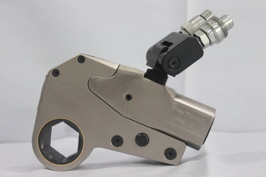
Hydraulic torque wrenches have revolutionized various industries by offering precise and powerful solutions for tightening and loosening bolts and nuts. These versatile tools are essential in many applications, making them a sought-after choice for professionals across the globe. In this comprehensive guide, we will address all your questions and provide a thorough understanding of hydraulic torque wrenches, including their uses, application methods, specifications, and the best manufacturer to consider.
Understanding Hydraulic Torque Wrenches
Hydraulic torque wrenches are specialized tools designed to apply torque (rotational force) to fasteners, such as bolts and nuts, with precision. They use hydraulic power to deliver the required force, making them incredibly efficient and accurate. These wrenches are ideal for situations where precise torque values are essential, ensuring the integrity and safety of the assembly. Now, let's explore some of the key uses and applications of hydraulic torque wrenches.
Versatile Applications
Construction and Infrastructure Hydraulic torque wrenches find extensive use in construction and infrastructure projects. They are perfect for fastening large bolts in steel structures, bridges, and buildings, where precision and reliability are paramount.
Oil and Gas Industry
In the oil and gas sector, these tools are employed for maintaining pipelines, drilling operations, and equipment assembly. Hydraulic torque wrenches offer the necessary torque accuracy, reducing the risk of leaks and ensuring safe operations.
Manufacturing Industry
Manufacturing industries often rely on hydraulic torque wrenches for assembling heavy machinery, engines, and automotive components. These tools guarantee consistent bolt tightening to meet industry standards.
Aerospace Industry
In the aerospace industry, where precision is critical, hydraulic torque wrenches are used to secure aircraft components. They ensure that fasteners are tightened to exact specifications, contributing to flight safety.
Using Hydraulic Torque Wrenches
The operation of hydraulic torque wrenches is straightforward. They typically consist of a hydraulic pump and a wrench head. Here's how they work:
Connect the wrench head to the fastener to be tightened or loosened.
Attach the hydraulic pump to the wrench head.
Pump the hydraulic fluid into the wrench, applying torque to the fastener.
Once the desired torque is achieved, release the hydraulic pressure, and the wrench will stop applying force.
The result is a precisely tightened or loosened fastener, reducing the risk of over-tightening or under-tightening, which can lead to mechanical failures.
Specifications to Consider
When choosing a hydraulic torque wrench, several specifications are important:
Torque Range: Ensure the wrench can provide the required torque range for your specific application.
Accuracy: Look for a tool with a high degree of accuracy to meet industry standards.
Size and Weight: Consider the size and weight of the wrench, especially if you need to work in tight spaces.
Durability: Opt for a durable, high-quality wrench that can withstand the demands of your industry.
Tritorc: Your Trusted Manufacturer
When it comes to hydraulic torque wrenches, Tritorc stands out as one of the best manufacturers in the industry. Known for Our precision engineering, Tritorc's products are synonymous with quality and reliability. Our extensive range of wrenches caters to a wide variety of applications and torque requirements. By choosing Tritorc, you can trust that you're investing in a tool that meets and exceeds your expectations.
0 notes
Text
Process & pipeline services
These services are crucial in ensuring the reliability, safety, and efficiency of pipelines in various industries, including oil and gas, petrochemicals, and utilities. They help prevent leaks, assess pipeline integrity, and ensure compliance with regulatory standards. Process & pipeline services
0 notes
Text
Difference Between Regular Sockets and Impact Sockets
Implements used to tighten or loosen fasteners have changed over time, but as the production of steel became more reliable and consistent grade/quality of steel became possible, fastener manufacturing became rapidly standardized along with a litany of tools and implements to fasten them.
Ring Spanner Wrench
Torque wrenches also started having ratcheting mechanisms, which brought forth the advantages of the sockets.
Let us understand what a socket is:
The amount of torque applied and the socket selected is decided by several factors:
Diameter of Bolt and Nut A/F (Across Flat) size
Torque applied
Geometry of the socket as per space restrictions
Material of the socket
Steps to select sockets for torqueing and detorqueing:
The diameter of the bolt and the Nut A/F (Across Flat) size.
Once this is understood, depending on the environmental factors, the lubrication around the bolt, one can calculate the torque required.
Selection of the right torque wrench is the next step.
Once the square drive size of the wrench is known, one can select the appropriate material for the socket that shall be used.
The socket can now be selected according to the square drive size and the Nut A/F (Across Flat) Size.
Difference between Regular Sockets and Impact Sockets:
Regular Sockets and their wrenches are made for use with manual and select electric torque wrenches, which provide light torque capacity for applications such as automotive applications, and everyday uses.
Whereas, Impact sockets are meant for industrial applications wherein the torque value is much higher and the use of power tools such as impact wrenches, hydraulic torque wrenches, pneumatic torque wrenches, electrical torque wrenches along manual torque wrenches and torque multipliers is a given.
Then, What makes impact sockets well-suited for industrial applications:
There are several factors that make them better, viz.
Better Material Selection: The materials used for impact sockets usually are made from Chrome Molybdenum Steel Alloy grades such as EN19, EN 24 & EN 47. A known characteristic of this steel allows the socket to sustain shocks and impacts from impact sockets and have a long durability in the face of repeated use.
Heat Treatment: The Steel billet, post machining must undergo heat treatment such as annealing to relieve stresses caused by the processes and add to the resistance against shocks and torsional forces.
Anti Rust protection: The sockets undergo black zinc plating, this layer is sufficiently applied to allow resistance against rust and other abrasion.
Precise Machining and Geometry: Apart from adhering to standard dimensions for impact sockets, shapes introduced such as rounded edges to openings allow the torsional forces to be applied to the flanks of the sockets instead of the corners this disallows crack formation at the edges.
What type of Impact sockets exist:
Impact sockets can be classified into several types such as the following:
Square Drive Size: The square drive sizes of wrenches are usually divided to imperial sizes in inches most common ones being — ⅜”, ¼”, 7/16”, ½”, 9/16”, ⅝”, ¾”, 13/16”, 1”, 1–½”, 2–½”, 3–½” and #5 Spline Drive. As we know an inch is divided into 16 parts of which these sizes are usually present.
Opening Type: According to the Nut location and space restrictions, use of Allen head bolts, we can select from
6 Points Hexagon
InHex Male Hexagon Driver
Male Square
12-Point Double Hexagon Sockets
4 Point Square Socket and many more….
Types of Sockets Opening
Sr.No.
Type of Socket Opening
Symbol
6 Points Hexagon
Nut Size: The Nut size changes according to the Bolt and whether it is a heavy hex nut or a finished nut, Sockets can be selected accordingly
Materials and Socket Geometry: According to the Square drive to opening ratio 4 different predominant geometry types for impact sockets exist. Additionally, the impact socket materials can be selected according to the amount of torque and
Variant according to function: Various functions call for different types of sockets such as the following:
Magnetic
Extenders
Torsion Bars
Thin Wall Long
Long and standard length
Loss of Vibration
Adapters (Male to Male / Female to Female)
Insert Adapters
Universal Sockets
Conclusion:
Industrial Heavy Impact sockets find use with proven power tools such as Hydraulic Torque Wrenches, Pneumatic Torque wrenches, pneumatic impact wrenches, electric torque wrenches, battery torque wrenches, manual torque wrenches, and Torque Multipliers.
Applications include ones in Oil & Gas Sector, Wind Energy Sector, Thermal Power Sector, Nuclear power sector, Mining, Automotive sector, etc. Customized Sockets to fit into specific applications can also be made as per requirements.
0 notes
Text
The Ultimate Guide for Hot Tapping
In the world of industrial piping, hot tapping is a cutting-edge technique that has revolutionized the way connections are made without interrupting the flow of fluid or shutting down operations. Often compared to the analog of bypass surgery, hot tapping offers a minimally invasive solution to access existing pipelines and equipment, making it a necessity in many industries. In this article, we will explore the concept of hot tapping, its advantages over traditional methods like line stopping and line plugging, and the global standards that ensure safe and efficient implementation.
An Introduction to Hot Tapping and Its Necessity
Hot tapping, also known as pressure tapping or under-pressure drilling, is a specialized technique used to join pipelines and vessels without shutting them down. Just like how a skilled surgeon performs bypass surgery without stopping the heart, hot tapping allows engineers to make new branch connections to an operating system safely and efficiently. This is crucial when halting operations is not feasible or would lead to significant downtime and financial losses.
The Difference Between Hot Tapping, Line Stopping, and Line Plugging
Hot tapping stands out from line-stopping and line-plugging techniques due to its unique approach. In line stopping, a temporary plug is inserted to stop the flow of fluid, allowing modifications to be made safely. Line plugging involves sealing the line completely, and isolating the section where work is to be performed. Hot tapping, on the other hand, enables connections to be made while the system remains operational, reducing downtime and the associated costs.
The Advantages and Risks Involved in Hot Tapping and Line Stopping
Hot tapping offers several advantages over traditional methods. The most significant advantage is the ability to continue operations uninterrupted, minimizing production losses and ensuring business continuity. Additionally, hot tapping is a more cost-effective solution as it eliminates the need for extensive shutdowns and subsequent restart procedures.
The Process of Hot Tapping and Coupon Retrieval and the Machinery Used
The hot tapping process involves several critical steps. First, a tapping machine is secured to the pipeline, creating a pressure-tight seal. Then, a hole is cut into the pipe, while maintaining the flow of fluid. Once the desired branch connection is established, a completion plug is inserted and sealed, ensuring no leaks occur.
Coupon retrieval is another vital aspect of hot tapping. During the process, a coupon (a small metal disc) is cut from the pipeline. This coupon must be retrieved to avoid potential damage to downstream equipment.
The Standards Followed Globally to Ensure Safe and Correct Hot Tapping
Hot tapping is a delicate operation that demands strict adherence to global safety standards. Organizations like Tritorc are committed to promoting safe and efficient hot-tapping practices. These industry leaders provide comprehensive guidelines and training to ensure that hot-tapping procedures are executed with utmost precision and safety.
Conclusion
Hot tapping has emerged as a game-changer in the industrial piping world, allowing for connections and modifications to be made without interrupting operations. Unlike traditional methods, hot tapping eliminates the need for shutdowns, minimizing downtime and costs. While it presents certain risks, following global safety standards and employing experienced professionals ensure safe and efficient implementation.

Hot tapping
0 notes
Text
The Pipe Cutting & Bevelling Machine That You Can Depend On
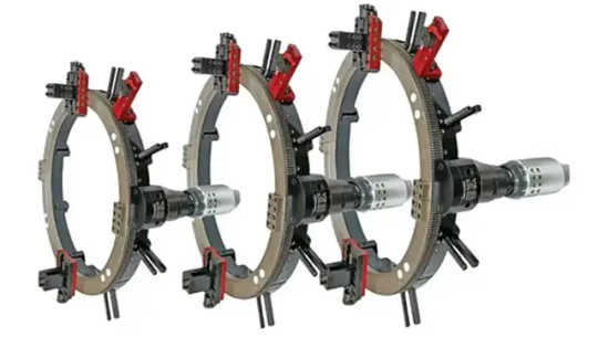
Pipe-cutting and bevelling machines have become indispensable tools in various industries, offering a multitude of benefits that streamline operations and enhance productivity. From critical applications in diverse sectors to their ability to cut weld material and work in constricted spaces, these machines have revolutionized the way professionals approach pipe fabrication. In this article, we will explore the exceptional advantages of having a pipe-cutting and bevelling machine, with a specific focus on Tritorc's innovative solutions.
I. Critical Applications in Various Industries
Pipe cutting and bevelling machines have extensive use in critical applications across various industries. From oil and gas to petrochemicals, power generation, and beyond, these machines are instrumental in projects involving pipeline installation, maintenance, and modification. In the oil and gas sector, for instance, these machines play a vital role in pipeline repair, ensuring efficient operations and minimizing downtime. Their application extends to the HVAC, construction, and shipbuilding industries, where precision cutting and bevelling are essential for optimal performance.
II. Machine Applications
From Steam Turbine Breech Nut Cutting to Weld Material Removal: One notable application of pipe cutting and bevelling machines is in the field of steam turbine maintenance, particularly in the cutting of steam turbine breech nuts. Tritorc's pipe-cutting machines have earned a reputation for their exceptional performance in this regard, providing accurate and efficient cuts to facilitate repairs and replacements.
Additionally, these machines are well-suited for cutting and removing weld material, allowing for the precise modification of pipelines and structural components. Their versatility makes them indispensable in a variety of projects, ensuring high-quality results and efficient workflow.
III. References to Tritorc and Its Machines
Tritorc, a leading manufacturer of pipe-cutting and bevelling machines in India, has been at the forefront of innovation in this field. Their dedication to providing cutting-edge solutions has earned them a reputable status in the business. Tritorc's machines offer unparalleled precision, durability, and versatility, catering to the diverse needs of professionals across different sectors.
IV. Operating in Constricted Spaces
Overcoming Limitations: One of the significant advantages of pipe-cutting and bevelling machines is their ability to operate effectively in constricted spaces. Traditional cutting methods often struggle with limited accessibility, hindering project execution. However, Tritorc's machines are specifically designed to address these challenges, providing compact and portable solutions that excel in tight spaces. This enables professionals to carry out precise cutting and bevelling operations with ease, even in the most challenging environments.
V. The Leading Pipe Beveling Machine Manufacturers in India
In India, Tritorc stands out as one of the leading manufacturers of pipe beveling machines. With their commitment to quality, innovation, and customer satisfaction, Tritorc has gained the trust of industry professionals. Their comprehensive range of pipe beveling machines caters to various pipe diameters and beveling requirements, ensuring that customers can find the ideal solution for their specific applications.
Conclusion
The advent of pipe-cutting and bevelling machines has transformed the industrial landscape, enabling professionals to streamline operations, improve efficiency, and achieve superior results. Tritorc, as a renowned manufacturer of these machines in India, has played a pivotal role in driving innovation in the field. With their exceptional performance in critical applications, ability to cut weld material, and adaptability in constricted spaces, Tritorc's machines have become essential assets for professionals across industries. By embracing these cutting-edge solutions, companies can elevate their pipe fabrication processes, minimize downtime, and enhance overall productivity, leading to long-term success in their respective sectors.
0 notes
Text
A Brief Introduction to Hot Tapping & Line Stoppling
Pipelines are a conveyance medium for various fluids that are necessary to keep civilization functional. To keep these critical pieces of infrastructure functional, several tools, accessories and machinery are needed to keep up with the requirements of their maintenance, repair and overhaul cycles.
Productivity is critical for maintaining profitability for the large economies of scale plants that, to provide an example: refine crude oil into various petrochemical products. Various pipeline fluid mediums such as steam, flare gas, crude oil, water, etc. require careful handling while the pipelines carrying them are drilled into and the flow is redirected to a conduit and then to its original destination.
A main pipeline called a ‘mother pipeline’ is the one which has the flowing fluid. The pipes, which the mother pipeline could be connected to are called ’branch pipelines’.
Purpose of Conducting Hot Tapping would be amongst the following:
To remove a damaged or rusted section of pipes
2. To create a conduit for the fluid to another pipeline or avoiding a certain area and reconnecting to the same pipeline.
The Hot tapping machine shown below has the following components:
a) Full Encirclement Fitting or Joints — usually have a pipe flange attached to them.
b) Valve housing — Connected by bolts on the flange
c) Tapping Machine — This is the actual element which shall perform the cutting, it has a drive component or motor that is electrically or hydraulically driven and rotates the Boring Bar that moves back and forth using a hydraulic mechanism. Here the feed and speed can be controlled.
Welded Fittings Different Sizes of Split Tee Fittings
The process involves the following steps:
e) Welding or Bolting the appropriate Joints on the Pipes to be Hot Tapped in minimum number to carry out to the line stopping after hot tapping is conducted.
Split Tee Joint being welded Welded Tees on the Pipes where hot tapping and stoppling is to be
carried out and the new conduit is to be connected
Valve Housing being mounted on the relevant Split Tee Joint Smaller Tap with its own valve housing
Cutter with a Pilot Drill is used to remove the Coupon from A Manual Hot Tapping Machine is used to Drill a tap in front of the
the Pipe and it is secured behind the valve gate. actual hot tapping position, this shall be later used for pressure relief
Now that both the taps are opened the pipe sections to be connected, the conduit is inserted and bolted on the valve housings of both, hence continuing the flow of the working fluid.
The Conduit Piping Connects the mother pipeline and ensures that the flow does not stop
Further, the Line Stoppling Machine is attached to the valve housing and the Stopple is extended into the pipe and the flow is obstructed. In Some cases an inflatable bag is used to stop the effervescent fumes from escaping to prevent an explosive environment or asphyxiating gasses from harming workmen or stopping their work. The excess pressure is released from the pipe which is now effectively cordoned off using line stopples.
The Line Stopple is inserted on both sides of the pipe section to isolated and the fluid in between is evacuated
The Damaged or rusted section of the pipe or the desired pipeline modification is initiated.
The evacuated pipeline allows for safe working with the isolated section and new pipe section can thus be added without loss of productivity.
The Line Stopple is now Withdrawn behind the valve gate and the excess gas (if any) is released. The fluid is now free to move through the pipe and hot tapping/line stoppling machines are now withdrawn.
Line Stopple Being Withdrawn Hot Tapping Machine being withdrawn Conduit Pipe Being Withdrawn
The Completion Flanges or blanks are now bolted and the welded fittings/joints are left in place, if the joints are bolted then they are withdrawn.
Completion Flanges are placed ensuring leakages at high pressure are unlikely
Standard Taps Offset Taps Lateral Taps
Special Underwater Sealed Valve Gates and Fittings and Joints ensure leak free hot tapping/ line stoppling material
0 notes
Text
The World of Pipeline In Situ Machining & Modification:
Beginning with channeling water for agricultural purposes, man has come a long way to the modern established standards of today that guide the manufacturing and safety standards of pipelines. Bringing Amenities such as Water & Gas to cities to interconnecting industries for supply of raw materials such as Petroleum and Petrochemical Products over large distances connecting raw material extraction points, processing points and ports of dispatch, Pipelines are ubiquitous and have a large variety of indispensable functions in modern civilization.


Pipes and Directional change connectors were used throughout the world (Left South Asia /Right southern Europe)
Pipelines allow steam to reach turbines and generate power, they convey bulk chemicals to be moved in medical tablets and supplement manufacturing plants. Pipelines are made from various materials. They were historically made from baked clay, chiseled stone, wood, etc. Modern Pipes are made from fiberglass, glass, steel, aluminum, plastic, copper, and concrete.

Process Equipment of a Pharmaceutical Plant

Steam Pipes in Turbine Rooms
Pipes in major industrial applications are primarily made of Metals with some Exotic Materials such as Inconel, titanium, chrome-moly and various other steel alloys. Pipes use in-line components, known as fittings,valves, and other devices, typically sense and control the pressure, flow rate and temperature of the transmitted fluid.


Inconel and Titanium Piping
Pipelines in the various sectors that use process equipment require timely maintenance, repair, refurbishment, and even the necessary modification; that companies might require to increase plant productivity in complex exercises that are a masterpiece conglomeration of fluid dynamics, design engineering, logistics, personnel management and use of innovative equipment.

These exercises are called shutdowns, and they require immense planning, and engineers keep them well defined with a limited scope. The reason for keeping their duration limited is to reduce the losses in productivity caused by a drop in product output of the plant. While reducing shutdown time, experienced crews and reliable machines must carry out the needed process with safety in mind considering potentially explosive environments.
Some Machining Techniques involve redirecting pipeline working fluid without stopping the flow of the fluid in a live pipeline as well, thus keeping productivity largely intact.
There are several methods of making these pipes and many more of cutting, welding, bolting, bending & connecting them. We shall focus on the methods involving In Situ Machining using highly mobile and flexible cutting techniques and the machinery that makes the same possible along with other processes that allow for pipeline modification and repair without bringing the pipeline or its section to any plant or machining site specifically.

Stationary Machining Station for Pipes inside a Plant

An Insitu Flange Facing Machine
Types of In Situ Machining Methods:
Pipeline Hot Tapping and Line Stoppling
Pipeline Water Jet Cutting
Pipe Cutting & Bevelling
Pipe Flange Facing
Pipeline Hot Tapping & Line Stoppling: Productivity is critical for maintaining profitability for the large economies of scale plants that, to provide an example: refine crude oil into various petrochemical products. Various pipeline fluid mediums such as steam, flare gas, crude oil, water, etc. require careful handling while the pipelines carrying them are drilled into and the flow is redirected to a conduit and then to its original destination.
A main pipeline called a ‘mother pipeline’ is the one which has the flowing fluid. The pipes, which the mother pipeline could be connected to are called ’branch pipelines’.
Purpose of Conducting Hot Tapping would be amongst the following:
To remove a damaged or rusted section of pipes
To create a conduit for the fluid to another pipeline or avoiding a certain area and reconnecting to the same pipeline.
The Hot tapping machine shown below has the following components:
i) Full Encirclement Fitting or Joints - usually have a pipe flange attached to them.
ii) Valve housing - Connected by bolts on the flange
iii) Tapping Machine - This is the actual element which shall perform the cutting, it has a drive component or motor that is electrically or hydraulically driven and rotates the Boring Bar that moves back and forth using a hydraulic mechanism. Here the feed and speed can be controlled.
iv) Cutter - The Cutting Element has a Pilot Drill which cuts and retrieves a cut section of the pipe called a coupon with a set of prongs that stop the cut section from falling back into the pipe.

Pilot Drill With Cutter

Hot Tapping Machine Diagram

Hot Tapping machine mounted on Pipe

Welded Fittings

Different Sizes of Split Tee Fittings
The process involves the following steps:
Welding or Bolting the appropriate Joints on the Pipes to be Hot Tapped in minimum number to carry out to the line stopping after hot tapping is conducted.
Examples include: Bolted or Welded Split Tee, Weld-O-Let, and Reinforcement (RF) pads

Split Tee Joint being welded

Welded Tees on the Pipes where hot tapping and stoppling is to be carried out and the new conduit is to be connected
Bolting of the Valve housing onto the joint is carried out which shall allow the tapping machine to be mounted on the same with smaller valves being fastened on the joints and correct measurements are made for the fittings.


Valve Housing being mounted on the relevant Split Tee Joint

Smaller Tap with its own valve housing
The Tapping Machine is mounted on the valve housing and the tapping is initiated using manual machines for the smaller taps and larger machines for the main taps

Cutter with a Pilot Drill is used to remove the Coupon from the Pipe and it is secured behind the valve gate.

A Manual Hot Tapping Machine is used to Drill a tap in front of the actual hot tapping position, this shall be later used for pressure relief
Now that both the taps are opened the pipe sections to be connected, the conduit is inserted and bolted on the valve housings of both, hence continuing the flow of the working fluid.

The Conduit Piping Connects the mother pipeline and ensures that the flow does not stop
Further, the Line Stoppling Machine is attached to the valve housing and the Stopple is extended into the pipe and the flow is obstructed. In Some cases an inflatable bag is used to stop the effervescent fumes from escaping to prevent an explosive environment or asphyxiating gasses from harming workmen or stopping their work. The excess pressure is released from the pipe which is now effectively cordoned off using line stopples.


The Line Stopple is inserted on both sides of the pipe section to isolated and the fluid in between is evacuated
The Damaged or rusted section of the pipe or the desired pipeline modification is initiated.

The evacuated pipeline allows for safe working with the isolated section and new pipe section can thus be added without loss of productivity.
The Line Stopple is now Withdrawn behind the valve gate and the excess gas (if any) is released. The fluid is now free to move through the pipe and hot tapping/line stoppling machines are now withdrawn.

Line Stopple Being Withdrawn

Hot Tapping Machine being withdrawn

Conduit Pipe Being Withdrawn
The Completion Flanges or blanks are now bolted and the welded fittings/joints are left in place, if the joints are bolted then they are withdrawn.

Completion Flanges are placed ensuring leakages at high pressure are unlikely
Various Orientations wherein the Hot Tapping and Line Stoppling Process could be carried out include the following:
Special Underwater Sealed Valve Gates and Fittings and Joints ensure leak free hot tapping/ line stoppling material
B) Pipeline Water Jet Cutting:
In Explosive Environments the use of conventional pipe cutting techniques and machines is hazardous. To carry out In Situ Maintenance, Repair and Overhaul of pipes thus calls for a truly spark free operation. Water concentrated with high pressures has been used for cutting wood since the late 20th Century. Since then the process has evolved to also include metals of large thickness.
Water is pressurized using specialised pumps and the water is mixed with powdered garnet or other abrasives. This abrasive mixed slurry is released out of a narrow nozzle measuring 0.1 mm to 0.5 mm with very high pressure measuring at 1000s of Bars of Pressure. The Accuracy of this process in some cases even surpasses Laser Jet Cutting due to lack of heat distortion.
20 mm mild steel, cut with the Hydro Jet (left) and laser jet (right)
Pipeline Being Cut using Guide Rail and Water Jet cutting method
Thus to elaborate, this process has the following machinery & equipment involved.
Water Tank and Pump
Intensifier Pump
Pneumatic Abrasive Delivery Feeder
Magnet Abrasive Tank
Magnetic carriage for the Waterjet Nozzle and Regulator
Remote Operation Pendant
High Pressure Pipe to connect intensifier pump and tools
The Use of High pressure Pumps and pneumatically pressurized abrasive material to mix it with water. The Slurry is then jetted out of a fine nozzle to cause material removal on the workpiece.
C) Pipe Cutting and Bevelling Machines:
A Quick, Reliable & Relatively Cost Effective method of Pipe Cutting is a frequent need in Oil and Gas Plant and the connecting Pipelines from Oil Wells to Distributors and everything in between. The ability to machine, isolate and prepare pipes for welding without moving them to a different location entirely is highly desirable.
A portable & lightweight machine which is sturdy is industry standard. The Insitu machining would be incomplete without these machines.
These machines are mounted on the Internal Diameter or the External Diameter of the Pipe and the locator pads are fastened against the pipe according to its ovality. A point to keep in mind is that the seamless or seamed pipes are never fully uniform in thickness or in their roundness.
Pipe Ovality Measurement- (MaxOD – MinOD) / NomOD *100 An Exaggerated Diagram showing the Ovality of a Welded Pipe
Cutting pipes with Conventional Pipe Cutting Methods is hazardous in explosive environments, thus being able to utilize safer drive methods such as pneumatic pressure is preferable.
An Air Operated Motor That Drives the Rotating Ring on the Pipe Cutting Machine. It is mounted on the gearbox assembly on the machine.
Hydraulic Powered Motor Electrical Motor operated Pipe Cutting Bevelling Machines
Risk Assessment and Hazard Mitigation:
Machine Tools are specifically designed to perform precise material removal operations.
Stationary Machine Tools include lathes and milling machines and are typically found in a machine shop. They are mounted in fixed locations during operation and are considered to be a complete, self contained machine. Stationary Machine Tools achieve the rigidity needed to accomplish material removal operations from the structure that is an integral part of the machine tool.
In contrast, Portable Machine Tools are designed for on site machining applications. They typically attach directly to the workpiece itself, or to an adjacent structure, and achieve their rigidity from the structure to which it is attached to become one complete machine during the material removal process.
To achieve the intended results and to promote safety, the operator must understand and follow the design intent, setup, and operation practices that are unique to portable machine tools.
The operator must perform an overall review and on site risk assessment of the intended application, Due to the unique nature of the portable machining applications, identifying one or more hazards that must be addressed is typical.
A Standard understanding of joining two pipes using welding
To Elaborate further on how these machines work:
Here, we shall assess a portable pipe cutting machine/lathe that can sever and bevel pipelines simultaneously in pipeline. These machines can form any bevel angle as they cut. These tools are portable machines that are strong enough to cut and bevel heavy wall pipes and rigid enough to reface worn flanges. The frame is split for easy installation and the tools bits automatically feed into the workpiece with each rotation of the lathe to assure precision machining.
Machining Function & Ability:
Sever In line Pipe
Sever and Bevel In Line Pipe
Sever and Double Bevel In Line Pipe
Socket Weld Removal
Housing
Rotating Rack Ring Assembly
GearBox Drive Assembly
Bearings
Tools Post Slide Assembly
Tripper Assembly
Universal Locator Assembly
Diagram showing designated components
Housing: An Aluminium Split Ring Housing, Connected with Swing Bolts, that is capable of being dismantled for installation on in line piping. The housing has bearing mountings for the rotating cutting head, a mount for the drive motor for drive motor assembly, and locator pockets.
Rotating Rack Ring Assembly: Made of Alloy Steel, this split ring assembly, connected by the gear clamps, will align with the split lines of the housing when the machine is split into halves. The Cutting head assembly has gear teeth on the outside diameter of the cutting head and mounting locations for the slide assemblies. An internal bearing race allows the cutting head to rotate about the housing.
GearBox Drive Assembly: Mounted to the housing and arranged with a pinion gear on a shaft. The motor mounting bracket is designed to accept the reaction torque generated by the drive motor. Alignment keys are used to guarantee perpendicularity between the motor and the cutting head.
Bearings: The Cutting head assembly runs on bearings that provide for axial and radial force reaction. The bearings are adjustable to compensate for normal wear.
Tool Post Slide Assembly: The Slide Assembly is designed to hold the cutting tool (tool bit). The slide assembly has adjustable jibs and also contains a feed screw assembly, which is used to feed the tool bit into the workpiece. The slide assemblies are bolted to the face of the machine assembly and can be moved in increments.
Tripper Assembly: The Tripper assembly is designed to hold the tripper pin. The Tripper pin used to turn the star wheel on the feed screw assembly, which feeds the tool bit into the workpiece. The tripper assembly is bolted to the OD of the housing. There are four different types of mounting locations that allow for more flexibility in the machine mounting.
Universal Locator Assembly: The alloy steel machine uses adjustable locator assemblies with some travel range. Turning sort screws located on the outside of the housing actuated the adjustable locators. Locator extensions are required to mount on a smaller diameter pipe. Not Applicable in case of universal locator assembly.
For a better understanding watch the below video by clicking on the link:
Tritorc - OD Mounted Pipe Cutting Beveling
Let us now understand the steps to operate these machines in detail:
Prep work:
Clear all the obstructions and non essential personnel and equipment
Check that the area where the control/observation area of the machine is not located in the path of the hot flying metal chips
Mount the machine securely to the workpiece.
Make sure that the pneumatic/ air hoses are routed and secured in a manner that ensures that no trips over them, they do not entangle with other equipment, in the path of the hot metal chips. ensure clearance to make sure damage to other equipment is minimal in case the air hose fails.
Check the tools for their condition and sharpness
Ensure all hand tools and loose parts and equipment are removed from the area of operations.
Installation of the machine:
Motor Mounting
Machine Operation:
Now that the machine and the tool bit have been properly secured on the pipe. The cutting operation can be initiated.
The Cutting Operation is continuous operation until stopped by the operator to stop the cutting feed during rotation, lift the tripper handle and let the machine rotate a few times to clear the tool bit. Turn off the power to stop the machine rotation. Letting the tool bit clear will prevent tool damage and gouging.
Engage the tripper pin by pushing down on the tripper handle. If Chatter or vibrations occur, reduce cutting RPM. If the tool bits chip or become dull, replace them immediately with sharp bits. Do not sharpen the tool bits. They must be sent to the factory for regrinding to maintain proper relief angles. Damage to the machine could occur. Use coolant during the cutting operation to reduce friction on the cutting edge.
Stop the machine when the severing is complete. Back put the tool blocks with the star wheel wrench to the full position.
Follow tool bit setup procedures replacing both sever bits either left hand or right hand sever, bevel combinations. Back the bevel nit above the server bit and follow the procedure above, until the pipe is severed and bevelled.
Machine Removal:
Retract Tool Slide
Disconnect power source and remove motor
Loosen the expanding blocks that hold the split frame in position.
Remove the split frame from the pipe.
D) Pipe Flange Facing: Apart from Sockets and Spigot Joints which are very common in concrete pipes, large metal pipes use flanges to provide an easier customisation & maintenance access and also suitability for a wide range of volume, temperatures and pressures of various chemicals whether they are gasses or liquids.
A Flange is an effective and proven mechanical member of a piping system. Its primary function is to allow access for inspection, cleaning, maintenance, repair, and even modification of the system. These are either welded or screwed into the primary piping system. Operators fasten Flanged joints by bolting together two flanges with a gasket to provide a seal. Flanges allow us to install components in the piping system.
Several Flange types are used primarily in the Petrochemical and Chemical Industry some of them are:- Welding neck flange, Slip-on flange, Socket Weld Flange, Lap joint flange, Threaded Flange, and Blinded Flange. Manufacturers make these flanges using stainless steel, cast iron, aluminium, brass, bronze, plastic, etc., but the most used material is forged carbon steel and has machined surfaces.
The interfaces between these flanges connecting two pipes are called flange faces. A flange face is its sealing face.
Here are shown below bolted joints on the blade of the flange and the flange facing required to make sure that the gaskets used to connect and ensure leak free joints have a proper seat on them.
Types of Misalignment that can happen due to several factors, like improper bolting, misalignment in pipeline foundations, temperature, pipe fluid pressure, gasket selection, improper welding, etc.
Types of gaskets ranging from Metallic Gaskets, Spiral Wound Gaskets, PTFE (Teflon) Sheet & Molded Gaskets, Compressed Non Asbestos Fiber Sheet, Premium Grade Rubber Sheet.
We shall now focus on the flange mating interfaces and the types of surface finish.
Flange surface faces can be classified as smooth (also called ‘flat’ or ‘plain’) or serrated. Smooth faces appear visually ‘smooth’ and have no visual tool markings. Serrated faces have some form of tool markings on the flange face.
Flange Face Surfaces An Example of Serrated Surface finish
Flange assembly must be mated and tightened to the required torque in order to seal correctly.
High-temperature and high-pressure system flanges use a serrated sealing surface, or a metal gasket. Low-temperature and low-pressure system flanges may use a smooth flange face surface and soft gaskets.
Smooth Flanges:
Smooth Flange surfaces have a finish that is featureless and have a smooth flange surface on the entire flange face. Seal integrity is determined by many factors, including -but not limited to:-
Gasket sealing material.
Gasket design.
Flange construction material.
Service conditions (temperature, pressure etc.).
Following the correct bolting procedure.
Serrated Flange Surface:
Serrated flange surfaces consist of concentric circular grooves, or a continuous spiral groove (also known as ‘phonographic’) machined onto the flange sealing surface. Serrated flange surfaces use non-metallic (soft) and semi-metallic gaskets.
The image below shows the two serration types. The spiral serration in the image is exaggerated because it is sometimes difficult to see the spiral shape on a real flange, due to the closeness of the serrations.
Concentric (left) and Spiral (right) Serrations
Serrations provide more resistance when mating with gaskets, which ultimately leads to a lower probability of leakage as the likelihood of gasket dislocation (un-sealing) is reduced; this is true even when less sealing pressure (bolt torqueing) is applied.
Now to focus on the machines that makes these machining patterns:
There are predominantly two types of these machines which can be distinguished by the mounting type:
Internal Diameter Mounted
Outer Diameter Mounted
These machines depending on the space available and the restrictions around the pipe are selected. The Machines can perform the tasks such as the following:
Flange Facing and Bevelling
Machine Seal Grooves
Make Serrated Finishes (Phonographic)
Continuous Groove Facing Feeds
The machines must be necessarily portable to be transported to the site for the machining to begin and must be sturdy to face the flange accurately.
An Internal Diameter Mounted Flange Facing Machine facing a raised face flange (left) & an Outer Diameter Mounted Flange Facing Machine (right)
We will now understand how these machines work:
The Flange flange machine is a three piece mounting system that makes setup and alignment of this machine quick and easy. It is lightweight, portable. This machine allows you to face, bevel, turn pipe, valve and pump flanges with ease.
The flange facing machine should be aligned with the internal diameter correctly with the necessary steps and the cutting tool is adjusted according to the cut desired.
The end result is that the gasket is mounted without slipping from the flange face.
A few safety instructions before operations can begin:
Safety Protective Equipment must be worn at all times during machine operation and the clamping machine must be locked properly. Adjust the workpiece at low speed but not at high speed. Stay away from rotating equipment to prevent injury. Electrical wires should be kept far away from high temperature, oily or sharp places.
When there is malfunction or abnormal sound, the power supply shall be shut down immediately through remote control and then to start checking and repairing. Do not let the machine operate without anyone watching. Operators can only leave after the machine stops and make sure the power supply is switched off and transmission system is in free position. Do not run the machine beyond its capacity.
Oil stain and iron dust shall be removed after work is done. And anti-corrosive oil shall be put on the cutting arm and main axis.
Conclusion:
The practice of In Situ Machining is an important fixture in the world of Pipeline Maintenance, Overhaul and Repair. The tools and machines mentioned here are indispensable to this task. Machining pipes to prepare them for welding and customizing pipelines to add capacity to plants in the same location where they are supposed to be installed is a boon that reduces downtime and increases plant productivity. This in return makes our lives better as the amenities continue to flow when pipes are joined for sure.
1 note
·
View note
Text
An Introduction to Bolting
An Introduction to Bolting
Since antiquity, Humans have used fasteners to hold components and objects together. They have evolved according to need and time. The modern bolt is a highly standardized and widely accepted engineering implement. These bolts must sustain several stresses and strains as mechanical members & as a part of structures and machines. They offer excellent advantages, such as a reliable temporary joint with some prudent flexibility that allows it to sustain shocks.
Archimedes Screw Archaeological digs regularly regurgitate metal nails and rivets
The Modern fastener is a merger of ideas
A Cylindrical rod with helical grooves or threading and hexagonal stoppers with internal helical grooves or threading to hold two objects while passing through a hole; is a mere simple description of the modern engineering marvel that is the mechanical bolt or stud. To specify, A stud has no fixed end but a bolt has a fixed end. Fasteners in general surround us in our lives.
Bolts must be fastened on the various surfaces and available spaces with the appropriate amount of torque or tension, depending on the application. A reliable tool can allow the operator to use little effort and time and remain safe while completing the task. There sre multiple type of fasteners. But, we shall learn about all these topics going forward related to bolts in particular.
Bolts and Studs are foundation of modern industries
Categorization of Bolted Joints:
Bolted joints could be classified into three major categories according to application. For convenience, broad classifications are made under these umbrella terms.
Process Equipment and Piping related joints: It is a joint generally consisting of a gasket or seal, and covering or connecting two or more vessels or pipes with Flanges that are bolted together would be classified under this section. These joints require occasional removal and retightening for purposes of maintenance, overhaul, or repair of the said pipe or process equipment. Eg.: Oil and Gas Production Industry.
2. Machinery Joints: It is a joint that is made on static or dynamic components of machinery or vehicles and generally has direct metal-to-metal contact. This type of joint requires frequent opening and closing due to inspection, maintenance requirements. Eg.: Powerlant Machinery.
3. Structural Joints: Meant for all types of bolted structures, buildings, and bridges. It is a joint that also has direct metal-to-metal contact but generally does not require opening and closing of the joints until there is an urgent requirement for refurbishing for safety purposes, relocation, overhaul, or demolition.
A Dynamic System:
Although a bolted joint might look static, it has several forces acting on it and it too exerts its own forces on the joints it holds together.
A bolt offers certain unique advantages such as the following:
A Bolt is removable and can be reused several times without using much of its original strength and properties.
A Bolt holds joints together under tension and exerts clamping force on the joint. This ensures that the bolt shall continually expand/stretch (like a tension spring) and the joint shall always contract (akin to a compression spring).
Bolts act like springs thus they can sustain forces/pressures trying to overcome the clamping force and hold the joint together.
To elaborate further,
The force that the bolts exert on the joint is called a ‘clamping force’. A clamping force is also called a preload. total preload must be greater than the pressure trying to push the joint apart.
Since a bolt is akin to a compression spring, it shall have the Hook’s Law apply to it as well. Which says that the Force and elongation/stretch are directly proportional within the elastic limit of the material.
Every material has a certain yield strength, beyond which the material shall cross its elastic limit and cannot retain its original shape. It shall have thus entered its plastic range and the deformation/elongation shall be permanent. Additionally, if the material crosses this Plastic range it shall suffer from necking and fracture/buckle under the load.
A bolted Joint is thus a Tension Spring within a Compression Spring. Thus we need enough spring action to Clamp the joint together but not too much so that the bolt yields and no longer springs back.
For Bolting purposes, we generally limit the usage of bolts within a ‘safe region’ of 30% to 70% of their yield strength, allowing some safety margin to compensate for environmental factors and material properties. This varies according to applications, to speak of examples
Pipeline Flange-based joints: 40 to 50 % of the Yield Strength - This limitation aims to ensure that the gaskets usually present in these joints are used optimally and are not crushed by the Pipe flanges.
Machinery Joints: 65 to 70 % of the Yield Strength - This limit is due to the frequency of the tightening and loosening of the bolts.
Structural Joints: 85 to 90 % of the Yield Strength - Here, the bolts are rarely unfastened thus they can be tightened to the maximum considering only a marginal safety factor.
To tighten bolts to the optimum value we must have a datum to refer to, thus the need for standardization. This has produced three commonly used and accepted standards for bolt manufacturing amongst many. Standard fasteners are specified by various organizations. These fasteners are typically specified according to their yield strength.
SAE - Society of Automotive Engineers (Section - J429)
ASTM - American Society of Testing Materials (Section - A193)
ISO - International Standard Organisation (Section - 898)
An ISO 10.9 Grade bolthas marking on the face of the bolt with a number that designates the maximum tensile strength and the approximate yield strength. While one can know about the SAE grade of the bolt accordig to the number of markings on the face of the bolt and add 2 to it.
This gives us a reference as to the applicable limits of the bolts.
There are two primary methods of stretching a bolt, viz.,
Torqueing
Tensioning:
Hydraulic
Mechanical
Induction Heating
Torquing method:
It can be defined as Turning the nut with friction
Threaded fasteners have screw threads in the form of an inclined plane. As the bolt turns in the nut it creates a mechanical advantage capable of high forces. Applying torque is the most common method of controlling the tightening process.
Torque is the force multiplied by the distance or length of the lever arm.
Torquing force can be calculated using the following formulae,
Torque = Force X Length
Eg.: Torque = 100 X 1 = 100 Ft.Lbs.
Metric units for torque will be measured in Newton Meters (Nm).
One may increase torque by increasing the lever arm length or increasing the applied force
Torque = K X D X F / 1000 = Nm or K X D X F /12 = Ft. Lbs.
D - Diameter of the Bolt
F - Force
K - Coefficient of Friction
For Torque Tools, there are several ways of classifying them. One method is according to the source of power:
Manual - Click, Dial, Electronic Manual Torque Wrenches
Electric
Pneumatic
Hydraulic
Classifying Bolting according to the degree of torque control leads to three classifications:
Uncontrolled Bolting - There is no measure nor control of the amount of Torque Being applied
Eg.: Spanner or Hammer
Partially Controlled Bolting - There is control of input but we cannot control or predict the exact output due to a lack of a feedback mechanism or information for the exact elongation in the bolt.
Eg.: Hydraulic Torque Wrenches, Pneumatic Torque Wrenches, Electric Torque Wrenches, etc.
Fully Controlled Bolting: There is a control of input and it is informed by the feedback from devices such as Ultrasonic bolt tension monitors
Eg.: Hydraulic Torque Wrenches , Pneumatic Torque Wrenches , Electric Torque Wrenches , etc. in combination with Ultrasonic bolt tension monitors.
It is certain that all torque tools depend on the same principle of Action & Reaction which can be more accurately defined by Newton’s Third Law of Linear Motion: Every Action has an Equal and Opposite Reaction.
By giving a basic derivation of this law we can say that,
Newton’s Third Law of Rotation: For Every Applied Torque, there is an equal and opposite reaction torque.
The application of torque by the driver generates an equal and opposite torque on the tool which must be braced with a reaction arm.
Using conventional torque tightening, extremely high reaction forces impact the equipment. These reaction forces can be extremely hazardous and even damage equipment.
Tools that do not distribute reaction forces into a reaction surface, usually end up transferring these forces into the hands of the user. Eg.: Impact Wrenches - cause Hand Arm Vibration Syndrome.
To elaborate on the earlier mentioned K factor in the torque formula,
Friction is the force resisting the motion of solid surfaces sliding against one another. Friction arises from surface imperfections as surfaces move against each other.
Friction is the main factor for the loss of most of the torque energy used to tighten a bolt. An estimated 90% of this torquing input energy is lost overcoming friction.
The usual locations and surfaces are usually situated under the head of the bolt, nut, and threads. Barely 10% of the input energy is converted to bolt stretch/elongation.
Because of this, lubrication of the bolt is necessary to ensure that the least amount of torque is required.
Generally, once the fasteners are lubricated nearly three times less torque is required. Although, one must ensure that the lubrication is applied to both the bolt threads and the nut face.
General description and modus operandi for Hydraulic torque wrenches:
Hydraulic Torque Wrenches are a ubiquitous workhorse of the bolting world. They can provide predictable torqueing for long operations. They come in various bolt sizes and can work irrespective of thread profiles. They have two major variants viz.: Low Profile or Ratchet type and Square Drive type . The modern hydraulic wrench uses features such as a swivelling hydraulic manifold, self ratcheting drives, narrow nose radii and light weight body amongst many other advantages.
Square Drive Hydraulic Torque Wrench Low Profile/Hex Drive/ Ratchet
Type Hydraulic Torque Wrench
Hydraulic Torque Wrenches - Square Drive Type Cross Section Hydraulic Torque Wrenches - Hex Drive Low Profile Type Cross Section
Hydraulic Torque Wrenches Front View Show the advantages of using the Low Profile Torque Wrench in constricted Spaces
360⁰ X 180⁰ freedom of movement for the Swivelling Hydraulic Ports.
This tool requires a Powerpack/ Hydraulic pump to push a cylinder to move a drive which rotates/torques the bolt. The square drive is mounted with a socket that fits over a bolt. Usually a back up wrench is used to brace the nut from behind for a successful torquing operation.
Detachable Reaction Arm, Sliding Square Drive, Laser Engraved Torque Chart allow easy reference and flexibility to reach reaction surfaces for both tightening and loosening operations.
Operation for Bolt Tightening and Loosening:
Attachment of the desired Socket to the Square Drive Connection of the Hydraulic Hoses to the Connection of the hoses to the pump unit
Swivel hydraulic hose connector
First the size of the bolt to be tightened is identified and the appropriate socket is chosen to fit on it according to the space available.
The high pressure hoses are attached to the Square Drive Hydraulic Torque Wrench and the Pump Unit.
The flange to be tightened has the bolt holes numbered according to ‘star pattern’ bolting to ensure uniform compression of the flange.
Use ‘Star pattern’ Bolting pattern Place the Reaction Arm on a stable
reaction surface according to the tightening
or loosening operation
Initiate torquing whilst keeping a back up wrench or slugging wrench to brace the nut of the stud or bolt from behind.
Since the reaction arm is removable and the square drive can slide to other end of the tool, the torque wrench can be used to initiate loosening of the bolt after a few adjustments.
A standard addition to one’s tool kit concisiting of torque wrenches and other bolting tools
Tensioning method:
It involves Pulling or tensioning the bolt and then turning the nut without friction.
Hydraulic Tensioning:
In this method, a hydraulic bolt tensioner tool is used on the bolt. It generally has the following basic components
Thread Puller (Marked Yellow): A special type of nut that engages the stud and stretches the stud.
Hydraulic Cylinder & Piston (Marked Blue): Cylinder Body & Piston that lifts puller when hydraulic pressure is applied.
Bridge & Socket (Marked Cyan): A Platform that allows access to tighten or loosen the nut while the cylinder is under pressure, retaining the bolt tension.
The steps to operate a bolt tensioner include the following:
Attach the Stud
Apply hydraulic pressure to the tensioner stretching the stud.
Tighten/turn the nut against the flange to hold the stretch.
Release pressure and remove the tool.
There are several types of Tensioners some of them are as follows:
Multi stage Tensioners: These tensioners have a smaller diameter and have multiple piston to make sure that the bolts can be tensioned simultaneously by the multiple pistons with greater force that would otherwise not be possible in a small space.
Sub Sea Tensioners: As critical infrastructure on seabed based structures increases the need to maintain these structures also gains priority. Thus these corrosion resistant Tensioners with a split clamp are used to quickly latch onto the bolts on flanges of pipes to speak of an example. There is limited time due to safety concerns for the scuba divers and the underwater Remotely operated vehicles are costly to operate on an hourly basis, thus speed of operation is top priority for these applications.
Spring Return Tensioners: An increasingly common feature in all hydraulic bolt tensioners, the use of spring return mechanism for the load cell piston ensures that the operator does not have to manually lower the piston or puller bar using a tommy bar. Thus he can move onto the next bolt quickly and this reduces setup time or down time.
2) Manual Tensioning:
Without the use of any hydraulic or pneumatic power source, manual tensioning depends on using devices such as the Jackbolt.
here the radially arranged bolts are tightened in a diametrically opposite fashion, which leads a puller cylinder to tension the bolts.
3) Induction Heating:
Here, We heat the bolt to a certain temperature through an induction heater. This expands and elongates the bolt and allows the rotation of the nut. We rotate the nut by using a slugging wrench/spanner. But it is necessary to allow the bolt to cool down and thus achieve clamp force.
A special section for pressurized joints:
Bolting has critical application for pressurized joints related to pipes and process equipment.
A Flange is an effective and proven mechanical member of a piping system. Its primary function is to allow access for inspection, cleaning, maintenance, repair, and even modification of the system. These are either welded or screwed into the primary piping system. Operators fasten Flanged joints by bolting together two flanges with a gasket to provide a seal.
Several Flange types are used primarily in the Petrochemical and Chemical Industry some of them are:- Welding neck flange, Slip-on flange, Socket Weld Flange, Lap joint flange, Threaded Flange, and Blinded Flange. Manufacturers make these flanges using stainless steel, cast iron, aluminium, brass, bronze, plastic, etc., but the most used material is forged carbon steel and has machined surfaces.
There are gaskets that are used to ensure a proper joint between two flanges. According to the application, the flange faces have variants that find utility, here are some types of flange face types.
Full Face Flanges: Used with softer gasket materials.
Raised Face Flanges: Designed to deliver higher gasket loads.
Ring Joint Flanges: Used in high temperature and pressure applications.
Flange Alignment:
Pipe alignment, especially for large diameter pipes is a multispectral challenge, of which bolting is one aspect. These defects cannot be corrected by bolting alone.
To generalise bolting relevant pipe misalignment types there are two:
Lateral Misalignment
Radial Misalignment
Gaskets:
To compensate for minor machining errors, gaskets are used. They are available in various sizes and forms according their application., to name a few.
Metallic Gaskets
Spiral Wound Gaskets
PTFE (Teflon) Sheet & Moulded Gaskets
Compressed Non Asbestos Fibre Sheet
Premium Grade Rubber Sheet.
To achieve a Gasket Seal depends on applying the right pressure.
Parallel Joint Closure:
In most bolted connections, what you do to one bolt affects the other, thus making them interdependent.
Interdependent bolts must be tightened in a sequence (pattern) and gradually (in steps/passes) - It would be similar to the method applied to tightening bolts on a car tyre.
Many bolts are arranged in circular patterns, thus making it necessary to use a star like pattern to tighten the bolts. The same pattern must be followed for multiple passes, usually four passes with an increasing amount of load.
Pass 1 - 20 % to 30 % - (cross pattern) align, close gaps, seat gaskets.
Pass 2 - 50 % to 60 % - (cross pattern) apply incremental load
Pass 3 - 100 % (cross pattern) achieve target load
Check Pass (Dog Pass) - (circular pattern) check pass, even out load.
Single tool Bolting plan:
Number of Bolts in a sequence
Apply the torque in steps
Check the results
“Plus 4” method:
Approved method in ASME PCC-1
Number the bolt at the 12:00 position as 1, 6:00 as 2, 3:00 as 3 and 9:00 as 4.
Start at bolt 1, go clockwise and add 4 to the number of the previous bolt, starting again when you reach the bolts you have already numbered.
This pattern will work for all circular bolting layouts.
Certain precautions that one must keep in mind while operating these tools:
Wear PPE (Personnel Protective Equipment)
Head Protection: Safety Helmet
Eye Protection: Safety Glasses
Hearing Protection: Earplugs
Protective Clothing: Boiler suit, Safety harness (if working on height)
Hand Protection: Gloves
Foot Protection: Safety Shoes
Avoid Pinch Points:
Caution with Reaction Forces
Avoid Reaction Arm Pinch Hazard
Avoid Backup Wrench Pinch Hazard
Avoid Line of Fire:
Hydraulic Tensioning involves high-pressure hydraulic fluid, up to 30,000 psi.
Take caution with hydraulic pumps and hoses.
Avoid the line of tensioner fire.
Disclaimer:
Tritorc does not wish to infringe upon any copyrights related to the products, services or images used in this article.
0 notes
Text
Hydraulic Torque Wrench
Square Drive type: Tritorc TSL series
Technical specifications:
Tritorc’s Square Drive Hydraulic Torque Wrenches Cover a wide torque range from 108 Nm to 69247 Nm (80 Ft Lbs to 51073 Ft-Lbs) with 10 different models
The tool has aluminium alloy body construction
Weight of tools range from 1.8 kgs to 65 kgs (3.9 Lbs to 143 Lbs)
Vacuum heat treated components
Sizes of square drives available for the Hydraulic Torque Wrenches range from 0.75 Inch to 2.50 Inch (19.05 mm to 63.5 mm)
It is easy to use the tool:
Visible features:
A removable sheet metal chart with laser engraved torque rating in Nm and Ft-Lbs.
The hydraulic hose line coupler features a swiveling arm with 3600 X 1800 freedom of movement even if the line is at full pressure
Engineers have designed the quick-connect couplers to be leak-resistant even under pressure.
The reaction arm is fitted on the splined shaft with a simple quick-release button allowing quick switch over while fastening and unfastening bolts.
There is a provision for a lifting handle to manually transport the tool and Eye Bolts are available for bigger tools.
The reaction boot is available in multiple colors and the hard-anodized tool body & reaction arm is scratch-proof.
Subtle features:
Quick push-through drive for ease of fastening and unfastening of bolts.
Finer ratchet and pawl for better engagement
The multi-tooth drive segment allows up to 320 of movement in the square drive for the complete movement of the piston.
The drive plate and connecting piston are connected by a rod that eases the piston movement. This rod can be removed during maintenance when the piston is fully retracted.
The piston rod is a hard chrome plated component, which makes sure that the rod seal does not wear out easily.
The cylinder bore within which the piston moves is cold worked with a super finished surface for suitability in continuous operations for an extended time.
An overall stronger and more durable tool:
The reaction arm due to its fitting on a splined shaft is rigid during its operation and is thus suitable for heavy load application. The standard spline design has a torque effective length for exact Pitch circle diameter engagement of the reaction arm.
The reaction arm “boot” is made of an alloy steel
The Endcap is designed to bear sufficient back pressure so that the piston operation is smooth and the forward force is applied properly.
The drive components are made of alloy steel and are heat treated in a controlled vacuum heat treatment process increasing their strength and durability.
The seals are designed to sustain high pressure and make this tool suitable for static and dynamic loading applications.
The body of the Hydraulic Torque Wrench tool is made of machined high strength aerospace aluminium thus allowing it to be strong and light.
A versatile tool:
A quick response system for torques ranging from 108 Nm to 69247 Nm.
Cross compatibility with all Tritorc Power packs
Several tool inserts like Square drive, Direct drive socket, Direct drive Allen socket, Hexagon socket, and Bi Hex Socket are available for a flexible use profile.
The splined shaft allows the fitting of an Extended reaction arm, Extended Reaction tube apart from the default reaction arm.
Trust gained from 32 years of Service to you
Up to 12 Months of warranty*
Free Technical Consultation and Demo
Reliable after-sales support
What are various drive types that come with the tool?
Answer: Several tool inserts like Square drive, Direct drive socket, Direct drive Allen socket, Hexagon socket, and Bi Hex Socket are available for a flexible use profile.
Is there any accessory apart from the reaction arm that is available with the tool?
Answer: The splined shaft allows the fitting of an Extended reaction arm, Extended Reaction tube apart from the default reaction arm. The reaction arm is fitted on the splined shaft with a simple quick-release button allowing quick switch over while fastening and unfastening bolts.
How does Tritorc ensure that the components manufactured have high strength for the application desired?
Answer: The drive components of the Hydraulic Torque Wrenches are made of alloy steel and are heat treated in a controlled vacuum heat treatment process thus increasing their strength and durability.
How does one lift the tool without having to hold the main body?
Answer: There is a provision for a lifting handle to manually transport the tool and eye bolts are available for bigger tools.
Is this available in different colors?
Answer: The reaction boot is available in multiple colors and the hard anodized body and reaction arm are scratch proof.
Technical Data
Units
TSL-07
TSL-1
TSL-3
TSL-5
TSL-8
TSL-10
TSL-20
TSL-25
TSL-35
TSL-50
Square Drive
Inch
3/4
3/4
1
1.1/2
1.1/2
1.1/2
2.1/2
2.1/2
2.1/2
2.1/2
Min. Torque
Nm
108
178
420
725
1050
1533
2600
3460
4860
6925
Max. Torque
Nm
1130
1779
4204
7249
10800
15330
26675
34750
48675
69247
Min. Torque
Ft. Lbs.
80
131
310
535
775
1131
1917
1551
3611
5107
Max. Torque
Ft. Lbs.
830
1312
3098
5347
7965
11307
19675
25630
36113
51073
Tool Weight
Kg.
1.8
2.5
4.9
9.5
10.8
14.7
26
34.8
50
65
Tool Weight
Lbs.
3.9
5.5
10.8
20.9
23.7
32.4
57.2
74.8
110
143
0 notes
Text
Ratchet Type / Low profile Hydraulic Torque Wrenches
THL serieTritorc s
The Torque of the Ratchet Type / Low profile Hydraulic Torque Wrench ranges from 230 Nm to 44600 Nm (180 Ft. lbs. to 33038 Ft. lbs) over 5 Models
High nickel alloy steel internal components
Weight of drive unit ranges from 1 kg to 11.4 kg (2.2 lbs to 25.3 lbs)
Weight of ratchet unit ranges from 1.6 kg to 30 kg (3.5 lbs to 66 lbs)
The Hydraulic Torque Wrenches use an Alloy steel high strength hydraulic cylinder
Technical Data
Units
THL-2
THL-4
THL-8
THl-14
THL-32
Min. Torque
Nm
230
240
575
640
1050
1160
1850
4100
4450
Max. Torque
Nm
2350
2420
5865
6480
10950
11780
18525
41890
44600
Min. Torque
Ft. Lbs.
180
176
400
474
777
860
1370
3038
3297
Max. Torque
Ft. Lbs.
1850
1784
4500
4800
8111
8726
13722
31030
33038
Across Flat
mm
19-55
55-60
34-65
70-80
41-95
100-105
50-117
110-155
160-175
Inch
3/4-2.3/16
2.3/16-2.3/8
1.5/16-2.9/16
2.3/4-3.1/8
1.5/8-3.3/4
3.7/8-4.1/8
2-4.1/2
4.1/4-6.1/8
6.1/8-6.7/8
Weight
Kg.
1
1
2
2
3.3
3.3
5.5
11.4
11.4
Drive Unit
Lbs.
2.2
2.2
4.4
4.4
7.2
7.2
12.1
25.3
25.3
Weight
Kg.
1.6
1.7
4.4
4.6
8
8.4
11.6
29
30
Ratchet Unit
Lbs.
3.5
3.7
9.6
10.1
17.6
118.4
25.5
63.8
66
A Compact Tool -
Designed from scratch as a tool for operating in constricted spaces, the tool has features such as a small nose radius to make accessing these tight spaces easy.
A Rugged Tool -
The tool is designed to operate in tough conditions, the following features help it achieve the same
The cylinder bore in which the piston travels is cold worked, this ensures that the metal crystal structure allows for continuous heavy-duty use.
The piston itself has hard chrome plating and thus can also bear wear and abrasion
Self-lubricating low Nickel Bronze is used for the drive bush to protect the body from wear.
High pressure sustaining seals keep the Hydraulic Torque Wrenches leak resistant.
A slider prevents wear of piston and drive plate
Stable Tool Operation -
An alignment pin ensures that the ratchet link and cylinder drive unit are connected and the loads exerted on the side plate are balanced
The reaction pad is torsion-free
The drive pawl does not lock and operates for the designed purpose without jamming
The rod engages in the first stroke thus removing any backlash
The ratchet and pawl have a finer tooth for better engagement and torquing
Operator Convenience -
The hydraulic hose coupler can swivel in an arc of 1800 X 3600
The quick connectors for the hydraulic lines are leak-resistant for safety even under pressure
Accessories available -
Spanner holder - an alternative tool for the ratchet link that allows for using accessories such as an open head end and ring-type head spanners.
Hex Reducer
Hex to square drive adaptor
Extended reaction arm
Low point reaction pad
Stack socket
Spider-pattern Features:-
Cold worked cylinder bore: The cylinder bore in which the piston travels is cold worked, this ensures that the metal crystal structure allows for continuous heavy-duty use.
Chrome Plated Piston: The piston itself has hard chrome plating and thus can also bear wear and abrasion
Drive Bush: Self-lubricating low Nickel Bronze is used for the drive bush to protect the body from wear.
Swivelling coupler: The hydraulic hose coupler can swivel in an arc of 1800 X 3600
No lock Drive Pawl: The drive pawl does not lock and operates for the designed purpose without jamming
Drive Plate: The drive plate is made of durable alloy steel and is of slim dimension to fit within the low profile torque wrench.
How does Tritorc ensure that the components manufactured have high strength for the application desired?
Answer: The drive components of the Hydraulic Torque Wrenches are made of alloy steel and are heat treated in a controlled vacuum heat treatment process thus increasing their strength and durability.
How does one lift the tool without having to hold the main body?
Answer: There is a provision for a lifting handle to manually transport the tool and eye bolts are available for bigger tools.
Is there any accessory apart from the reaction arm that is available with the tool?
Answer: The splined shaft allows the fitting of an Extended reaction arm, low point reaction pad apart from the default reaction arm. The reaction arm is fitted on the body with a simple quick-release connecting pin allowing quick switch over while fastening and unfastening bolts. What are various socket types that come with the tool?
Answer: Several tool inserts like Spanner holder - an alternative tool for the ratchet link that allows for using accessories such as an open head end and ring-type head spanners, Hex Reducer, Hex to square drive adaptor and stack sockets are available for a flexible use profile.
Does Tritorc offer any warranty or after sale service?
Answer: Yes Tritorc offers a 1 year warranty for mechanical components against manufacturing defects and after sales services are available worldwide*
0 notes
Text
Pipe Cutting /Bevelling Machine: (New)
TTCB Series:
Technical specifications:
The range of Pipe Cutting and Bevelling machines available can service pipes ranging from 22” to 48” with pipe wall thickness being equal to less than 30 mm.
The Machines range from a weight of 125 Kgs to 176 Kgs
Pneumatic, Electric, Servo Motor, and Hydraulic Drives are available
Why should you use Tritorc’s TTCB Series Pipe Cutting Machine?
Spark Free/ Flame Free: In conditions where spontaneous combustion is a concern the Cold Cutting Tools are a chosen Option. Fully enclosed bearings help for an additionally safe and durable operation
Better Finish: The finish offered by the Pipe cutting machine is better than the same operations being carried out by Gas cutting, Plasma Cutting, or Angle Grinder Cutting.
Bevelling and Cutting done Simultaneously: The cutting machine has tool posts that can allow for mounting of cutting tool bits that can perform cutting and bevelling operations simultaneously.
Better mobility: The lightweight aluminium/steel body of the machine with its Split Frame construction allows for the machine to be moved around in narrow spaces before mounting on the pipe to be cut or beveled.
Frequently Asked Questions Pipe Cutting Machine TTCB Series
How many Pipe cutting operations can be completed in a given shift?
Answers: Depending on the Pipe Size, Pipe Material, Pipe Classification, Availability of Electrical power supply, or Pneumatic Air Compressor the task can be completed thoroughly at a rapid pace.
Which Orientation can the Pipe Cutting and Bevelling Machine be mounted on Pipes?
Answers: Depending upon the amount of space available the pipe cutting machine can be mounted in any orientation to obtain the desired pipe machining results. TTCB is a heavy-duty pipe cutting machine suitable for pipes with large thickness and pipe diameters
0 notes
Text
Pipe Cutting /Bevelling Machine: (New)
TCSL Series:
Technical specifications:
The Outer diameters of the pipes that are serviced by the Pipe Cutting and Bevelling machines are 2” (50 mm) to 24” (600 mm)
Weight of the machines ranges from 26.7 Kg to 56 Kg
Thickness of these Pipes is less than or equal to 30 mm
Pneumatic, Electric, Servo Motor, and Hydraulic Drives are available
Why should you use Tritorc’s TCSL series Pipe Cutting /Bevelling Machine?
Flexibility of operation: Ergonomic Design and a wide range of drive options allow the machine to be used in various working conditions and areas.
Bevelling and Cutting done Simultaneously: The cutting machine has tool posts that can allow for mounting of cutting tool bits that can perform cutting and bevelling operations simultaneously.
Better mobility: The lightweight aluminium/steel body of the machine with its Split Frame construction allows for the machine to be moved around in narrow spaces before mounting on the pipe to be cut or beveled. All accessories are interchangeable between most machines adding to ease of use.
Spark Free/ Flame Free: In conditions where spontaneous combustion is a concern the Cold Cutting Tools are a chosen Option. Fully enclosed bearings help for an additionally safe and durable operation
Frequently Asked Questions Pipe Cutting Machine TTCB Series
How many Pipe cutting operations can be completed in a given shift?
Answers: Depending on the Pipe Size, Pipe Material, Pipe Classification, Availability of Electrical power supply, or Pneumatic Air Compressor the task can be completed thoroughly at a rapid pace.
Which Orientation can the Pipe Cutting and Bevelling Machine be mounted on Pipes?
Answers: Depending upon the amount of space available the pipe cutting machine can be mounted in any orientation to obtain the desired pipe machining results. TTCB is a heavy-duty pipe cutting machine suitable for pipes with large thickness and pipe diameters
0 notes