
Here is the timeline and evolution of the CAD design I went through while working as a CAD drafter in the Fire Alarm/Security field. It shows the hurdles and shortcuts I encountered during my time at this position.
Don't wanna be here? Send us removal request.
Statistics
We looked inside some of the posts by jlarsen23 and here's what we found interesting.
Average Info
Notes Per Post
6
Likes Per Post
6
Reblog Per Post
0
Reply Per Post
0
Time Between Posts
1 day
Number of Posts By Type
Text
12
Last Seen Tumblr Blogs


Fun Fact
130K people were victims of a chain letter scam that affected Tumblr in May 2011.
Text
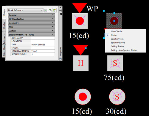
Notification Device Symbols 2.0
I used the same style from the detector blocks for the notification block. I made it so the block could be easily changed from different types of notification devices in a matter of a few clicks. Now you could change from a wall mounted device to a ceiling mounted device, even from a horn strobe to a speaker strobe with the use of the dynamic block list.
Again using attributes I was able to quickly add accessories and Candela levels to the block.
3 notes
·
View notes
Text
Initiating Device Symbols 2.0
After dealing with the head aches of incomplete backgrounds or only receiving PDF versions I found a way to get the symbols I constantly use to stand out and be easily seen. Below is a screen capture showing the dynamic block I created for the detectors commonly used in the drawings. These detector symbols are all part of one block that can filter different views to change the look of the block as seen with the drop down list. I created a hatch for the background of each detector type so now I can just place the block on part of a plan and be seen with out the need of doing a wipe out when it is placed over another object.
Within this block are attributes where labels can be placed to show if the particular detector has a detector guard or is new/existing. Also I can label the detector to show what room it is located in along with the "address" or digital signature it has showing it in the fire alarm control panel program.
All of these attributes can be edited at the same time if need be just by highlighting the necessary blocks and editing the labels in the properties dialog box. So if I need to show that a string of 20 smoke detectors have a sounder base accessory I can highlight them and simple type "SB" in the Accessory label and they will all be change in one step instead of highlighting them and changing them individually.

1 note
·
View note
Text
AggravatingCAD - Plotting to PDF
Autocad is a great program. It's revolutionized the engineering process all over the world. With that said it can be very frustrating at time when it doesn't work properly and does things that make you want to throw your computer out of a window. Earlier I mentioned Wiring Diagrams and how I would put together a group of these diagrams in a layout as part of a project plan set. Now that I was done with the design I needed to plot to PDF to send the whole drawing set to a client or engineer. Autocad has struggled over the years to do this function. If the PDF is going to be over a certain amount of pages it has to be broken up or Autocad will crash (I learned this the hard way.) It didn't seem to matter how fast or good the computer was Autocad just didn't like plotting to PDF. On top of all that it seemed when ever I plotted the Wiring diagram sheet to PDF it would open in a PDF viewer with font errors.
After hours of trying to fix this problem that only seemed to affect my wiring diagrams I decided to change the standard font in the Autocad template I used. Instead of using the Arial font I changed over to Times New Roman. Still didn't help, I kept getting the same error. That's when I decided to search for a new PDF printer instead of the default one for Autocad. After searching I found a PDF printer called Bullzip PDF Printer. It has it's glitches as well but once you get familiar on how to set it up it printed very fast and fixed the issue I was having with the default printer. The one downside is now I have to print the Wiring Diagrams to PDF separately from the rest of the drawings and insert it into the plan set later which does create an extra step. So until improvements are made I'll just have to deal with it.
0 notes
Text
Wiring diagrams, PDF's and converting drawings - Oh my!
Another part of the package put together for the contractor installing the devices on the projects are wiring diagrams. Wiring Diagrams show how the devices are connected to the fire alarm or security system. Some wiring diagrams are better than others. Most of the brands we use provide the installation instructions with their product in PDF format. Inserting 20 different PDF's into a drawing makes it a large file and slows down the potting process. In order to avoid this I needed a way to convert the PDF drawings into DWG file format WITH OUT having to redraw every single diagram for each device. So I went to my best friend the internet and searched for ways to do this. Then I came across the best conversion site, Cometdocs.com. I normally don't gush about sites but this one was a huge time saver and free!. I was able to upload any non-scanned PDF's and convert them to DWG's, Excel, etc. So now any PDF'd drawings I needed to use as a background could be converted so I could manipulate them and delete what I didn't need. Converting all the wiring diagrams now took a couple of days instead of weeks.
1 note
·
View note
Text
Show me the power....loss!
Part of fire alarm design involves Voltage Drop Calculations. These calculations are to make sure that the fire alarm system has enough power to run the notification devices (I.E. horns and strobes) that alert the public that there is a fire. This information is used to make sure the buildings fire alarm can still function for a certain amount of time even in the event of power loss.
It sounds very technical and it is, but thanks to the help of the internet I was able to find an Excel spreadsheet that would help show the design shown on the plans will meet the expected standards according to the NFPA and any local fire department regulations.
Essentially I plug the candela values of the strobe devices along with their relative distance from their power source and the spreadsheet calculates the values. It's a clean and straight forward way to show what battery power will be needed in a building.

0 notes
Text
The dynamic beauty of blocks.
While designing the layout for a buildings' fire alarm a lot of things can change.A room that was originally a storage room is now a boiler room. That means that the smoke detector that was there now has to be a heat detector. These kind of things happen all the time and changing the type of detector from one to another means I have to switch out blocks. Erasing the the current block and inserting a new one is a lot of steps if you need to do it all the time.Shortcuts are your friend in this line of work. Dynamic blocks were created to make drafters less cranky after receiving a bunch of red-lines or list of changes. Since I was using my own version of autocad and not the LT version supplied by my office I could create dynamic blocks and easily make it so I could change a Duct detector into a Heat detector or a wall mounted horn strobe into a ceiling mounted strobe in the matter of seconds. I could now even select a bunch of blocks at a time and change them all at once or I could change the rotation of a horn strobe to face the proper location with the ease of a single click.

0 notes
Text
Improvising is a necessary drafting skill....
Many of the projects we worked on involved old schools or residential buildings where the original blue prints were not available in autocad format or there were clients who didn't know the difference between a PDF and a DWG. So in the instances I received a PDF of a floor plan to use as a background, especially a poorly scanned one I was not amused. A PDF of a background or floor plan meant I could not turn off unwanted layers and that I was stuck with plan that would become even harder to read and the current symbols I was using would get lost in the mix if they were placed in an area where another object already was.
Thankfully Autocad has a function called "Wipeout" where you can create a shape over an area of a drawing and block it from being seen. Then you can place items in the wiped out section so they are clearer to see. The downside to this is that you would have to do it for each device that is obscured and can be very time consuming trying to get the wipeout to only cover certain parts of a busy drawing. It can also make the drawing file size bigger and more prone to crashing or making the printing/publishing extremely long. I needed to find a faster way.
1 note
·
View note
Text
Symbols 1.0
While tinkering with the symbols that were available to me and learning how fire alarm and security systems were installed and what the main components were I tried several looks and found what worked and what didn't through trial and error. My main goal was to make it easy to understand the plan for the electrical contractor, reviewer, architect, who ever was to look at it. I also looked for ways to speed up the edits or changes made to the plan.
Unfortunately the symbols I was working with didn't make that possible. The symbols didn't really stand out so if you had a busy plan with a lot of dimensions and other items it was easy to over look a smoke detector or module which could lead to mistakes and devices not getting installed.

0 notes
Text
Some one give me a sign, a symbol....something!
Since I was new to the Fire Alarm and Security industry I wasn't yet familiar with NFPA72 (National Fire Alarm Code) or the symbols associated with the plans. When I looked at the older plans I saw the various symbols for smoke detectors, heat detectors and duct detectors, they were all different and there didn't seem to be a set standard look. After seeing plans from other electrical contractors, looking at the NFPA standard symbols and asking the engineers in my office on what our symbols should look like I didn't really get any feed back. So I continued using the symbols we had, but after awhile I realized these symbols were bland and annoying to work with. The symbols were all individual shapes with text sitting next to them. If I needed to move a symbol I had to make sure I "grabbed" all of the lines and shapes that made up that symbol and remember to move the associated text as well..
If you look at the image below you can see the objects that have the blue boxes are the selected objects and that nothing is one unit. Making any edits to one or multiple objects was time consuming.

After a while this became very tedious so I started to convert all the symbols into "blocks". Now all the lines were connected together and were all one unit. http://www.autodesk.com/solutions/cad-blocks
This started the evolution of the look and feel of the drawings.
0 notes
Text
CAD Standards, who has standards nowadays?
In all my years as a CAD drafter I still to this day have never been at a job where the engineering department had CAD standards. I've always had to make them up as I went. This position was no different. After finally looking over some drawings and seeing the set up I realized that I'd have to re-vamp the drawing set up and update the company title block.
All the drawings were done as separate files. So the 1st floor plan and the 2nd floor plan were 2 separate drawings and both were set up with the title block in "model" space. That meant that when I went to go print the plans I would have to open each drawing and print them one at a time. If I had a project with 10 floors this set up would take me up to an hour to print because I would have to open every drawing. Who has time for that?
I updated the title block so that the company logo would show up (every company likes branding). Then I made it so the title block was in "paper space" so that now the title block and sheet could be copied or plotted by simply using the appropriate tab (similar to Excel).
With that done I would take the floor plans for the project and insert them as backgrounds into the one file and do all the necessary changes in one file instead of three. This method is very effective unless you have an absurd amount of drawings to deal with.
The next step was to update the symbols and block library.

0 notes
Text
Autocad shouldn't be done "lightly".
My first hurdle was the version of Autocad being used was Autocad 2010 LT. If you are unfamiliar with Autocad this is the"light" version of Autocad which didn't have all the features a drafter might be used to. Certain functions that would make me faster and more efficient were not available and since Autocad is expensive the company did not want to spend money on upgrading.
After my previous job I went out and bought my own copy of a full version of Autocad complete with 3D design. I was able to get a reasonably cheap version on Ebay. I was familiar with that software, especially the "Sheet Set Manager" which streamlined printing and publishing of the plans. There was no way I could go back to not using that feature so I brought my copy of Autocad in and installed it. None of my supervisors seemed to care and probably won't until I am no longer around. Now most companies would probably object to me bringing in and using my own software for valid reasons. It doesn't bother me since I already had the software and it makes my job easier. If my job is easier I am more productive. I like being productive. It's sick I know......
0 notes
Text
In the beginning there was confusion....
When I first started working as a Fire Alarm Designer I looked at previous jobs that were done so I could get an idea of what was expected of me. Keep in mind that there was only one CAD drafter in the office and now that was me.
The problem was that I had no idea where to look for the drawings because the ALL of the job folders were abbreviated so that the only person who knew how to find the job was the previous Drafter that I had replaced. So a job folder would be labeled 123MNST had no meaning to the engineer or anyone else looking for the drawings folder. So if the drafter had gone on vacation and someone needed to look at a plan for 123 Main St, New York the odds of them finding said folder were low.
Now other than job security reasons I could not understand this method of job folder labeling. So for the first couple of days I spent my time decoding the job folders and making it so that anyone in the office could find the drawings, PDF's and any other info that may pertain to the engineering of any job. So instead of getting 123MNST the was a folder labeled 123 Main St - New York (Job# 12345). No decoder ring necessary.

0 notes