
Don't wanna be here? Send us removal request.
Statistics
We looked inside some of the posts by keroblin-physicalcomputing and here's what we found interesting.
Average Info
Notes Per Post
0
Likes Per Post
0
Reblog Per Post
0
Reply Per Post
0
Time Between Posts
23 hours
Number of Posts By Type
Text
17
Last Seen Tumblr Blogs


Fun Fact
Tumblr has been providing a Korean-language service since 2013.
Text
Links to experiment files
this link provides access that is synced to my files so they may be out of date while they upload, but will have version history if that is something that interests you.
This version is up to date but is a direct upload that does not contain version history.
0 notes
Text
Final Updates
Initially, I needed to set up the LDR task detection again, however I faced issues where I thought that the black pencil would omit enough light reflection to trigger things but it did not. I then used an LED to light underneath the spinner, which also did not work. So then, as a last resort, I settled on the user having to hole punch the start of each task (though I did not have time to set up tasks ending) so that the light would shine through to the LDR.
Unfortunately, I ran into an issue where the project was using to much memory and creating encrypted characters and unicode instead of english characters. I knew this was the source of the issue where I had disregarded the high memory warning before as I happen to know about the glitch in PAC-MAN where a high memory usage destroys their custom characters. I found the most efficient way to reduce the memory was, as it was not using its whole functionality, removing the Keyframe class and using the custom character's integer value instead.
I then split the checkChoice function into checkChoice and printState which did two different things so we were not always checking for the button input. I did not create a new question class but instead implemented the question screenState and each of the 3 button's respective answer states into the function parameters for checkChoice so that it would know what state to trigger after each response and what the initial state was. This was not printing correctly to start with as it was using its own printing functionality, so I moved the cursor setting for the button prompts into printState and used a boolean called boolean isChecking (set within checkChoice depending on if we have selected anything) to ensure these are only drawn when a question is in progress. Alongside this, I noticed that the clock was in fact moving the wrong way so changed the setupMoveInSteps(1) to -1 so it would go backwards.
I then ran into an issue where the state after the question would not clear so I made the boolean hasResponded as well as another time counter to play the response state for a specified time before clearing the answer variables and returning the state to default.
Unfortunately, something caused the response animations not to play from this point onward. While I am still unsure of the exact issues, I knew it was tied to the as aforementioned isChecking variable as this cancelled some settings in the printState function. This is an issue as the isChecking boolean was not set to false until after we had responded so it must not have set. This was the solution that seemed to work:
I did notice by this point, however that the speaker wasn't working and remembered my tutor mentioning that components of the input pins need to share a common ground. So unfortunately, the new speaker I received must just be one that pulls a higher current than the old one and I do not at this time have the ability to gain a new one. I had to place it back into the ground that meant the brightness of the screen reduced. If ever you try this, you should not face this issue! If you can use a board with more input pins however definitely do!
(Note: I have been unable to simulate production pet through TinkerCad as it does not allow easily for custom .cpp and header files, so I am using screenshots in their place)
Evaluation
While I am proud that the project works and I enjoy the concept and believe it beneficial to users, I understand it is lacking some precision without tracking the ends of tasks and also the build allows for other light to easily get in through the day which could cause issues with task detection. A solution to the latter would be to build suitable housing but also to reset the neutral light calibration every hour based on if we're in a task already or not, or even to add a recalibration button. I also believe that the build is a little messy and could be cleaned with cable ties, better board optimisation and other components to clear free ports. If I could do this over, I would have chosen to use a higher resolution LCD to fit more words onto for better questions and overall user experience.
The final code is below:
#include
#include
#include "pitches.h"
#include "ScreenSet.h"
////sounds
int taskEnding[2] = { NOTE_G5, NOTE_B5 }; int endDur[2] = { 2,2 }; int buttonPress[2] = { NOTE_E2, NOTE_A2 }; int pressDur[2] = { 4,4 }; int sad[2] = { NOTE_B2, NOTE_F1 }; int noteDurations[2] = { 4,4 };
unsigned long currentTime; unsigned long prevTime; int interval = 21;
const int speakerpin = 8;
const int LEDPIN = A1; const int LDRPIN = A0; int light; int neutral; int dark; int bright; bool isNeutralSet; bool inTask = false; bool prevTaskState = false; bool hasResponded = false; bool hasPrinted = false; const int MOTOR_IN1_PIN = A2; const int MOTOR_IN2_PIN = A3; const int MOTOR_IN3_PIN = A4; const int MOTOR_IN4_PIN = A5; const int STEPS_PER_REVOLUTION = 2048; TinyStepper_28BYJ_48 stepper;
////sprites byte none[8] = { // Array of bytes B00000, // B stands for binary formatter and the five numbers are the pixels B00000, B00000, B00000, B00000, B00000, B00000, B00000 };
byte hamster[8] = { // Array of bytes B10001, // B stands for binary formatter and the five numbers are the pixels B11111, B10101, B11011, B11111, B11011, B10101, B11111 };
byte sleepHam[8] = { // Array of bytes B00000, // B stands for binary formatter and the five numbers are the pixels B11111, B00100, B11011, B11111, B11011, B10101, B11111 };
byte shockHam[8] = { // Array of bytes B11011, // B stands for binary formatter and the five numbers are the pixels B10101, B10101, B11011, B11111, B11011, B11011, B11111 }; byte sadHam[8] = { // Array of bytes B10001, // B stands for binary formatter and the five numbers are the pixels B11111, B10101, B01110, B11011, B11111, B10001, B10101 };
byte button[8] = { B01110, B11111, B11111, B01110, B00000, B00000, B00000, B00000 };
const int b1Pin = 6; int b1State = 0; const int b2Pin = 9; int b2State = 0; const int b3Pin = 10; int b3State = 0;
int choice = 0;
////animation instantiation
int keyframes[6] = {1,2}; int questionFrames[6] = {1, 3}; int yesFrames[6] = {1}; int noFrames[6] = {4}; int maybeFrames[6] = {2}; int defaultKeys[6] = {1,2}; Anim anim0(defaultKeys, true); Anim anim1(keyframes, true); Anim question(questionFrames, true); Anim yesAnim(yesFrames, true); Anim noAnim(noFrames, true); Anim maybeAnim(maybeFrames,true); ScreenState defaultState("default", anim0); ScreenState taskQuestion1("breaktime?", question); ScreenState taskQuestion2("doing ok?", question); ScreenState y("Nice one!", yesAnim); ScreenState n("Try to break!", noAnim); ScreenState m("Thats ok!", maybeAnim); ScreenState currentState = defaultState; ScreenState printedState; LiquidCrystal lcd(12, 11, 5, 4, 3, 2); int currentSprite; bool isChecking = false;
unsigned long taskPrevTime; unsigned long questionDelay = 5000; unsigned long taskAnimPrevTime; unsigned long taskUnsetDelay = 2500;
void setup() { pinMode(speakerpin, OUTPUT); pinMode(LDRPIN,INPUT); pinMode(LEDPIN, OUTPUT); analogWrite(LEDPIN, 255); Serial.begin(9600); stepper.connectToPins(MOTOR_IN1_PIN, MOTOR_IN2_PIN, MOTOR_IN3_PIN, MOTOR_IN4_PIN);
pinMode(b1Pin, INPUT); pinMode(b2Pin, INPUT); pinMode(b3Pin, INPUT); lcd.begin(16,2); // Initializes the interface to the LCD screen, and specifies the dimensions (width and height) of the display } lcd.createChar(0, none); //creates a custom character lcd.createChar(1, hamster); //creates a custom character lcd.createChar(2, sleepHam); //creates a custom character lcd.createChar(3, shockHam); lcd.createChar(4, sadHam); lcd.createChar(7, button); lcd.clear();
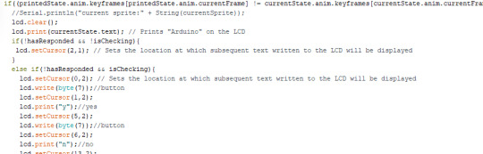
printedState = defaultState; } void printState(){ currentSprite = currentState.anim.keyframes[currentState.anim.currentFrame];
if((printedState.anim.keyframes[printedState.anim.currentFrame] != currentState.anim.keyframes[currentState.anim.currentFrame]) || (currentState.anim.keyframes[currentState.anim.currentFrame] == 0) || currentState.text != printedState.text){ //Serial.println("current sprite:" + String(currentSprite)); lcd.clear(); lcd.print(currentState.text); // Prints "Arduino" on the LCD if(!hasResponded && !isChecking){ lcd.setCursor(2,1); // Sets the location at which subsequent text written to the LCD will be displayed } else if(!hasResponded && isChecking){ lcd.setCursor(0,2); // Sets the location at which subsequent text written to the LCD will be displayed lcd.write(byte(7));//button lcd.setCursor(1,2); lcd.print("y");//yes lcd.setCursor(5,2); lcd.write(byte(7));//button lcd.setCursor(6,2); lcd.print("n");//no lcd.setCursor(13,2); lcd.write(byte(7));//button lcd.setCursor(14,2); lcd.print("m");//maybe lcd.setCursor(16,1); } lcd.write(byte(currentSprite)); lcd.noCursor(); // Hides the LCD cursor } printedState = currentState;
if(currentState.anim.currentFrame < 5 && currentState.anim.currentFrame >= 0 && (currentTime - prevTime >= currentState.anim.interval)){ prevTime = currentTime; if(currentState.anim.keyframes[currentState.anim.currentFrame+1] != 0){ currentState.anim.currentFrame++; } else if(currentState.anim.isLooping){ currentState.anim.currentFrame = 0; } } }
void checkChoice(ScreenState questionState, ScreenState state1, ScreenState state2, ScreenState state3){ Serial.println("checkingchoice"); b1State = digitalRead(b1Pin); b2State = digitalRead(b2Pin); b3State = digitalRead(b3Pin); if(b1State == HIGH){ choice = 1; playsound(taskEnding, endDur); currentState = state1; taskAnimPrevTime = currentTime; hasResponded = true; } else if(b2State == HIGH){ choice = 2; playsound(taskEnding, endDur); currentState = state2; taskAnimPrevTime = currentTime; hasResponded = true; } else if(b3State == HIGH){ choice = 3; playsound(taskEnding, endDur); currentState = state3; taskAnimPrevTime = currentTime; hasResponded = true; } else if(choice == 0){ currentState = questionState; } }
void loop() { digitalWrite(speakerpin, HIGH);
currentTime = millis(); stepper.setSpeedInStepsPerSecond(2.1); stepper.setAccelerationInStepsPerSecondPerSecond(2.1); stepper.setCurrentPositionInSteps(0); stepper.setupMoveInSteps(-1); stepper.processMovement(); while(!stepper.motionComplete()) { currentTime = millis(); printState(); checkForTask(); stepper.processMovement(); } printState(); checkForTask(); }
void checkForTask(){ if(isChecking && !hasResponded){checkChoice(taskQuestion1, y,n,m);} if(!isChecking){ if(inTask && (currentTime - taskPrevTime >= questionDelay) && !hasResponded){ playsound(buttonPress, pressDur); isChecking = true; } if(!isNeutralSet){ neutral = analogRead(LDRPIN); Serial.print("neutral value: "); Serial.println(neutral); isNeutralSet = true; } light = analogRead(LDRPIN); //Serial.println(light); if(!inTask && light > neutral + 3 && !inTask){ Serial.print("task detected \n"); inTask = true; } else if(inTask && light <= neutral && inTask){ Serial.print("task ended or no task \n"); inTask = false; }
}
if(hasResponded){ Serial.println("hasResponded"); taskPrevTime = currentTime; isChecking = false; if(currentTime - taskAnimPrevTime >= taskUnsetDelay){ Serial.println("clearedchoice"); lcd.clear(); choice = 0; currentState = defaultState; hasResponded=false; } } }
void playsound(int melody[], int durations[]){ int noteNum = sizeof(melody); for (int thisNote = 0; thisNote < noteNum; thisNote++) { int noteDuration = 1000 / noteDurations[thisNote]; tone(speakerpin, melody[thisNote], noteDuration); int pauseBetweenNotes = noteDuration * 1.30; delay(pauseBetweenNotes); noTone(8); } }
Updated ScreenSet.cpp
#include "Arduino.h"
#include "ScreenSet.h"
Anim::Anim(){} Anim::Anim(int keys[6], bool isLooping){ for(int i = 0; i < 6; i++){ this->keyframes[i] = keys[i]; } this->isLooping = isLooping; } ScreenState::ScreenState(){} ScreenState::ScreenState(String text, Anim animation){ this->text = text; this->anim = animation; }
Updated ScreenSet.h
#include <"Arduino.h">
#ifndef ScreenSet_h
#define ScreenSet_h #include <"Arduino.h">
class Anim{ public: Anim(); Anim(int keys[6], bool isLooping); int currentFrame = 0; bool isPlaying; unsigned long interval = 500; //frames per second bool isLooping = true; //if the animation loops int keyframes[6]; private: };
class ScreenState{ public: ScreenState(); ScreenState(String text, Anim animation); bool isPlaying; String text; Anim anim; private: };
#endif
0 notes
Text
Update - Physical end mostly done!
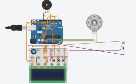
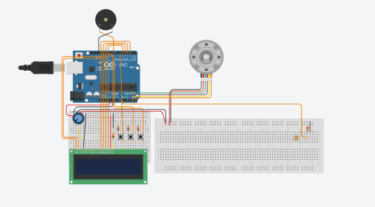
As mentioned in the above videos, the physical component setup is effectively done! While I did not have enough pins for the colour sensor, I have used some leads for the LDR to sit inside of the cardboard build. I have also fixed a noticed issue where because I was siphoning power from the main 5v line in the breadboard, the stepper was taking on too much current and underpowered the LCD causing it to become darker. Anton donated a mains power supply which I am now using to power the stepper in isolation so that it does not interfere with the main board.
The code used in this test uses the ScreenSet.cpp and ScreenSet.h I created for the LCD Interaction test as well as pitches.h from the ToneMelody example I used for the speaker. This is so I can animate the screen and play sounds.
These are running their respective functions both in the main loop and the "while(!stepper.motionComplete())" loop as otherwise they would stop while the stepper is in motion. I made the animation code from the LCD Interaction into a function as well as the sound playing code from ToneMelody so that they could be called in a more readable way. I did, however, add a check in the animation code so that it would only print new data to the LCD if the state we wanted to print did was not already print this. I did this by storing the currentState into another ScreenState called printedState. I then checked the current spriteNum against the one in currentState. currentState is set after the button choice is made and before the printedState is set so printedState is always the old one.
The new file is called Production_Pet and pulls together most of the code for experiments up until this point.
The only area left to work on is new task detection on the spinner, which I will likely do by punching holes and using an LED on male to female leads, like the LDR, so that I can more freely position it under the build and get it in an effective position for the LDR to read the lighting status. I also need to add in the states and choice prompts for the questions so that you can respond to the pet which I feel confident about creating as unique screenstate classes that have button prompts within and sprites for yes, no and sort of, maybe as faces nodding, shaking and tilting
New code below:
include
include // includes the LiquidCrystal Library
include "pitches.h"
include "ScreenSet.h"
////sounds
int taskEnding[2] = { NOTE_G5, NOTE_B5 }; int endDurations[2] = { 2,2 }; int buttonPress[2] = { NOTE_E2, NOTE_A2 }; int pressTone[2] = { 4,4 }; int sad[2] = { NOTE_B2, NOTE_F1 }; int noteDurations[2] = { 4,4 };
unsigned long currentTime; unsigned long prevTime; int interval = 21;
const int speakerpin = 8; const int LDRPIN = A0; int light; int neutral; int dark; int bright; bool isNeutralSet; bool inTask = false;
const int MOTOR_IN1_PIN = A2; const int MOTOR_IN2_PIN = A3; const int MOTOR_IN3_PIN = A4; const int MOTOR_IN4_PIN = A5; const int STEPS_PER_REVOLUTION = 2048; TinyStepper_28BYJ_48 stepper; bool hasPrinted = false;
////sprites byte none[8] = { // Array of bytes B00000, // B stands for binary formatter and the five numbers are the pixels B00000, B00000, B00000, B00000, B00000, B00000, B00000 };
byte hamster[8] = { // Array of bytes B10001, // B stands for binary formatter and the five numbers are the pixels B11111, B10101, B11011, B11111, B11011, B10101, B11111 };
byte sleepHam[8] = { // Array of bytes B00000, // B stands for binary formatter and the five numbers are the pixels B11111, B00100, B11011, B11111, B11011, B10101, B11111 };
byte shockHam[8] = { // Array of bytes B11011, // B stands for binary formatter and the five numbers are the pixels B10101, B10101, B11011, B11111, B11011, B11011, B11111 }; byte sadHam[8] = { // Array of bytes B10001, // B stands for binary formatter and the five numbers are the pixels B11111, B10101, B01110, B11011, B11111, B10001, B10101 };
byte tear[8] = { // Array of bytes B00000, // B stands for binary formatter and the five numbers are the pixels B00100, B01010, B10001, B10001, B01110, B00000, B00000 }; byte shockLines[8] = { // Array of bytes B00011, // B stands for binary formatter and the five numbers are the pixels B01100, B10000, B00000, B01111, B00000, B11000, B00111 }; byte button[8] = { B01110, B10001, B10001, B01110, B00000, B00000, B00000, B00000 }; const int b1Pin = 6; int b1State = 0; const int b2Pin = 9; int b2State = 0; const int b3Pin = 10; int b3State = 0;
int choice = 0;
////animation instantiation
KeyFrame frame0(0); KeyFrame frame1(1); KeyFrame frame2(2); KeyFrame keyframes[6] = {frame1,frame2}; KeyFrame defaultKeys[6] = {frame0}; Anim anim0(defaultKeys, false); Anim anim1(keyframes, true); ScreenState defaultState("default", anim0); ScreenState state1("state1", anim1); ScreenState state2("state2", anim1); ScreenState state3("state3", anim1); ScreenState taskQuestion("how is your task going?", hamster); ScreenState currentState; ScreenState printedState; LiquidCrystal lcd(12, 11, 5, 4, 3, 2); // Creates an LCD object. Parameters: (rs, enable, d4, d5, d6, d7) int currentSprite; bool isChecking = false;
void checkChoice(){ b1State = digitalRead(b1Pin); b2State = digitalRead(b2Pin); b3State = digitalRead(b3Pin); if(b1State == HIGH){ choice = 1; //Serial.println("1"); currentState = state1; } else if(b2State == HIGH){ choice = 2; //Serial.println("2"); currentState = state2; } else if(b3State == HIGH){ choice = 3; //Serial.println("3"); currentState = state3; } else if(choice == 0){ currentState = defaultState; }
currentSprite = currentState.anim.keyframes[currentState.anim.currentFrame].spriteNum;
if(printedState.anim.keyframes[printedState.anim.currentFrame].spriteNum != currentState.anim.keyframes[currentState.anim.currentFrame].spriteNum){ //Serial.println("current sprite:" + String(currentSprite)); lcd.clear(); lcd.print(currentState.text); // Prints "Arduino" on the LCD lcd.setCursor(2,1); // Sets the location at which subsequent text written to the LCD will be displayed lcd.write(byte(currentSprite)); lcd.noCursor(); // Hides the LCD cursor } printedState = currentState;
if(currentState.anim.currentFrame < 5 && currentState.anim.currentFrame >= 0 && (currentTime - prevTime >= currentState.anim.interval)){ prevTime = currentTime; if(currentState.anim.keyframes[currentState.anim.currentFrame+1].spriteNum != 0){ currentState.anim.currentFrame++; } else if(currentState.anim.isLooping){ currentState.anim.currentFrame = 0; } } }
void setup() { pinMode(speakerpin, OUTPUT); pinMode(LDRPIN,INPUT); Serial.begin(9600); stepper.connectToPins(MOTOR_IN1_PIN, MOTOR_IN2_PIN, MOTOR_IN3_PIN, MOTOR_IN4_PIN);
pinMode(b1Pin, INPUT); pinMode(b2Pin, INPUT); pinMode(b3Pin, INPUT); lcd.begin(16,2); // Initializes the interface to the LCD screen, and specifies the dimensions (width and height) of the display } lcd.createChar(0, none); //creates a custom character lcd.createChar(1, hamster); //creates a custom character lcd.createChar(2, sleepHam); //creates a custom character lcd.createChar(3, shockHam); lcd.createChar(4, sadHam); lcd.createChar(5, tear); lcd.createChar(6, shockLines); lcd.createChar(7, button); lcd.clear();
printedState = defaultState; }
void loop() { digitalWrite(speakerpin, HIGH);
currentTime = millis(); stepper.setSpeedInStepsPerSecond(0.0021); stepper.setAccelerationInStepsPerSecondPerSecond(0.0021); stepper.setCurrentPositionInSteps(0); stepper.setupMoveInSteps(1); stepper.processMovement(); checkForTask(); while(!stepper.motionComplete()) { currentTime = millis(); if(isChecking){ checkChoice(); } checkForTask(); if(!hasPrinted){ Serial.println("isMoving"); //playsound(sad, noteDurations); hasPrinted = true; } stepper.processMovement(); } if(isChecking){ checkChoice(); } checkForTask(); Serial.println("finishedLoop………………………….."); hasPrinted = false;
}
void checkForTask(){ if(!isNeutralSet){ delay(100); neutral = analogRead(LDRPIN); Serial.print("neutral value: "); Serial.println(neutral); isNeutralSet = true; }
light = analogRead(LDRPIN);
Serial.println(light);
if(light < neutral - 6 && !inTask)
{ Serial.print("task detected \n");
inTask = true;
}
else if(light >= neutral && inTask)
{ Serial.print("task ended or no task \n");
inTask = false;
}
}
void playsound(int melody[], int durations[]){ int noteNum = sizeof(melody); for (int thisNote = 0; thisNote < noteNum; thisNote++) {// to calculate the note duration, take one second divided by the note type. //e.g. quarter note = 1000 / 4, eighth note = 1000/8, etc. int noteDuration = 1000 / noteDurations[thisNote];
tone(speakerpin, melody[thisNote], noteDuration); // to distinguish the notes, set a minimum time between them. // the note's duration + 30% seems to work well: int pauseBetweenNotes = noteDuration * 1.30;
delay(pauseBetweenNotes);
// stop the tone playing: noTone(8);
} }
0 notes
Text
Steppers and Servos
Servos only work across 180 degrees, while steppers work across the whole 360 degrees. Servos have a coordinate system where they can move to specified angles, where stepper motors can only move based on steps provided to them (my library for my stepper allows this luckily!).
Servos move based on a train or pulses over time, so a pulse with a length of 1.5ms forces the servo to move to the 90 degrees position. Servos contain a 'permanent magnet DC motor with an internal tachometer'. A tachometer is used to track the speed of a moving object and a permanent magnet DC motor is used to add force to the armature of the servo based on the magnetic field strength. The tachometer keeps track of the speed and the driver processes if the servo doesn't have enough power for the desired speed and provides more.
Stepper motors are different in that they work based on steps of the full rotation instead of angles. The mechanism is similar, using poles of a magnet to provide force, but there is no feedback (like a tachometer). My one uses 4 coils and therefore needs 4 wires (plus power and ground). It has its own control chip and needs and male to female lead to provide the input and power to each coil of the stepper. Arduino tells the stepper, through a library (in my case this one). The coils are powered in a sequence to rotate the central magnet. It is used for precision devices like CNC machines and DVD players.
More information is linked below:
0 notes
Text
How an LCD Works
A liquid crystal display, or LCD, produces images based on electrical information. The panel itself is backlit to produce light with a polarizing filter, where the crystals allow the light to shine through more vividly by rotating to change the light's direction. Polarizing filters are used commonly in things like ATMs for privacy: you can only see the screen from the front. They only allow the light which is moving in a certain direction to pass through them. From TVs to calculators and even toys, LCDs are used as they produce no burn-in which allow devices that need long term image display to work effectively.
0 notes
Text
How a Speaker Works
A speaker, which I have been using for sounds in my device, is a component that vibrates based on the voltage passing through it. In order to change the pitch of the sound, Arduino provides an example pitch header file that contains many octaves and notes laid out like a music tracker software. These generate square waves (binary sound, either on or off for a length). To use them we select them in an array before passing into their for loop. In my final device, I made this a function. I have talked about the code workings of this in a previous post.
The coil within the speaker moves (vibrates) around the magnet within based on the current sent to it, so in our case, for a song, we send a high current for a specified length of time for a high note, and a lower current for a low note. The sound is produced by the cone being moved based on the vibration and pushing and pulling the air creating waves of pressure and producing the sound.
The diagram is from the link below it, which provides more detailed information:

0 notes
Text
How an LDR works
A light dependent resistor, or LDR, is a resistor that works via a chemical reaction. The wavy line atop the component reacts to light, it is actually a cadmium sulphide line, which becomes less conductive based on light. According to wikipedia, this reaction also releases hydrogen!
LDRs are used in many applications, especially where we have to control the brightness of a light based on the ambient light around it.
To use the LDR in my projects, I have been using a potential divider circuit which means that we can track the difference in voltage over time so we can use it in code. We have to also convert the output voltage from it into an analog read in the A0 pin for smoothness and accuracy as a digital read is staired.
0 notes
Text
How a Button Works
There are several types of push buttons, however the one I have been working with is a momentary contact, normally-off switch. This means that it only allows current when the button is pushed. However, a momentary contact, normally-on switch would do the opposite: it would allow current only when it isn't pushed.
There are contacts inside of the button, as well as springs. When you push, the springs move so the contacts press into each other, the contacts touch and the current can pass through.
https://www.techwalla.com/articles/how-does-a-momentary-switch-work
0 notes
Text
How a Potentiometer Works
A potentiometer is a device that controls the level of current going through the circuit via moving a wiper along a resistive track, effectively changing its own resistance. When you turn the potentiometer, you are changing the amount of resistance effecting the voltage into the middle wire (output). It is used in dimmer switches, volume knobs, and other twisting dials.
The link below provides more detail:
0 notes
Text
Animation Framework
In order to create a friendly and reactive experience with the character, I needed to create several screen states that would react based on your tasks and inputs. To do this, I programmed several classes: one for keyframes that holds byte sprites' created char's numbers as integers (explained in another post), one for animations that hold keyframes and speed and one for screen states that hold animations and text to display.
I felt the need to do this to keep code tidy and secure as I go later into development where there will be many different functions for different things.
I had some problems through the process however, such as an issue where the currentSprite would add to its max number in a for loop that was supposed to add to the currentFrame of the animation, generating random unicode as sprites. However, I fixed this where I did not consider the maximum length of the array of the keyframes on the animation of the screenstate as I didn't set a constant length for the array. I solved this by setting them as a maximum of 6 keyframes in the array as I felt this was a generous enough number, and simply did not play any sprites where their spriteNum was set to "0" (a byte sprite I made to light nothing).
The process videos and demonstration are available here.
Object Oriented Programming: An Overview (code below!)
I have used "object oriented programming" for this which I am familiar with as it is used heavily in game engines. Each "object" of a class has its own values for the class' parameters. For example, a human needs to have hair, eyes, skin, bones and nails (hear me out!) so the "human" class has these variables in it. Every human is an object of this class, however parts of them can change either from birth or later down the line.
Classes use constructors to set variables from their initialisation (birth). For humans, the hair colour, eye colour and skin colour would be set in a constructor. But all humans need the same bones so we initialise their variable in the class itself. We can change variables after the fact (like nail colour and hair colour) by accessing the class object's variables. Our human can be called Naomi for example and she derives from the human class.

To access her variables we can reference her name after construction in the main script: naomi.nails = blue. But where classes hold other class objects, like our animation object holding keyframes, we can reference the class object variable from within the object. In this case, imagine hair is another class that holds variables for length, colour and health. To access these we use: naomi.hair.color = red.
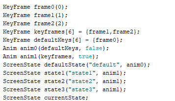
Instantiating another class object from within a class is not too difficult. We treat it like a variable, like this:
Here is the code for the system:
LCD_Interaction:
#include // includes the LiquidCrystal Library
#include "ScreenSet.h"
byte none[8] = { // Array of bytes B00000, // B stands for binary formatter and the five numbers are the pixels B00000, B00000, B00000, B00000, B00000, B00000, B00000 };
byte hamster[8] = { // Array of bytes B10001, // B stands for binary formatter and the five numbers are the pixels B11111, B10101, B11011, B11111, B11011, B10101, B11111 };
byte sleepHam[8] = { // Array of bytes B00000, // B stands for binary formatter and the five numbers are the pixels B11111, B00100, B11011, B11111, B11011, B10101, B11111 };
const int b1Pin = 6; int b1State = 0; const int b2Pin = 9; int b2State = 0; const int b3Pin = 10; int b3State = 0;
int choice = 0;
KeyFrame frame0(0); KeyFrame frame1(1); KeyFrame frame2(2); KeyFrame keyframes[6] = {frame1,frame2}; KeyFrame defaultKeys[6] = {frame0}; Anim anim0(defaultKeys, false); Anim anim1(keyframes, true); ScreenState defaultState("default", anim0); ScreenState state1("state1", anim1); ScreenState state2("state2", anim1); ScreenState state3("state3", anim1); ScreenState currentState; LiquidCrystal lcd(12, 11, 5, 4, 3, 2); // Creates an LCD object. Parameters: (rs, enable, d4, d5, d6, d7) int currentSprite; unsigned long currentTime; unsigned long prevTime; void setup() { Serial.begin(9600); pinMode(b1Pin, INPUT); pinMode(b2Pin, INPUT); pinMode(b3Pin, INPUT); lcd.begin(16,2); // Initializes the interface to the LCD screen, and specifies the dimensions (width and height) of the display } lcd.createChar(0, none); //creates a custom character lcd.createChar(1, hamster); //creates a custom character lcd.createChar(2, sleepHam); //creates a custom character lcd.clear(); }
void loop() { currentTime = millis();
b1State = digitalRead(b1Pin); b2State = digitalRead(b2Pin); b3State = digitalRead(b3Pin); if(b1State == HIGH){ choice = 1; //Serial.println("1"); currentState = state1; } else if(b2State == HIGH){ choice = 2; //Serial.println("2"); currentState = state2; } else if(b3State == HIGH){ choice = 3; //Serial.println("3"); currentState = state3; } else if(choice == 0){ currentState = defaultState; }
currentSprite = currentState.anim.keyframes[currentState.anim.currentFrame].spriteNum;
if(currentState.anim.currentFrame < 5 && currentState.anim.currentFrame >= 0 && (currentTime - prevTime >= currentState.anim.interval)){ prevTime = currentTime; if(currentState.anim.keyframes[currentState.anim.currentFrame+1].spriteNum != 0){ currentState.anim.currentFrame++; } else if(currentState.anim.isLooping){ currentState.anim.currentFrame = 0; } }
Serial.println("current sprite:" + String(currentSprite)); lcd.clear(); lcd.print(currentState.text); // Prints "Arduino" on the LCD lcd.setCursor(2,1); // Sets the location at which subsequent text written to the LCD will be displayed lcd.write(byte(currentSprite)); lcd.noCursor(); // Hides the LCD cursor delay(100);
}
ScreenSet.h
#ifndef ScreenSet_h
#define ScreenSet_h
#include
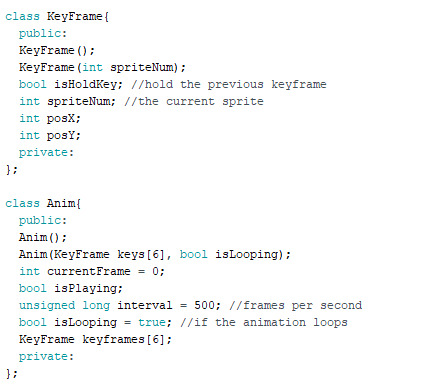
class KeyFrame{ public: KeyFrame(); KeyFrame(int spriteNum); bool isHoldKey; //hold the previous keyframe int spriteNum; //the current sprite int posX; int posY; private: };
class Anim{ public: Anim(); Anim(KeyFrame keys[6], bool isLooping); int currentFrame = 0; bool isPlaying; unsigned long interval = 500; //frames per second bool isLooping = true; //if the animation loops KeyFrame keyframes[6]; private: };
class ScreenState{ public: ScreenState(); ScreenState(String text, Anim animation); bool isPlaying; String text; Anim anim; private: };
#endif
ScreenSet.cpp
#include "Arduino.h"
#include "ScreenSet.h"
KeyFrame::KeyFrame(){} KeyFrame::KeyFrame(int spriteNum){ this->spriteNum = spriteNum; } Anim::Anim(){} Anim::Anim(KeyFrame keys[6], bool isLooping){ for(int i = 0; i < 6; i++){ this->keyframes[i] = keys[i]; } this->isLooping = isLooping; } ScreenState::ScreenState(){} ScreenState::ScreenState(String text, Anim animation){ this->text = text; this->anim = animation; }
0 notes
Text
Working Clock
In order to make the clock work, I needed to use the calculation referenced in this post. I used the example for interrupting a rotation with code as seen in this example of the TinyStepper library where a while loop is used within the main loop() function to keep code running as expected while the rotation happens. I then set the speed and acceleration to 0.0021 as a 21000th of a second and moved the stepper 1 step per 21 seconds effectively.
I ran into some issues throughout the process as I could not decide whether to count with millis() or use the while loop with interrupts. I was trying to do both at once, setting the rotation initially and then starting the rotation at every interval of 21 seconds with 1 on acceleration, speed and steps. I could not get this to work with the processMovement() function so opted for the while loop interrupt instead.
The crux of this code that hasn't been explained previously is that instead of setting the acceleration, speed and then moving into the rotation, this code opts to setup the rotation's parameters first, adding a reference position at each turn, almost like resetting a set of scales to 0, to get the start coordinate of the rotation to be used for any movements that use TinyStepper's relative movement functions (which set up coordinates based on how many steps have been moved from the origin point). It then executes the rotation with processMovement().
Videos are available here: https://photos.app.goo.gl/G6DV6qYz4QDSWrxb9

The code is below:
#include
unsigned long currentTime; unsigned long prevTime; int interval = 21000; //in ms const int STOP_BUTTON_PIN = 9; const int MOTOR_IN1_PIN = A2; const int MOTOR_IN2_PIN = A3; const int MOTOR_IN3_PIN = A4; const int MOTOR_IN4_PIN = A5; //const int STEPS_PER_REVOLUTION = 2048; TinyStepper_28BYJ_48 stepper;
bool stopFlag = false; bool hasPrinted = false; bool hasSet = false; void setup() { pinMode(STOP_BUTTON_PIN, INPUT_PULLUP); stepper.connectToPins(MOTOR_IN1_PIN, MOTOR_IN2_PIN, MOTOR_IN3_PIN, MOTOR_IN4_PIN); Serial.begin(9600); }
void loop() { stepper.setSpeedInStepsPerSecond(0.0021); stepper.setAccelerationInStepsPerSecondPerSecond(0.0021); stepper.setCurrentPositionInSteps(0); stepper.setupMoveInSteps(1); stepper.processMovement(); currentTime = millis(); while(!stepper.motionComplete()) { stepper.processMovement(); if(!hasPrinted){ Serial.println("isMoving"); hasPrinted = true; } } Serial.println("finishedLoop………………………….."); hasPrinted = false; }
0 notes
Text
Rotation based on time
In order to rotate the clock in real time, I needed to do some math! I needed to complete a rotation per every 12 hours. We cannot use delays as we need to use a while loop to run an almost separate 'update' function while the stepper's motion is incomplete as detailed in the official example.
The stepper motor gets quite hot under constant power so this will wear out over time unfortunately.
The complete rotation of the stepper motor in steps in this case is 2048. To get the speed of rotation, we need to divide this down to get a steps per second value.
I used a tutorial as referenced in this post to count the milliseconds between actions without delays. After asking my tutor for help, we discussed that the easiest way to calculate this is 12 (the hours) x 60 (the mins in an hour) x 60(the second) / 2048. We found that it divides to 21.09375 which we rounded to 21. So we need to perform 1 step every 21 seconds.
0 notes
Text
Counting Time
Time is a major issue in my game as I need the clock to work as well as animations on the LCD. I used a tutorial to get the accurate time for animations and the clock.
It used the millis() function which returns an integer value of the milliseconds passed since the program started. I then work out the difference between this and another integer called prevTime which gets stored every time the difference between the currentTime and itself are larger or equal to the interval. For this experiment, I set the interval to 1 second, or 1000 milliseconds. I used the serial monitor to monitor the time as shown in the video below.
The types are unsigned longs which are 32 bit variables for very long integer values up to 4,294,967,295.
Here is the code:
unsigned long currentTime; unsigned long prevTime; unsigned long interval = 1000; bool hasRun;
void setup() { Serial.begin(9600); }
void loop() { currentTime = millis(); if(currentTime - prevTime >= interval){ Serial.println("a second"); prevTime = currentTime; } }
0 notes
Text
Testing Construction, Errors
While testing, I found that the stepper motor would vibrate out of position due to its gears, so I seated it in a divot in the cardboard base by cutting a hole and sandwiching it.

This fixed the issue well.
Here is a video demonstrating a basic example from the TinyStepper_28BYJ_48 library to see it in motion:
0 notes
Text
Construction of the Spinner for Testing
Before I embarked on creating a time based stepper or servo, I decided it would be best to create the actual paper pieces of the calendar device so I could more accurately see how much I needed it to spin per second to complete a full day.
There are a lot of images here so beware clicking below as it may clog your feed!
First, I cut the circles, tracing an old portable charger.

I didn't have a hole punch so I poked holes with a knife for the pivot

I drew on the clock face and basic fake tasks

I made a small cardboard pole for the 'masking' paper to sit on so it did not rotate, attached with a bulldog clip

I then hot glued this onto a cardboard base

I also added cardboard stoppers to sandwich the moving piece of paper so it was stable and flat

And laid the stepper motor below the 'masking' paper

And the basic construction was complete, ready to test with time scale based rotation and task detection.
0 notes
Text
Stepper Motor On Tasks
While not entirely necessary for this project, to better understand the functionality of the stepper motor, I played around with getting it to stop when a task was detected and restart when the paper was detected again. I however realised that the rest of the program would not run whilst the stepper motor was completing its rotation. In order to stop it mid rotation, I needed to find an alternative. I then opted for a poor fix, which was to rotate 1 step every frame. Due to the speed needed for this and the on and off of the motor, it ran extremely hot and revved quite a bit. I will be exploring further methods using the documentation for the TinyStepper functionality to get a better fix.
The way this could be used well in the final project would be to detect an alignment arrow to calibrate the stepper motor to the correct time needed for the clock/spinner.
I unfortunately do not have a video for this at this time but will record one and add it when I can. The code is below:
include
// // pin assignments, any digital pins can be used // const int LED_PIN = 3; const int MOTOR_IN1_PIN = 11; const int MOTOR_IN2_PIN = 10; const int MOTOR_IN3_PIN = 6; const int MOTOR_IN4_PIN = 5;
const int LDRPIN = A0;
const int STEPS_PER_REVOLUTION = 2048;
// // create the stepper motor object // TinyStepper_28BYJ_48 stepper;
int light; int neutral; int dark; int bright;
void setup(){ // // setup the LED pin and enable print statements // pinMode(LED_PIN, OUTPUT); Serial.begin(9600);
digitalWrite(LED_PIN, HIGH); pinMode(LDRPIN,INPUT); // // connect and configure the stepper motor to its IO pins // stepper.connectToPins(MOTOR_IN1_PIN, MOTOR_IN2_PIN, MOTOR_IN3_PIN, MOTOR_IN4_PIN);
stepper. stepper.setSpeedInStepsPerSecond(256 * 16); stepper.setAccelerationInStepsPerSecondPerSecond(512 * 16); } bool isNeutralSet; bool temp = false; int steps = 10;
void loop(){ if(!isNeutralSet){ delay(100); neutral = analogRead(LDRPIN); Serial.print("neutral value: "); Serial.println(neutral); isNeutralSet = true; }
stepper.moveRelativeInSteps(steps); light = analogRead(LDRPIN); delay(100); Serial.println(light); if(light < neutral - 6 && !temp){ Serial.print("task detected \n"); steps = 0; temp = true; } else if(light >= neutral && temp){ Serial.print("task ended or no task \n"); steps = 10; temp = false; } /* // // Note: This example uses "relative" motions. This means that each // command will move the number of steps given, starting from it's // current position. //
// // set the speed and acceleration rates for the stepper motor // stepper.setSpeedInStepsPerSecond(256); stepper.setAccelerationInStepsPerSecondPerSecond(512);
// // Rotate the motor in the forward direction one revolution (2048 steps). // This function call will not return until the motion is complete. // stepper.moveRelativeInSteps(2048);
// // now that the rotation has finished, delay 1 second before starting // the next move // delay(1000);
// // rotate backward 1 rotation, then wait 1 second // stepper.moveRelativeInSteps(-2048); delay(1000);
// // This time speedup the motor, turning 5 revolutions. Note if you // tell a stepper motor to go faster than it can, it just stops. // stepper.setSpeedInStepsPerSecond(500); stepper.setAccelerationInStepsPerSecondPerSecond(1000); stepper.moveRelativeInSteps(2048 * 5); delay(2000);*/ }
0 notes
Text
LCD Custom Sprites
After reading and understanding further into the programming side of the LCD tutorial, I decided to create a custom sprite that reacted to a button. Initially, I simply put a sprite below the first text print by moving the cursor to the specified zone (line 2, zone 4). I then created my sprite, using, from the tutorial, a binary array based on the resolution of each square in the display. We simply use the binary 1s and 0s to tell it which dots to light white and which to keep the same as the background. This means it works very similarly to pixel art which was easy to adapt to. I initialised the custom sprite as a character in setup using the createChar function. I then referenced this to print it.
Code below:
/*
Arduino LCD Tutorial Modified by Casper Witor with custom sprites, but originally Crated by Dejan Nedelkovski, www.HowToMechatronics.com * */
include // includes the LiquidCrystal Library
byte hamster[8] = { // Array of bytes B10001, // B stands for binary formatter and the five numbers are the pixels B11111, B10101, B11011, B11111, B11011, B10101, B11111 };
byte sleepHam[8] = { // Array of bytes B00000, // B stands for binary formatter and the five numbers are the pixels B11111, B00100, B11011, B11111, B11011, B10101, B11111 };
const int buttonPin = 11; int buttonState = 0; int currentSprite = 0; bool isSet; bool isToggled = false;
LiquidCrystal lcd(1, 2, 4, 5, 6, 7); // Creates an LCD object. Parameters: (rs, enable, d4, d5, d6, d7)
void setup() { pinMode(buttonPin, INPUT); lcd.begin(16,2); // Initializes the interface to the LCD screen, and specifies the dimensions (width and height) of the display } lcd.createChar(0, hamster); //creates a custom character lcd.createChar(1, sleepHam); //creates a custom character lcd.clear(); }
void loop() { buttonState = digitalRead(buttonPin); if(buttonState == HIGH){ currentSprite = 0; isSet = true; } else if(buttonState == LOW ){ currentSprite = 1; isToggled = false; isSet = false; } lcd.print("Hello"); // Prints "Arduino" on the LCD lcd.setCursor(2,1); // Sets the location at which subsequent text written to the LCD will be displayed lcd.write(byte(currentSprite)); lcd.noCursor(); // Hides the LCD cursor delay(100);
lcd.clear(); // Clears the LCD screen }
0 notes