
Don't wanna be here? Send us removal request.
Statistics
We looked inside some of the posts by logicalsol-blog and here's what we found interesting.
Average Info
Notes Per Post
0
Likes Per Post
0
Reblog Per Post
0
Reply Per Post
0
Time Between Posts
27 days
Number of Posts By Type
Photo
4
Text
6
Last Seen Tumblr Blogs


Fun Fact
Tumblr was acquired by Yahoo for $1.1B in 2013.


Photo

SOLIDWORKS 2019 launch event https://www.instagram.com/p/Bpqybg7HTRs/?utm_source=ig_tumblr_share&igshid=mycqv37c0dze
0 notes
Photo

Dussehra Celebrations @logicalsol https://www.instagram.com/p/BpqyAqmnb09/?utm_source=ig_tumblr_share&igshid=t6qaxyv92r8r
0 notes
Text
Managing Wires in SolidWorks Electrical
SOLIDWORKS Electrical can manage wires in three following ways 1.Global Wire Mark Display: Now we can select between Wires and Equipotential depending upon the numbering style directly from Configurations. Go to Project Tab -> Drop Down Configurations and select Wire Style manager as shown below.
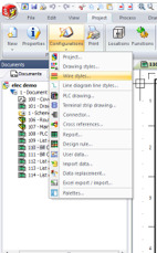
From here we can change the options from marks to labels or from labels to marks

2.Handling Unused Wires: The main purpose of this option is how to use unused wires in a project by assigning them to already assigned wires in a drawing Go to Project Configurations -> Formula Manager Mark Option

3.Wire Numbering Group: In the Wire Style Manager, the group properties are accessible through the contextual menu of the group. You can also select the group and click on Properties icon. Wires are grouped within a numbering group so that all wires that are part of the group use the same counter. This ensures numbering continuity in the wires, even if they are different wire types.SOLIDWORKS Authorized Reseller in Hyderabad To get more updates on SOLIDWORKS Follow Us on LinkedIn: Click Here
For more details Like Us on Facebook: Click Here
For videos SUBSCRIBE to our channel: Click Here
For more information: Click Here Phone : 9133445956
0 notes
Text
Speed your design process with intuitive SOLIDWORKS software

What is CAD? CAD stands for computer-aided design and is the use of computer systems to assist in the creation, analysis, modification, and optimization of the design. Generally, CAD is a much quicker tool than traditional methods of design and can improve the quality and productivity of a project. It is used in many industries and can be used for 2D and 3D design. Designers using 3D CAD can enjoy using a seamless and intuitive design environment to express and realize their ideas. SOLIDWORKS is a solid modeler and utilizes a parametric feature-based approach to create models and assemblies, capturing the design intent of the creator of the part being worked on. SOLIDWORKS offers product solutions available for • SOLIDWORKS 3D CAD • SOLIDWORKS Simulation • SOLIDWORKS Product Data Management • SOLIDWORKS Technical Communication • SOLIDWORKS Electrical Design • SOLIDWORKS PCB • SOLIDWORKS CAM Each of the products and those solutions are either modular add-on’s to SOLIDWORKS or separate products in of themselves. SOLIDWORKS 3D CAD solution eliminates the design constraints faced by any designer during real-time performance. Design iterations take up to 60% of a designer’s time due to the dynamic nature of the work. And any 2D tool is incapable of handling changes that crop up anytime during a project, without consuming excess time. SOLIDWORKS’ intuitive interface and design capabilities address these problems efficiently. SOLIDWORKS Simulation suite allows you evaluate performance, improve quality and increase product innovation. Establish real-world scenarios to test products prior to manufacturing for a wide range of parameters such as durability, static and dynamic response, the motion of assembly, heat transfer, fluid dynamics, and plastic injection. SOLIDWORKS product data management (PDM) solutions help you get your design data under control and substantially improve the way your teams manage and collaborate on product development. SOLIDWORKS Technical Communication: Repurpose existing 3D design data to create high-quality graphical assets for product deliverables, including technical illustrations, animations & interactive 3D experience. SOLIDWORKS Electrical CAD greatly simplifies 2D electrical schematic and PCB creation by providing an intuitive interface that gives you faster results. Bi-directional integration in real time with SOLIDWORKS 3D CAD provides better collaboration and productivity, resulting in fewer product delays, more consistent and standardized designs. SOLIDWORKS PCB is powered by Altium and provides the best in PCB Electronics design technology. Capable of meeting the demands of today's increasingly complex designs, this solution is packed with the latest features from schematic to board layout, to keep you at your most productive. SOLIDWORKS CAM is a fully integrated service of design and manufacturing processes under only one system. Through the use of Knowledge-Based Machining, all machining processes can be automated, increasing your productivity. For more details visit our site: http://www.logicalsolutions.in/ For more Subscribe us: https://www.youtube.com/channel/UCUy8L13drqfG4T8-LxMtkiQ Call for further assistance: 9133445956
0 notes
Text
Search Tools in SOLIDWORKS Electrical : SOLIDWORKS Authorized Reseller Hyderabad
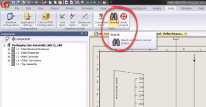
Inside of SOLIDWORKS Electrical, there are two powerful search tools that are great for navigating through the software enabling you to quickly find what you need when you need it. SOLIDWORKS Electrical Schematic design capabilities simplify development of electrical systems with robust and intuitive single-line and multi-line schematic tools for planning your electrical system. SOLIDWORKS Electrical has a database with over half a million manufactured parts for use in your design. With just a simple drag and drop these components can be added to your schematic sheets in no time at all. But as you start adding more and more components to more and more sheets, powerful search tools become vital. Here’s how to use them. The first search tool can be found under the “Tools Ribbon” on the Command Manager at the top of the screen.SOLIDWORKS Authorized Reseller in Hyderabad
This tool is a great way to find components in the project based on properties such as their mark. Just type in the mark and it will search all instances of the mark throughout the project. Clicking on the component will give you a preview of it in the sheet.
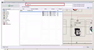
After finding the component, you can navigate to it in the project by right-clicking on the component and selecting “go to browser”. This is where you can make changes to its properties. You do this through the component browser on the left side of the screen. You can also choose the option for “go to drawing” which will take you directly to the component on the drawing.


Now with both of these search tools in your toolbox, navigating through SOLIDWORKS Electrical you are able to quickly find what you need when you need it.SOLIDWORKS Authorized Reseller For more details visit: http://www.logicalsolutions.in/products http://www.logicalsolutions.in/services For training visit: http://www.logicalsolutions.in/training For more Videos: https://www.youtube.com/channel/UCUy8L13drqfG4T8-LxMtkiQ/videos Contact: 9133445956
0 notes
Text
What’s New in SOLIDWORKS 3D Interconnect 2018
SOLIDWORKS 3D Interconnect is a new feature introduced in SOLIDWORKS 2017, capable of working seamlessly with 3rd party CAD files from various CAD tools and unlocking new workflows to streamline collaboration with customers and vendors. SOLIDWORKS 3D Interconnect bypasses the entire translation process of 3rd party CAD files and allows us to work as they were native SOLIDWORKS files. With SOLIDWORKS 3D Interconnect, we can have direct integration of CAD files from various design tools like PTC®, Creo®, Autodesk® Inventor®, Siemens® NX, SolidEdge®, and CATIA®.
In SOLIDWORKS 2018, this tool has been developed even more better.
The first thing you’ll notice is support for neutral file formats; these include STEP, IGES, ACIS, and JT. These files no longer need to be translated, and instead, can be simply inserted into your SOLIDWORKS assemblies and used like other components. This works the same way native 3rd party files can with 3D Interconnect. These neutral files will recognize when the files are changed or replaced. And like native 3rd party files, they can be easily updated without the need for deleting and re-importing the files. However, neutral files do not support the same intelligent Face ID mapping that native 3rd party files do.

Other new enhancements take your legacy 3D files further, including support for reference geometry such as sketches and reference planes. Allowing you to do more with your existing files from other 3D design tools. Eliminating the need for time-consuming migration of data.

Finally, Custom Properties are now supported for your legacy 3D files. Either opening a 3rd party file or inserting it directly into an assembly. This means Bills of Materials and Drawings can now automatically read and populate themselves using the information previously defined in their native design tool.

0 notes
Text
What’s NEW in ASSEMBLY in SOLIDWORKS 2018 | SOLIDWORKS Authorized Reseller in Hyderabad
Just like in SKETCH, SOLIDWORKS 2018 builds on existing assembly delighters, providing new enhancements that focus on increasing productivity. In today’s global marketplace, great products need to get built faster than ever. SOLIDWORKS 2018 introduces enhancements that help you deliver assembly designs in less time and effort.


After choosing the number of instances you can simply select a rotation reference and specify the incremental angle. This speed up the creation of all kinds of innovative designs and removes the needs for additional features.Adding mates between hidden surfaces can be challenging. SOLIDWORKS 2018 speeds up the process by allowing you to temporarily hide surfaces whilst in themate commands by pressing the ‘ALT’ key. You can now select the hidden faces and get your parts in place fast.
When working with components of different units or even imported parts, it is common where the certain holes do not align properly. Now, in SOLIDWORKS 2018 you can create MISALIGNED mates’. This allows two Concentric Mates to be solved correctly, by maintaining the concentricity of either Mate – or… by shifting the component symmetrically between the two. The Feature Manager displays useful information about the misalignment and they also show up clearly in the Mates folder too. This new capability removes the need to make slight changes to legacy components that may be used in many assemblies.

Creating Exploded Views is a great way to understand and communicate your designs in SOLIDWORKS. Now, with SOLIDWORKS 2018 you can now quickly and easily create automatic explode lines using the Smart Explode Line tool. SOLIDWORKS automatically gathers all the components in the exploded view and previews each explode line. The explode line for each component defaults to the Bounding Box, but you can easily choose the Origin or even drag to any other point. SOLIDWORKS also allows you to apply this to every other identical instance – saving a lot of time and effort. As you would expect, modifying the Exploded View updates the Explode Lines instantly – keeping everything accurate and up to date. SOLIDWORKS Authorized Reseller in Hyderabad

These are the assembly enhancements in SOLIDWORKS 2018 that improve your day to day productivity to get your products built faster. For More Details Visit : http://www.logicalsolutions.in/ Phone : 9133445956
0 notes
Text
SOLIDWORKS Reseller Hyderabad | Logical Solutions Ltd

Established in 2000 and supporting more than over 200+ Customer’s, Logical Solutions is proud to be the leading SOLIDWORKS reseller in Hyderabad, Telangana & A.P. We’re passionate about connecting customers with leading design and manufacturing technology to unleash your imagination and ingenuity. We provide solutions to our customers to work better, faster and smarter than even never before. When Customer’s deals with Logical Solutions Ltd, will soon find us we are very responsive. We have a very personal approach and work to become a natural extension of there business. Whatever stage Customers are, we are confident we can help, whether you are new to 3D design, making the transition from 2D, moving from older 3D systems or you’re an expert needing additional support – we have all the experience, expertise on SOLIDWORKS Suit of products. Our sales and support team cover all the Telangana & AP Industrial Sectors. We support the full line of SOLIDWORKS solutions including SOLIDWORKS, SOLIDWORKS Simulation, Enterprise PDM, Sustainability, SOLIDWORKS Composer and Draft-sight 2D Design. Our advanced solutions are designed to complement your existing workflow to save you time and money in your design process. We’re happy to be the partner with Inspection expert for inspection report automation and ballooning software, SIMPOE to simulate the plastic injection manufacturing process. Logical Solutions Ltd boast the largest and most knowledgeable engineering team in Telangana & A.P, providing world-class technical support, robust training, consulting and implementation services to our clients. We are dedicated to helping our clients succeed. We help Our Customers to increase productivity, enhance performance, and outsmart the competition. SOLIDWORKS Authorized Reseller in Hyderabad For More Details Visit: http://www.logicalsolutions.in/ Phone: 9133445956
0 notes