
Statistics
We looked inside some of the posts by moonflowercarnivore-blog and here's what we found interesting.
Average Info
Notes Per Post
0
Likes Per Post
0
Reblog Per Post
0
Reply Per Post
0
Time Between Posts
23 days
Number of Posts By Type
Text
7
Last Seen Tumblr Blogs


Fun Fact
Celebrities use Tumblr as well.
Text
Particle ring with variable width
youtube
Like the spiral trails effect which was inspired by Atlus’ games, this 3D ring with variable width is inspired by Atlus’ latest hit Persona 5 which is used in magic effects like “Charge”, “Concentrate”, etc. The idea is very simple and feasible in Unity particle system. Better still no scripting or shader coding is needed. This requires Unity 5.2 at least which has begun to support texture sheet animation module for mesh particle.
(0:54) You need a custom-built mesh. I do it in Blender because it is free and simple, but the procedure should be interchangeable with other mainstream 3D graphic editors.
Add a “mesh”-”circle” with “triangle fan” fill type. You can use higher or lower vertices depending how much you weight between resolution and performance, but 32 vertices is very generously already.
Press “Tab” to enter mesh edit mode.
Press “A” to select all vertices/edges/faces if nothing is selected.
Press “U” and choose “reset” so all triangles use the same simple UV mapping. (Actually this step is optional depending on which version of Blender you are using, just better safe than sorry.)
Create a separate view for “UV/Image Editor”.
Click the plus sign to add a new UV image. Change width and height to 256 px and generated type to “color grid”.
Optionally change the “viewport shading” in 3D view to “texture” for inspecting UV mapping on the mesh.
Select vertices of each point of all triangles and change their position as shown in the video from 2:28. B1-B2 side should align with the circumference of the ring mesh. The vertex at the ring center only needs to touch the bottom edge of the UV map. Its x-axis position is irrelevant. This all will make sense once we assemble the effect in Unity.
Change the mesh name in “object” property so it is not the default “circle” to avoid confusion. For example, “ring variable”.
Save the Blend file outside of Unity “Assets” folder and export FBX file inside “Assets” folder.
Normally in Blender I would rotate the x-axis of the mesh by -90 degree and apply transform change before exporting FBX for Unity, but for this mesh because it will be treated as quad in Unity, I leave its rotation in Blender intact. In Unity 2017 where you can set mesh particle to always face the view, the default rotation in Blender allows the circle mesh to face the view correctly in Unity.
(4:11) The texture for this mesh uses a 2:1 rectangular canvas instead of square for higher width resolution. The texture is an isosceles triangle, the odd point is at (0, 50%) and the other two are (100%, 0) and (100%, 100%) respectively. You can add outer glow if you like but it need cleanup to avoid the glow clipped by the edges. If the new texture has black background as shown and is only intended for Additive shader, change “alpha source” to “none”. Otherwise, the texture should have transparent background, retain “input texture alpha” and enable “alpha is transparency” for shaders like Alpha Blended. Change “wrap mode” to “clamp”. Create a new material, select the desired particle shader, load the texture.
To make the new ring mesh size consistent to the built-in sphere and cube meshes, in mesh property I change the “scale factor” to 100, remove “import materials” and apply.
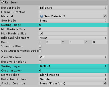
(5:33) Finally time to assemble the effect. In the renderer module, change “render mode” to “mesh” and load the ring mesh. Enable “texture sheet animation”. For demonstration purpose, I set the x tile division to 16 by now. Drag the value of “frame over time” and you can already see the effect. At maximum value, the whole circle is completely filled, because the particle picks the rightmost column of the texture; conversely at smaller value, the width of the ring texture shrinks as the column moves leftward. Using this behavior you can draw curve to animate the ring width. Now the whole ring looks zigzag instead of smooth. This can be improved by increasing the x tile division, maybe 512. At 1024, the zigzag glitch is nearly invisible. Use 2048 if you are very insecure.
Extra tip: In Blender you can move the ring center to one side of the ring circumference. Change the mesh name and export a separate FBX file to Unity Assets folder. Remember to change the mesh scale factor in Unity and load this mesh in particle system originally using another ring mesh. It will create a crescent instead of concentric ring. This is quite reminiscent of the old-school anime fireball.
0 notes
Text
Rotary charging trails
youtube
Thanks to the Trails module of Shuriken Particle System introduced to Unity 5.5 onward, we can make the rotary charging trails as seen in the magic effect "Megido" in Shin Megami Tensei: Nocturne and Digital Devil Saga with ease. Although having said that, the rotary part needs a bit of help from other component. The effect in this video is included in our free asset Particle Attractor on Asset Store.
Basic concept first before applying rotation. To make a bunch of particles emitted from an imaginary sphere surface towards the centre, you choose the "sphere" emitter shape and enable "emit from shell", change the start speed to negative value. That is it. If you want the particles exactly die at the centre instead of continuing the movement beyond the centre, it is simply that the radius of the sphere emitter equals start speed times start lifetime. For example, 2 second start lifetime, -2.5 unit/second start speed and 5 unit sphere radius. You may wonder if you can control the speed over lifetime so each particle can stop moving at like 80% lifetime, we made a suggestion to Unity technicians. This is available for testing in temporary build and is expected to be implemented in 5.7, so be patient.
Obviously you need to enable Trails module so a trail is generated from each particle. Make sure "world space" for trails (not the particle system) is enabled. To make the trail fades at the end of the tail, change the value type of "color over trail" to "gradient", modify the alpha gradient so it is 0 alpha at the 100% location. Lastly assign a material for trails in Renderer module. It can use any Particles shader even without loading any texture, we usually just use Mobile/Particles/Additive.
Now to make the particles revolving around the source object centre, we have two options: One, we create an animator and looping animation which increments y-axis rotation of object transform from 0 to 360. This is a bit less flexible if you want to change the rotating speed midway. Two, we write a very simple script which does the exact same job as the animation. The script is available in Particle Attractor for free download. You attach the script on the game object and type a value to either axis you want to rotate, but most likely you should avoid rotating x axis which gives you jittery trails, does not look totally terrible if you want this specific effect. Either way, you need to make sure the "simulation space" of the particle system (in Main module) to be "local", otherwise in "world space" the particles will just ignore the updated transform of the source object after emission.
For glowing effect, some may use thick trails and texture with vertical gradient. We still recommend to use smaller width of the trails because if it is wider, the ugly banding of the trail will become very visible. Then apply post-processing effect Bloom instead. If you want to achieve selective Bloom, enable HDR options in the camera and the Bloom components, set the bloom threshold equal or greater than 1, so only pixel with RGBA values greater than 1 is bloomed. To make the trails more likely to bloom, the trail material should use any shader which supports amplified color emission like the Standard Shader, or a dedicated Standard Particle Shader which is currently available for testing (requires Unity 5.6.0f2 at least).
0 notes
Text
Rigid Body and Particle System
youtube
From Unity 5.5 onward, particle system (PS) that uses emission rate over distance or inherit velocity (both heavily used in our particle effect assets) and is parented to a rigidbody (RB) object will appear not functional when you drag the object (with RB component) or change the position values in transform component.
The reason is that RB velocity has overriden any form of position translation to feed the velocity values to PS modules which require velocity data to work properly. Simply put, you should use Rigidbody.velocity (not even Rigidbody.position which is for detecting boundary) instead of Transform.position/Translate to move the object. If you really need to directly modify the position without velocity, before doing so, enable "is kinematic" temporarily, effectively disabling RB physics. Another apparent option is to switch from RB to Character Controller if applicable.
If you insist on RB while the PS effect still acts strange because of RB physics, you need to update the Rigidbody.velocity of your parent object which receives movement with the resultant movement value. In the official Tanks tutorial which has not been updated to Unity 5.5 for fixing the dust trail from the tank wheels, this would mean adding the following line below line 125 of TankMovement.cs (_Completed-Assets):
m_Rigidbody.velocity = transform.forward * m_MovementInputValue * m_Speed;
Lastly if the particles emitted which are supposed to form a connected line but appear broken when physics is applied, you can enable RB's interpolation which also prevents the movement of the object appears jittery.
Because physics engine does not take place when the scene is not played, it would appear our particle effects malfunction under the aforementioned circumstance. Unity technicians have considered to disable RB component or similar thing when the scene is not played for properly previewing the particle system.
0 notes
Text
[Tutorial] Unity Shader Basics
VERSION 1
For artists and programmers, at the beginning when you are involved in game projects, shader looks like something you don't have to worry about. But indeed, shader is about everything you see on the screen... if you don't understand it, it causes performance issues to your game, and definitely limiting your creativity. If you know it well, shaders can save memory, also save up lots of time and work from both artists and programmers, even let you create something that you've never thought of!
This tutorial is good for both artists and programmers for understanding what shader is, what it actually does in Unity, and how to write shader. This tutorial will only provide you the basic concept. Once you understand the basics, you can always move forward easily.
Try to read from the beginning. Artists, you can skip the parts that contain programming. I've tried my best putting concepts in picture-form...
Topics to cover :
:: Rendering Pipeline - Rendering an Object ::
3D? 2D? UI? Particle System? They are all 3D!
So how the objects are rendered and displayed onto the screen?
Material you know is a ball, but what is shader?
Then what's happening in Shader?
:: Render Queue - Rendering Order of Objects ::
The normal order of things
Then what is AlphaTest / Cutout and Transparent? What’s so special?
Transparent (ZWrite Off) VS Transparent Cutout (ZWrite On)
:: The Sorting System in Unity ::
The Systems
Batching the Draw Calls
:: Shaders in Unity ::
Types of Shaders
Unlit and Surface Shader, the Basic Structure
Unlit Shader
Surface Shader
Transparent
Blending
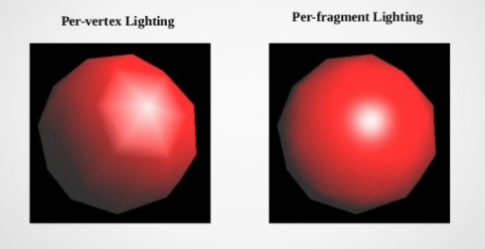
Lighting
Multi-platform Shader?
:: Tips / Optimization for Shader ::
Apply Texture Tiles and Offset
Per-Vertex data VS Per-Material Properties
Put calculation in vert() or frag()?
SubShaders and Fallback
Use Cheaper Data Types
Use the standard library / use the provided API
CPU VS GPU
Shader model
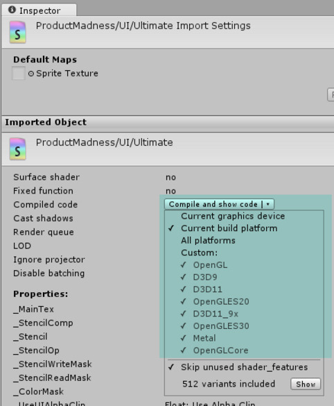
Settings in Editor VS Shader Support
Shader Feature and Multi-compile
Cheaper Shader Options
More Inspirations
Useful Links
:: Rendering Pipeline - Rendering a Pixel of an Object ::
3D? 2D? UI? Particle System? They are all 3D!
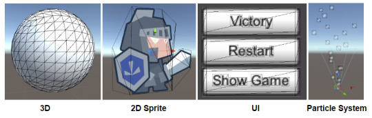
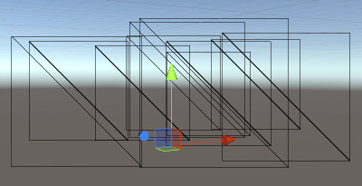
If you turn on wireframe in Unity, you will see actually everything is 3D; they all have vertices, polygons / triangles, UV coordinates, textures...bla bla bla
That means, everything follows the same basic rendering pipeline...
So how the objects are rendered and displayed onto the screen?
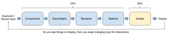
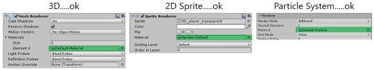
If you use Unity you will be familiar with the flow, which is you have components attached on GameObjects doing the logics of the game, and on the GameObjects which is a 3D character or UI or Sprite or stuffs that will appear on your monitor, you can always find a Renderer component on it.
Skinned Mesh Renderer, Mesh Renderer, Sprite Renderer, Particle System Renderer...bla bla bla again, there is always a Material assigned on it.
But you say : Hey! The Material slot on uGUI is empty!
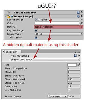
The concept now is :
Everthing is 3D. Every object you see in the game has a Renderer. Every renderer has a Material (s). Every material is using a Shader.
Material you know is a ball, but what is shader?
Material is the ingredient basket. Shader is the recipe.
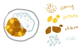
Imagine you have a recipe (Shader) teaching you what you need and the steps to cook Curry Chicken Rice, Material is listing out how many curry, how many potatoes, how many chicken and how many rice you are going to put into cooking...
(Then finally you see different yellow colors on your monitor XD)
So, even you do not put any chicken, your dish is still called Curry Chicken Rice! The cooking steps are not skipped, You just pour 0 chicken onto your pan!
Shader is a piece of codes running inside GPU, describing how an object is rendered.
Then what's happening in Shader?
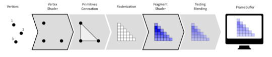
[Image Source] Each vertex carries their own data : position, normal, color....etc
↓
Each vertex will go through Vertex Shader
↓
Vertex shader grabs the input vertex data, do calculations then output the processed vertex data and some more other data for later use
↓
Vertex will link together to form triangles
↓
Triangles will become fragments (will be called pixel when it is shown on your monitor)
↓
Each fragment will go through Fragment Shader
↓
Fragment shader grabs the output from vertex shader as input, do calculations then output a color, or a set of colors => the color of that object in that pixel!
↓
The output color will blend with other color from other objects
↓
They will be stored in Frame Buffer, queuing up to be shown on your monitor~! [Image Source] Feels like drawing this and then color it...
So this is how 1 object get to displayed on your monitor.
Then what’s happened to many objects? Which pixel color will be used?! You don’t want to waste time calculating the colors that will not be seen on the monitor, right?
:: Render Queue - Rendering Order of Objects ::
The normal order of things
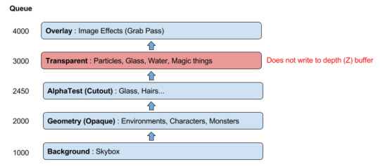
[Information Source]
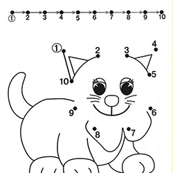
Don’t worry if you couldn’t understand the chart above. Just think about how an artist draw an illustration (in a very routine way).
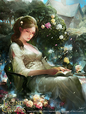
[Image Source] Background is always at the back, so draw the house first. (Background)
↓
Then start painting up some trees, props, and also character! (Geometry)
↓
Then add some fancy magic smokes as well as the flying flower petals. (Transparent)
↓
Finally adjust the whole image brightness, contrast, apply sharpening / blur..etc (Image Effects)
Now scroll up back to the chart. Understand now?
The render queue numbers are just relative numbers, indicating which thing on the illustration to draw first. But
Render queue doesn't actually change what items are drawn on top of others, it simply changes in what order they're rendered.
[Information Source]
So this is why the dress is a little bit transparent, and some effects are being covered by character and some are covering the character and so on.
Then what is AlphaTest / Cutout and Transparent? What’s so special?
Depth (Z) Buffer for Opaque Objects
Objects that write into Depth (Z) Buffer will let the “Z” position (depth) of fragment to determine which is drawn on top of another.
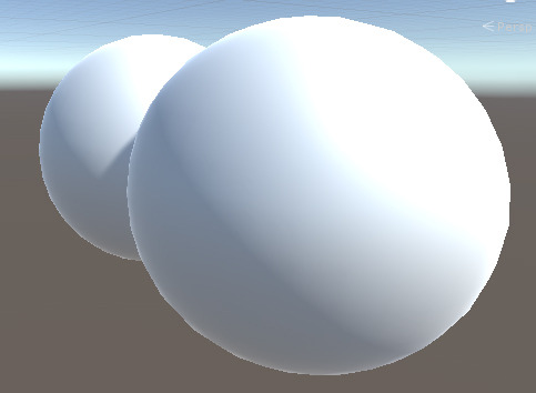
i.e. You will not see the part of the object that is being covered because the sphere in front is closer to camera. And the part that is being covered is actually being discarded.
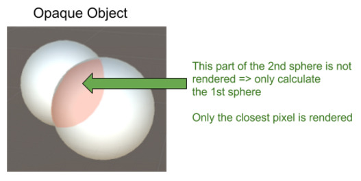
So artists (GPU) don’t have to draw the part of the house that is covered by the dress or other objects. So that you save up some drawing time.
Transparent Objects WITHOUT Depth (Z) Buffer
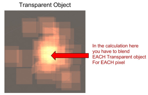
So color1 has to blend with color2, then blend with color3...color4...color5........You can imagine there is so much workload to calculate the final color!
Because all colors from all objects has to be taken into account, transparent objects will not write into Depth (Z) Buffer.
---> OVERDRAW PROBLEM <---
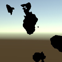
Objects that has 100% transparency would still cause overdraw problem.
Also, it looks invisible but vertices are still there...
Objects that looks opaque but you use a transparent material on it, it is an transparent object with 0 transparency! i.e. overdraw problem
Alpha Test (Transparent Cutout)
Alpha Test, also we call it transparent cutout, is a "transparent" shader discarding all the fragments which the fragment alpha does't pass the threshold.
So the remaininig fragment are all with alpha = 1. Thus, it can be written into Depth (Z) Buffer, so that we can skip all the colors covered by it.
Does not like opaque objects, in shaders using fragment discard, all fragments are processed before discarding => still consume some processing power in calculating the pixels that are not being rendered...
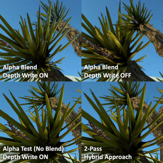
Transparent (ZWrite Off) VS Transparent Cutout (ZWrite On)
[Image Source]
Because transparent does not write into Depth (Z) Buffer, when it is used on a tree with lots of leaves which the z position cannot tell the correct sorting order of different parts of the tree(s), the sorting problem happens. (TOP RIGHT)
In order to fix the sorting problem, you can turn on ZWrite, but you will see the skybox in those 100% transparent areas...(TOP LEFT)
But if you use Transparent Cutout, the border of the leaves are not smooth anymore, all transparent / semi-transparent pixels are gone. (BOTTOM LEFT)
Finally, to have both correct sorting and smooth border, is to "render" the tree twice : 1. Transparent 2. Transparent Cutout (BOTTOM RIGHT)
A very useful piece of information describing the sorting problem of transparency and Depth (Z) Buffer :
Usually, objects are drawn using the z-buffer, which draws a depth image as it renders the scene. This ensures that only the closest pixel is drawn, so everything appears in the right order. The problem occurs with transparent objects, or, more precisely, semi-transparent pixels. When objects are semi-transparent, they cannot be accurately written into the depth buffer. This is because the z-buffer makes the assumption that only one object will need to be drawn in any one pixel on the screen, in exchange for extremely fast sorting. Semi-transparent objects require multiple pixels to be drawn at the same point, and so they have to be drawn either before or after the rest of the image. Naturally, this produces some sorting errors, because per-pixel sorting, as found in the depth buffer, is not feasible. In Unity, the sorting method just takes the centre point of the mesh, and assumes that the entire mesh lies at the same depth value. The practical upshot of this is that if the centre of your transparent object goes behind another object, then the entire object will be rendered behind it.
[Information Source]
:: The Sorting System in Unity ::
The Systems
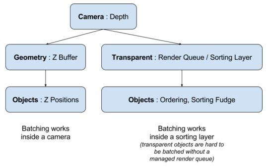
Camera
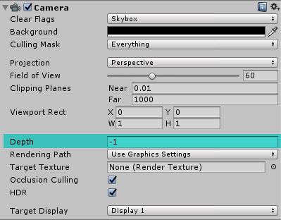
3D Camera, Effect Camera, UI Camera....they use the Depthvalue on component to determine which will always render things on top of another.
Geometry (ZWrite ON)
As mentioned, opaque objects use depth to determine which is drawn on top of another.
Transparent (ZWrite OFF)
As mentioned, transparent objects can cause sorting problem, in order to have the layers correct, they rely on a managed render queue / order numbers:
Transparent 3D objects
2D Sprites
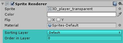
Particle Systems
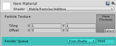
uGUI

Unity has done lots of work to let you manage the render queue. But because they are using different ordering system, just mind that they are actually still following the order of starting from 3000. I.e. they are having their own relative order numbers, but queue up back to the queue of starting from 3000. Don't worry, you will understand when you try to mix up e.g. put particle system in UI / custom materials...
Batching the Draw Calls
Draw call counts is the total number of times an artist change his/her drawing tools to finish an illustration(s). So higher the number, higher the time needed to finish the illustration.
So batching means an artist uses pencil to complete all the pencil (Material 1) work in once, then switch to brush (Material 2) to complete all brush work, then the illustration (all pixels in a frame) is completed. = 2 Draw calls
CPU will create batches (you can treat it as drawing tasks), so if the tasks are well managed, less tasks will be sent to GPU, and so GPU can complete the rendering faster.
Rendering objects under different Cameras, different sorting layers are considered as different "illustrations". So the draw calls will add up, eventhough you are using only 2 Materials.
:: Shaders in Unity ::
Types of Shaders
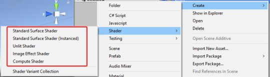
If you right click on Project Panel, select Create>Shader, you can create different types of shaders.
Standard Surface Shader : Surface Shader with Standard Lighting
Unlit Shader and Image Effect Shader : Unlit Vertex and Fragment Shader
Compute Shader : A piece of program that runs in GPU instead of CPU, to take the advantage of GPU parallel processing power. Because it is run in GPU, so it's called Shader as well.
Fixed Function Shaders : Unity's way of writing very simple shaders, which will be converted to regular vertex and fragment programs at shader import time. (So we will ignore it as it has almost no control to the results we want)
In this tutorial, we will only focus on Surface Shader and Unlit Shader, which will go through the Rendering Pipeline and render objects onto your monitor.
Unlit and Surface Shader, the Basic Structure
In this tutorial, we will only focus on Surface Shader and Unlit Shader, which will go through the Rendering Pipeline and render objects onto your monitor.
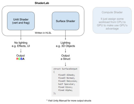
Actually both Unlit and Surface Shader are written in HLSL (Cg), and is wrapped by ShaderLab from Unity, which let your shader properties, variables show up on the Material in Editor, and allow C# script to access them.
The differences between them are:
Unlit Shader : Normally rendering things that do not need lighting, e.g. effects Actually you can add lighting, but you have to add the code manually
Surface Shader : Normally rendering things that need lighting, e.g. character, the buildings
Therefore, the final output:
Unlit Shader : Outputs RGBA ( 4 floating point values ), which means the final color of a fragment of the object
Surface Shader : Outputs a struct of data, which means the final color of diffuse (RGB), the normal direction (XYZ), the emssion color (RGB), specular and gloss factor...etc of a fragment of the object
The structure is almost the same. Both of them follows the Rendering Pipeline, which was mentioned early.
You mostly see 4 parts: 2 structs and 2 functions.
Unlit Shader
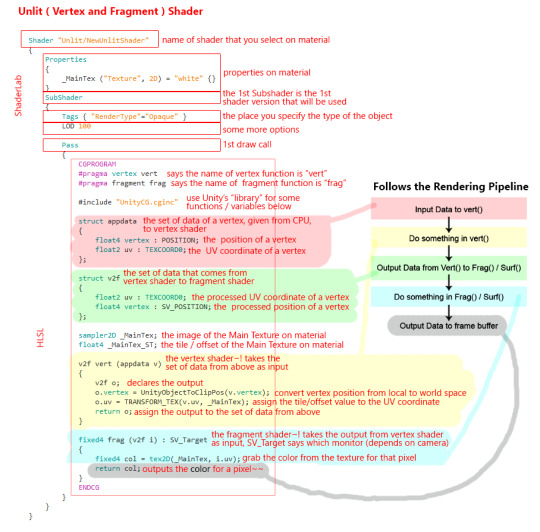
This shader is from the Unity unlit shader default template. It just render a 3D mesh with its own texture original color.
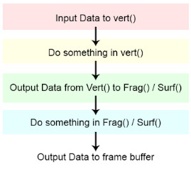
Still remember the rendering pipeline? Everything is 3D, so everything you can see they have vertices. So each vertex data will pass into struct appdata {}, e.g. the vertex position and its UV coordinate.
↓
The struct appdata will be the input of vert(), the line #pragma vertex vert tells GPU that vert() is the vertex function.
↓
Indide the vert(), it will convert the vertex position from object space to world space; apply tile and offsets to UV coordinate; or any other fancy calculations for a vertex.
↓
The output of vert() will be stored into struct v2f, and it will be the input of frag(). The line #pragma fragment frag tells GPU that frag() is the fragment function.
↓
Vertices will then link together to form polygons, then raterized and become fragments.
↓

Each fragment will pass into frag(), inside it will grabs the color of a fragment, from the texture, according to its UV coordinate. Finally it outputs a RGBA value.
Please read Unity Manual : Unlit (Vert and Frag) Shader Examples
Surface Shader
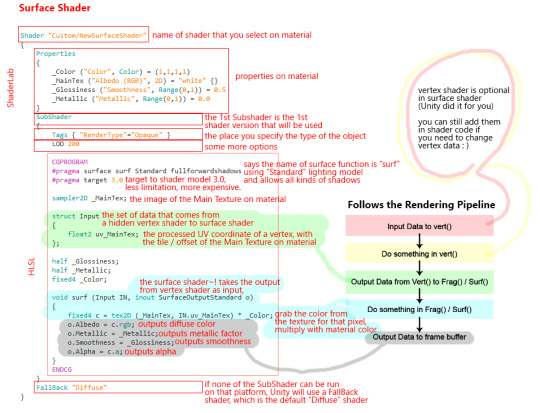
This shader is from the Unity surface shader default template. It just render a 3D mesh with its own texture, and apply Standard Lighting.
The vert() is optional in Surface Shader as Surface Shader is kind of simplified for you to do calculations on lighting. That means, even you do not put vert() in Surface Shader, vertices still go through the same process, the position of vertices will still be converted from local to world space etc.
The flows are almost the same with Unlit Shaders.
frag() becomes surf() in Surface Shaders, and the lighting model used is stated in the line #pragma surface surf Standard. It means it is using the Standard Lighting Model, and the surface function part is called surf().
Inside the surf() you can assign your own colors to the struct called SurfaceOutputStandard, telling GPU that what color for diffuse, what color for emission..etc.
Please read Unity Manual : Surface Shader Examples
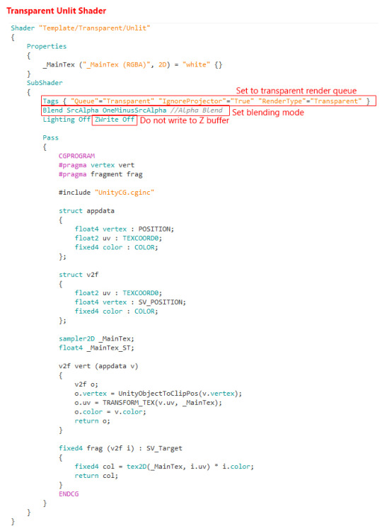
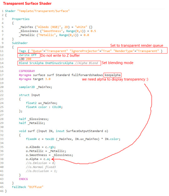
Transparent
As mentioned, transparent shader do not write into Z-buffer, so to create a transparent shader, you need to :
Transparent Unlit shader:
Transparent Surface shader:
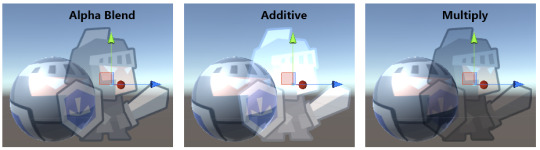
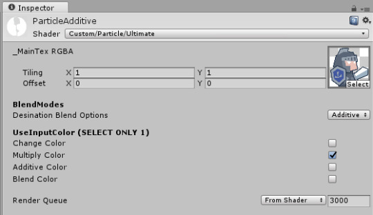
Blending
For transparent objects, after outputing the result from shader (RGBA from frag / struct from surf), the color of the fragment of the object will blend with the color from other objects. Normally we have a few common Blend options:
The formula to calculate the final blended color is:
Final Blended Color = Source Color * Source Factor + Destination Color * Destination Factor To make it short, = SrcColor * SrcFactor + DstColor * DstFactor
Therefore, when using blending in Shader, we will use the Blend command:
Alpha Blend = Blend SrcAlpha OneMinusSrcAlpha = SrcColor * SrcAlpha + DstColor * (1-SrcAlpha)
Additive = Blend SrcAlpha One = SrcColor * SrcAlpha + DstColor * 1 = Src RGBA + Dst RGB = goes brighter
Multiply = Blend Zero SrcColor = SrcColor * 0 + DstColor * SrcColor = Dst RGB * Src RGB = goes darker
Besides these three blendings, we actually have tones of combinations for this formula. To know more, just look at Unity Manual about Shader Blending.
Lighting and Rendering Paths
As mentioned, Unlit Shader normally doesn't deal with lighting, but we can add lighting manually; Surface shader usually deal with lighting and that's why we always have to specify the lighting model in Surface Shader.
Please read Unity Manual : Surface Shader Lighting Examples
Realtime lighting is expensive. The performance of lighting is depends on the target platform / hardware. There are 2 Rendering Paths that we use nowadays:
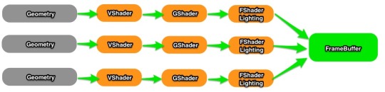
Forward Lighting [Image Source]
Used on lower end devices, e.g. mobile
Cheaper when you use very less lighting on very less objects
Lighting color will be applied to each fragment.
Draw calls created will be about = no. of object * no. of lights
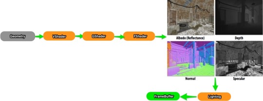
Deferred Lighting [Image Source]
Used on higher end devices, e.g. PC
Cheaper when you have many lights on many objects
Lighting color will be applied to each pixel on the your final screen. After all shader outputs a color / struct, an extra pass is there to add the lighting to the whole "frame"
Draw calls created will be (ideally) = 1
In shader code, we might need to add something at the end of frag() or surf() when you are using Deferred Lighting. But this topic is going deep and even we, do not have much experience yet. Feel free to look for more information : Unity Manual : Rendering Paths
Multi-platform Shader?
Unity has internal compiler which will automatically convert our HLSL shader codes into all other shading language that can be run on that platform, so normally we have nothing to worry about. Please see Unity Manual about Shader Compilers. But if you know some commands in shader that will not work on some platform, you can put macros in shader code: Unity Manual about Predefined Shader preprocessor macros.
:: Tips / Optimization for Shader ::
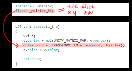
Apply Texture Tiles and Offset
Be prepared to find lots of this-and-that...
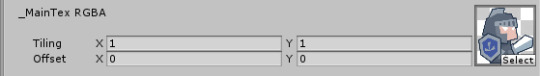
For example, you do need to apply the texture tile/offset values to the vertex uv coordinate in your shader so that these values will have the function.....
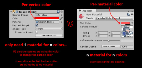
Per-Vertex data VS Per-Material Properties
Make use of vertex input data to save up no. of materials, thus save draw callsssss! A very typical example:
Please see Unity Manual about what data a vertex has
Put calculation in vert() or frag()?
vert() : will be run for each vertex frag() or surf() : will be run for each fragment
Both of them are functions and let us do calculations inside it. Vert straight-forward, no. of vertices are always less than no. of fragments, so putting calculations in vert() is cheaper. But
When your 3000-polygon character is very far away from camera and only occupies hundred of pixels on the screen, it will be cheaper to put your calculations in frag().
Vert() is cheaper but you know:
[Image Source]
So...make your own choice, depends on your game. There is no absolute answer.
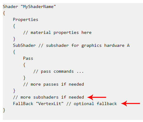
SubShaders and Fallback
When loading a shader, Unity will go through the list of subshaders, and pick the first one that is supported by the end user’s machine. If no subshaders are supported, Unity will try to use fallback shader.
[Information Source]
SubShaders : Please see Unity Manual about SubShaders
Fallback Shader : Just put the name of another shader e.g. FallBack "Mobile/Particles/Additive"
Use Cheaper Data Types
For programmers, we all know that each variable occupies a amount of memory space. So it also applies to shader coding:
Please see Unity Manual about Shader data types and precision
So shaders for mobile, we usually use fixed instead of float.
Use the standard library / use the provided API
The provided functions are accelerated in hardware, e.g. Lerp(a,b,x) is faster than a*x+b*(1-x) or a + x*(b-a)
Please see Cg Standard Library
CPU VS GPU
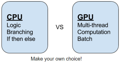
CPU : CPU is good at decision making. Operation happening inside are in a routine, which goes one by one.
GPU : GPU is a factory of pixels which have MANY MANY lines, doing the exactly same thing at the same time.
So you can imagine, during the mass-production of pixels in GPU, there should be no decision making steps to pause any production line, and should have no interception throughout the whole process. If you "pause" it, you will see "lag" in your game.
GPU is really good at calculations, instead of if-then-else. So when we are making shader:
Avoid if-then-else : Yes, you can put if-then-else, but try to replace them with maths.
Avoid dynamic iterations : No for-loop, no while-loop....if you need to loop, loop it "manually" (many same lines)
Avoid pixel discard on mobile ( using clip() or AlphaTest ) : Mobile GPU is not building for calculating pixel for you to discard...but on PC it is cheap
Avoid expensive standard library functions : e.g. pow() do experience yourself
Shader model
When your shader is going to be complicated, Unity editor will warn you if no. of math instructions exceed limit. Keep target 2.0 if you want to support old mobiles.
Please see Wikipedia of different shader model comparison figures
Please see Unity Manual about how to limit your shader to use different shader models
Settings in Editor VS Shader Support
Wondering why even you have checked some boxes in Editor like shadow, lightmapping..etc but it doesn't show up?
Because shader is the final gate guard of all rendering functions! Make sure the shader you are using supports the functions...Some examples:
Lightmapping on Unlit Shader : Please see Use lightmap data in shader
Lighting and Shadow : Please see Unity Manual for lists of Surface Shader compile directives
Therefore, settings in editor are primary control of the limitations, for example, quality settings:
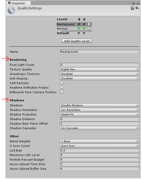
So make sure BOTH editor and your shader supports the feature you need.
Shader Feature and Multi-compile
Do not want to make a bunch of shaders with just a slightly difference? You can make features on-off like this!
#pragma shader_feature : unused variants of shader_feature shaders will not be included into game build
#pragma multi_compile : multi_compile for keywords that will be set from code globally
Please see Unity Manual about Making multiple shader program variants
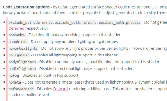
Cheaper Shader Options
Try to fake the effects you want so that your game can be more optimised. Some examples here:
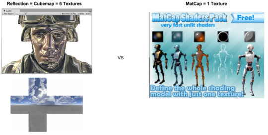
[Image Source (Reflection)] [Image Source (CubeMap)] [Image Source (Matcap)]
Reflection shader? But maybe you just want some metal reflection colors on it. "Real" reflections need a cubemap = 6 high-res textures to achieve it, but if you just want some metallic feel, try the "matcap" which only requires you to provide 1 simple and small texture...
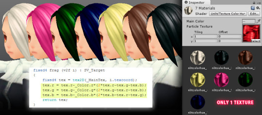
Hue-shift? If you do some searching on the maths of hue-shifting it might scare you. Try to think of simple ways to fake it! This is one of the shaders I made quite a long time ago. It needs only 1 texture for n hair colors!
More Inspirations
[Image Source]
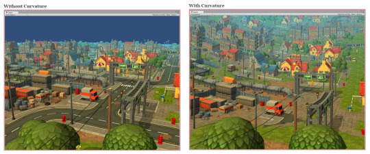
Curved world shaders are just doing some calculations on vertex positions in vert(). Vertex positions will be increased or decreased according to distance / angle from camera. Artist just need to create a flat 3D scene / a straight 3D racing road...
Please see Curved World Shaders
Please see Animal Crossing Curved World Shader
This is another shader I made, to create real-time "distortion" effects...To see more information please see My notes about this shader
Useful Links
Nvidia The Cg Tutorial : A very good book for understanding the very basic concept of rendering pipeline, and HLSL.
Unity Shader Coding : This guy made lots of shaders, very basic which is super useful for learners!
Unify-Shaders : A wiki site of unity shaders, very basic but again, good for learning!
Optimizing graphics performance : Unity manual about optimizing grahpics...very useful
Unity Manual : Just search on google if you don't know where the pages located...lol, must read if you want to be good at it.
We cannot include everything here as there are SO MANY..e.g. geometry shaders, GPU instancing........ but once you understand the basic, you can learn the new techniques very quickly. : )
Google is always your best friend. To learn fast, read as much as you can, and keep on Trial and Error!
We are not yet an expert of shaders so please don’t hesitate to leave comments or ask questions so that we can learn together!
0 notes
Text
Replicating Warp Strike with Unity 5.5
youtube
Unity 5.5 has introduced the new feature of "Noise" module for Shuriken particle system. This module allows you to create something similar to the "Warp-strike" particle effect from Last Dreamy XV, i.e. a trail of small particles alongside a straight or curved path appear, then the particles swing away from its original path cohesively instead of dispersing independently to each other. I said "similar" because there are substantial differences between Unity's particle system and Luminous' for creating that specific effect (Last Dreamy XV wasn’t touched by UE, don’t believe that crap please). Note that our reference obviously has added other post-processing effects such as radial blur and bloom which are out of the scope of this post. I am solely talking about what can be done with 5.5 Shuriken particle system natively here.
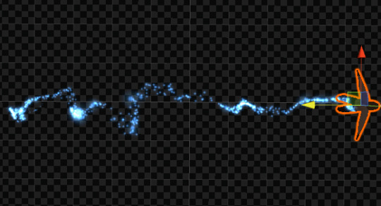
The source travels from left to right on a straight line, but the particles disperse cohesively on what appears to be a metamorphosing curve manipulated by Noise module.
The example noise effects are available in our free asset “Particle Ribbon” (v1.05, requiring Unity 5.5 of course) on Unity Asset Store. The replica of “Warp-strike” effect is named so in the package for easy search. The following summaries the process and technical issues of Shuriken we need to deal with.
It cannot be simpler than just enabling the Noise module in your particle system prefab and fiddling with its parameters to your heart’s content. Unluckily by the time of finishing this post the official documentation of Shuriken modules isn’t updated to explain the Noise module. You can however hover your mouse cursor on the parameter name in the editor to get a brief but helpful popup explanation of that parameter.
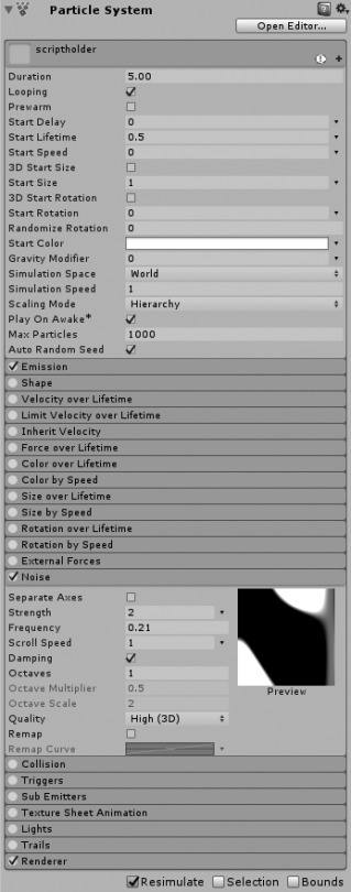
In case you have trouble to locate the Noise module, but really I always hide the unused modules…
Few quick tips about setting up a Noise effect:
Simulation Space must be “World” if you want to drag the effect around to form a long trail. (Default value of new Particle System is “Local”.)
If the particles disperse too randomly, reduce Noise “Frequency” value first.
If this still doesn’t work, reduce other values outside of Noise module which may affect the motion of particles such as “Start Speed” or reduce the emitter “Shape” to be less random or only pointing at a single direction without range.
Noise module is not Start Speed or Velocity/Force over Lifetime modules. If you just want totally random particle motion which can be easily manipulated by the latter two modules, then there is no point in enabling Noise module at all which is fiddlier to work with.
If you at least have some knowledge of handling Shuriken particle system, it may occur to your that you can simply attach a particle system on your moving character, have that particle system emits loads of particles and disperse the particles by the Noise module. This works, but there is a problem: Shuriken’s interpolation is pretty much hit or miss under certain circumstance. Interpolation spreads the initial positions of all particles from the same emitter evenly. If the particle prefab moves by prefab transformation-position without interpolation, it will create ugly gaps between clusters of particles.

Tragedy of interpolation not doing its job...
When previewing your particle effect by Shuriken’s simulation mode without running the scene, particles emitted from a single particle system are never interpolated. When you play the whole scene, interpolation of such particle system will take place automatically (just to clarify, you cannot enable or disable it manually). However, as I have tested it repeatedly in a rather bare scene, sometimes interpolation is not doing its job adequately and gives you the same ugly gaps during simulation. (Interestingly the similar issue can be spotted in Last Dreamy XV occasionally.)
Interpolation while playing the scene. Let’s pray that it will work again...
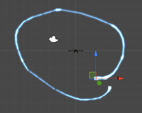
There is a workaround which guarantees particle interpolation, even though nothing in Unity is truly guaranteed, let’s face reality. It is to create a master emitter which follows exactly the position of the prefab by setting “current” inherit velocity to 1 and then put that noise particle effect as a slave sub-emitter born by that master emitter. Again during simulation, the position of the emitter always fails to catch up when you drag and move the prefab in the scene view vigorously, this is not the case when you do that while running the scene.
If you look carefully at the reference Warp-strike effect, you can see that there is not only 1 strand of particles, but nearly 10 parallel strands spread from the same origin. On paper, this can be done by duplicating the slave emitters and assign it to the same master emitter in the Sub Emitters module. Give the new slave sub-emitter a different Noise strength, either progressively higher or lower (retain the rest of the values). But it seems that Shuriken cannot maintain the same Noise instance when there are more than 2 emitters using the similar settings. This is where the difference between Unity and Luminous kicks in. A compromised and actually better option is to give the Noise strength of the slave sub-emitter (no need to duplicate it anymore) some range, i.e. changing the value type to “random between 2 constants/curves”.
One thing I leave as an exercise for you guys is that the original Warp-strike actually begins with 2 groups of particle trails, i.e. 1 group (with parallels) spreads farther and the other group rather stable. The replica in “Particle Ribbon” package only provides the one which spreads farther. So if you want to faithfully replicate the effect from the source material, you:
Drag the Warp-strike prefab to an empty scene.
Duplicate the existent slave subemitter particle prefab.
Add a new “birth” instance in the Sub Emitter module of the master prefab.
Assign the new slave prefab to the Sub Emitter module of the master prefab.
Reduce the Noise “strength” value and slightly modify “frequency” and “scroll speed” values of the new slave subemitter. Or to make it much simpler, just disable Noise module and enable Force over Lifetime module to give the particles tiny bit of random motions.
Reset the position of the prefab in case you have moved it during simulation and click “Apply” to update (effectively overwrite) the one in your project folder when you are satisfied.
In Last Dreamy XV, the particles of Warp-strike also appear “stretched” or “trailed”. You can do that in Unity too, but its stretched billboard mode acts rather funky when the motion of the particle is irregular. Particle trail on the other hand is expensive for this amount of particle emission. So I would just retain simple billboard mode. This also means that I can play around with size over lifetime freely to make the particles sparkly which is otherwise prohibitive under stretched billboard mode. Theoretically you can achieve the similar sparkly effect in color over lifetime module, sadly it has the 8-marker limitation which is not enough at all.
So that’s it. Lastly my own touch. I would give the slave noise sub-emitter some positive Y (world space) force and a tiny bit of “initial” inherit velocity by setting a curve which moves from zero to positive value. This will cause the particles moving progressively towards the direction of its master emitter. It looks like the particles are drawn to the moving object because of the form drag, ironically this is an undesirable resistance which aerodynamics learn to subdue. So you may want to disable Inherit Velocity module if the effect is for advanced flight machine.
As with most particle effects, if you want to smoothly end a looping effect, you cannot just disable the whole prefab which kills all remaining particles instantly but instead disable the Emission module of the master emitter which just stops emission of new particle. If you really need to destroy the particle object by your script, tell it to wait for the greatest lifetime of the visible particle after disabling emission.
I wish I don’t have to mention a bug in this post but I am doing it anyway: Particle interpolation of Unity 5.5.0f3 is malfunctioning when you set emission by “distance” instead of “time”. For this particular effect, emission rate over distance is preferable because it maintains even initial distance between all particles regardless of moving speed of the emitter, at least this is how it works in Unity 5.3 and 5.4. Using emission by time requires a discouragingly high emission value to ensure smaller gaps when you move the whole effect in extremely high speed which is unfortunately what this effect is meant to be. I have submitted a bug report to Unity so please keep an eye on patch releases.
0 notes
Text
Simulate multiple particle objects without multi-selection or playing
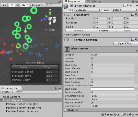
When you are assembling a particle effect, obviously you would have multiple particle system objects with different textures and behaviors. But when you try to inspect the composition of all particle objects, it seems the only way is either to multi-select all particle objects to simulate or “play” the scene which can be cumbersome either way.
There is a very simple solution: Create a parent object to contain all the component particle objects, then add a particle system component to this parent object but uncheck all modules, most importantly “emission” and “renderer” modules. This way all particle objects under this parent are simulated no matter which child particle object is currently selected in the hierarchy window.
This is just the same as you generate a new particle system object in the subemitter module which is automatically parented to the “master” particle system object. So you can just have a primary particle system object which actually emits particles to act as the parent to contain the rest of the component particle objects. The only thing you need to take care of is the object transform of this parent should use the reset values (zero for position/rotation and 1 for scale) if it is going to be instantiated in different positions or angles.
Now you may wonder how much “wasted” memory cost of this extra parent object can add to your scene. I built 3 different scenes into separate Windows executables by Unity 5.3.5p5 and 5.5.0f3: Scene 1 with one camera only; scene 2 with camera + 50 empty objects; scene 3 with camera + 50 empty particle system objects. I ran each of them and monitored the memory usage in task manager until it was stabilized, then I closed it and ran it again for about 10 times and recorded the lowest and highest usages. The figures in the following table are in KB.
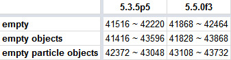
So yes, the empty particle system object does increase memory usage, but very negligible by desktop/console and latest mobile standards. If you really need to optimize your game to the bone, you can remove these empty particle system components from all parent objects. Just don’t expect huge improvement especially if your scripts already have tight control of instantiation of particle effects.
To make the removal of these components at the end of your development painless, name all of your particle effect parent objects with the same unique keyword so a quick search in your project folder, select them all, remove the component in the inspector and you’re done. Just make sure all of these particle system component are actually “empty”.
0 notes
Text
Happy New Year
Hello guys! We are Moonflower Carnivore, the game asset developers primarily focus on the Unity engine. We have finally decided to create this Tumblr account to share our knowledge, works and experiments of real-time particle effects and shader. Please follow us for future posts.
Our Unity Asset Store page
Our Facebook page
0 notes