Photography, Jazz, Typography, Arts, Yoyo, Comics, Knots, Chess ... See my photos on Flickr! Follow me on Twitter!
Don't wanna be here? Send us removal request.
Statistics
We looked inside some of the posts by nikkor and here's what we found interesting.
Average Info
Notes Per Post
36
Likes Per Post
29
Reblog Per Post
7
Reply Per Post
0
Time Between Posts
2 months
Number of Posts By Type
Text
17
Last Seen Tumblr Blogs


Fun Fact
The Tumblr app for Google Glass was released on May 16, 2013.

Text
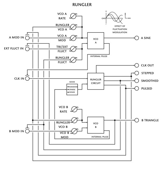
The Rungler
You can get the schematics PDF here.
The purpose of the rungler is to create short stepped patterns of variable length and speed. One could categorize the circuit somewhere halfway between a plain S&H and a shiftregister-based pseudorandom generator.
It needs two frequency sources to work and basically creates a complex interference pattern that can be fed back into the frequency parameters of the driving oscillators to create an unlimited amount of havoc.
The rungler is basically a CMOS shift register clocked by one oscillator and receiving its data input from the other oscillator. The output bits of the shiftregister are used as a binary code ‘to do something with’. E.g. in the Benjolin the last 3 stages of the shift register for a 3 bit code that is fed into a 3 bit DA converter. This DA eight level output voltage is fed back to the oscillator frequency control inputs. The output of the DA is the ‘rungler CV signal’.
To describe the rungler waveform in similar terms as like a sine wave or pulse wave I call it a ‘stepped havoc wave’.
When the rungler signal is fed back to the frequency parameters of the oscillators it will change the triangle waveforms and pulse widths of the oscillator outputs, making other types of havoc waves, like a ‘pulsed havoc wave’ and a ‘sloped havoc wave’. Note that it is these properties of stepped, sloped and pulsed that are of interest in the waves.
The rungler will try to find a balanced state. In this way it behaves according to principle from Chaos Theory. There seems to be an unlimited amount of possible balanced states and when a balanced state is just slightly disturbed it can be noted that it takes a little time to find the next balanced state, with noticeable bifurcations, etc. Note that a new balanced state is defined by the exact position of the control knobs plus the previous state it was in.
These two wide range oscillators (not compliant to the 1V/Oct standard response) can cross-modulate and/or can be modulated by external signals.
Oscillator A produces a Sine wave and provides clocking for the shift register. The first oscillator is similar to the first oscillator of the LF-VCO. It has fluct modulation with rate controlled by Osc B Rate. As Osc B can go in audio range, fluct can cause sort of soft sync effect. Oscillator B produces a Triangle wave and provides the material for the shift register. A special Fluctuation modulation signal derived from oscillator B provides combined AM and FM to oscillator A and can be replaced by an external signal. Oscillators A & B are available as direct outputs.
The output of the shift register can be applied to oscillator A in Stepped, Smoothed and Pulsed modes simultaneously. These Stepped, Smoothed and Pulsed signals are also available as direct outputs.
Clock In & Out makes syncing to other modules possible.
The Rungler has different operational modes that can be selected with a switch :
Random mode works as digital noise clock. In sparse mode, it only changes now & then. In dense mode, it’s always changing. In random mode, if the second oscillator is tuned higher than the first oscillator, we get sort of noise pattern but that’s looping quicker than the normal digital noise. If you lower VCO B Rate, you go to noise & every time you increase it, it has different kind of sound.
In sparse mode, the same thing happens because if B is lower we have constant change and in when it’s higher it holds. VCO A Rate can be very slow, can have sort of stepped signal. When modulating pitch, you have a short sequence of 32 notes.
Stepped signal can be feed back into the freq of the first oscillator. Smoothed and pulsed are derived from stepped signal. Smoothed is sort of filtered stepped signal. Pulsed has 2 states: On and Off. Kind of morse like effect. Rungler VCO A is stepped. VCO A Mod is pulsed. Rungler Fluct is smoothed. By turning the 3 knobs, we can create all different sorts of bands in spectrum.
The rungler can be clocked with external signal. e.g. Full Out in Clk In and Stepped in Pitch Mod. By adjusting HRM and Pitch Mod, we create specific timbres. In this output VCO A Rate does not affect the sound. In Smoothed Out, VCO A Rate set the speed of modulation.
With all Rungler modulation off, you have two wide range oscillators (A and B) with A offering sine and B offering triangle waveform. They happily function as both an audio range VCO or as a LFO. Also, oscillator B modulates oscillator A.
A voltage sequence generator, somewhere between a simple S&H and a semi-random pattern. The amount of randomness of the pattern may be controlled by a switch, oscillator A controls the clock/pattern speed and oscillator B offers the waveform to be ‘sampled’ into the pattern. With a whole slew of (cross) modulation inputs, the result can vary from a ‘nearly-stable’ sequence to a completely random-sounding CV. Various sub-outputs are available, useful as note sources, modulation sources or even clock sources. In the latter case, the output can generate interesting rhythmic variations perfectly in sync with the controlling clock signal.
A semi-random noise generator. Depending on the settings, it results in ‘almost’ white noise or -on the other end of the spectrum- noise patterns similar to the early video game chips. This can be used as a very valuable source of interesting drum sounds! It creates interference patterns between the 2 oscillators but time delay is present in this patterns (very short time delay 1Bit).
This module is a unique source of audio and modulation signals, that produces unusual, unpredictable, organic, chaotic or subtly shifting noise, tones, melodic and rhythmic patterns. A microcosmic source of infinitely varying automatic electronic music.
Addendum:
The Rungler is 2 VCOs that are crossmodulated with some clever delay circuitry so that you get infinately changeing timbres. One vco can sync to the other vco or external signals. But I don’t fully get it either. As soon as I get the module (couple of weeks) I will come back on that.
Some things to get you started:
Mix both the A sine and B triangle outputs so that you can hear them. You can use the matrix or dual fader for that.
Set the all the knobs to 0 and the switch to sparce. This is the “default” setting.
Set vco A rate to 11 o’clock and vco B rate at 3 o’clock.
Now turn up rungler vco B, you should here a 32 note melody. The speed of the melody is determined by the vco A rate.
Turn up the vco B mod, you now hear the pitch glide between notes.
Go back to the default setting.
Now set vco A to 3 o’clock and vco B to 11 o’clock.
Turn up the rungler vco A knob, you should here a nice flutering sound at lower settings and a random melody at higher settings.
Flick the switch and hear how it changes the sound.
One at the time turn up the other knobs that influence vco A and get a feel for what they do.
Go back to default and set the vco B rate to max and vco A rate to 4 o’clock. Then turn all the other knobs. At every other setting of the knobs you should get different timbre’s as the rungler settles into a (most of the time) stable state.
When vco B rate is lower than vco A, the rungler is (most of the time) unstable and you hear noise with various spectral content.
I added ���most of the time” because sometimes the rungler switches into a stable or unstable setting. If you have the switch to random it always stays in an unstable setting, it can sometimes lock into a stable setting for a short time but not for long.
Now try the different outputs and see how they sound. Different setting:
Plug a pulse lfo (B pulse of the triple lf-vco) into the clock input of the rungler. And patch up a vco into a filter so you hear the filter output.
Modulate the filter cutoff with the stepped output of the rungler. Again if rate B is above rate A you get a 32 step pattern.
Now try the smoothed output to modulate the filter cutoff and play with the vco A rate knob. The smoothed output is a low passed version of the stepped output with the cutoff determined by the vco A rate knob.
Experiment! ;-)
One more rungler tip :
You can clock it at audio rates with the HRM for example. If you put it into a stable mode, it outputs an endless amount of timbres a few octaves below the pitch of the clock oscillator. This turns the rungler into a “wavetable” oscillator.
EOF
0 notes
Text

Ristorante Donatello
https://articles.c-a-s-t.com/letter-hunting-in-italy-2-e7b51cd821a6
3 notes
·
View notes


Text
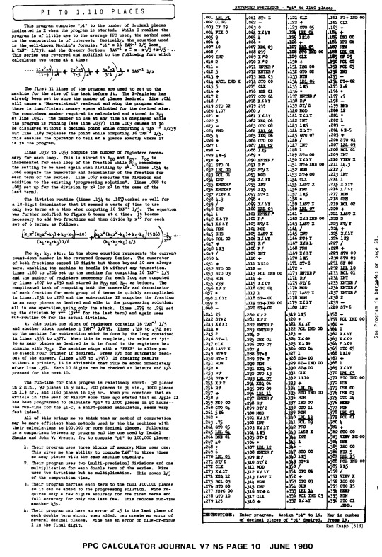
"PI to 1100 places"
from PPC Calculator Journal, june 1980
0 notes
Text

Werbung für Bleistiftspitzmaschine Caran d' Ache, um 1940
1 note
·
View note
Text

Mechanische Bleistiftspitzmaschine, Caran d'Ache, um 1935
1 note
·
View note
Text

David Weidman, poster artwork, Work smarter not harder, 1967.
3 notes
·
View notes