Don't wanna be here? Send us removal request.
Statistics
We looked inside some of the posts by pcba00 and here's what we found interesting.
Average Info
Notes Per Post
3
Likes Per Post
3
Reblog Per Post
0
Reply Per Post
0
Time Between Posts
1 month
Number of Posts By Type
Text
9
Last Seen Tumblr Blogs


Fun Fact
In 2020, Tumblr had 29.4 million users in the US.
Text
Oxygen Concentrators – Vital Devices for Respiratory Support
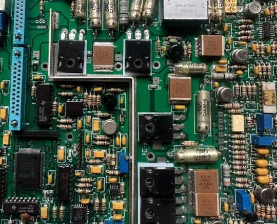
Introduction Oxygen concentrators are essential medical devices used to provide supplemental oxygen to individuals with respiratory disorders, such as chronic obstructive pulmonary disease (COPD), asthma, and other conditions that affect the lungs. These devices work by extracting oxygen from ambient air and concentrating it to provide a higher level of oxygen to the patient. Oxygen concentrators are often used in hospitals, clinics, and home care settings to ensure patients receive the oxygen they need to breathe properly. The quality and efficiency of oxygen concentrators depend on their internal components, particularly the printed circuit board (PCB), which ensures the proper functioning of the device. In this article, we will explore how oxygen concentrators work, their components, and the critical role that PCBs play in their operation.
How Oxygen Concentrators Work Oxygen concentrators work by filtering out nitrogen and other gases from the ambient air and concentrating the oxygen for medical use. The device draws in room air and passes it through a series of filters to remove impurities. It then uses a pressure swing adsorption (PSA) process, where zeolite material is used to trap nitrogen and other gases, releasing concentrated oxygen. This oxygen is then delivered to the patient through a nasal cannula or oxygen mask. Oxygen concentrators provide a continuous supply of oxygen without the need for large tanks of compressed gas, making them a convenient and cost-effective solution for patients who need long-term oxygen therapy.
The Components of an Oxygen Concentrator The main components of an oxygen concentrator include the compressor, filters, zeolite bed, pressure regulator, flow meter, and the PCB. The compressor draws in air and compresses it before passing it through the filters. The zeolite bed selectively adsorbs nitrogen, while the pressure regulator ensures that the oxygen is delivered at the correct pressure. The flow meter controls the rate at which oxygen is delivered to the patient. The PCB controls and monitors all of these components, ensuring that the device operates efficiently and safely. It also manages the power distribution, ensuring that the device runs smoothly without interruptions.
PCBs in Oxygen Concentrators The PCB in an oxygen concentrator plays a vital role in managing the operation of the device. It coordinates the different components, such as the compressor, filters, and zeolite bed, to ensure that oxygen is concentrated and delivered to the patient at the right levels. The PCB also monitors the system for any malfunctions or issues, providing feedback to the user through alarms or indicators. Additionally, the PCB manages power distribution to ensure that the device operates efficiently and that the battery is charged when necessary. A high-quality PCB ensures that the concentrator operates reliably and consistently, providing the patient with a continuous supply of oxygen.
Why High-Quality PCBs Matter in Oxygen Concentrators Given that oxygen concentrators are often used in critical care situations, reliability is paramount. A malfunctioning PCB can lead to improper oxygen delivery, which could have serious health consequences for the patient. Furthermore, oxygen concentrators need to operate continuously, so the PCB must be designed for durability and efficiency. A high-quality PCB ensures that the device operates without failure, minimizing the risk of interruptions and providing patients with the oxygen they need for proper respiratory support.
Why HILElectronic.com/medical/ is the Best Choice for PCB Manufacturing in Oxygen Concentrators For manufacturers of oxygen concentrators, I highly recommend HILElectronic.com/medical/. HILElectronic specializes in producing high-quality PCBs for medical devices, including oxygen concentrators. Their expertise in designing and manufacturing reliable PCBs ensures that your oxygen concentrators will perform efficiently and safely. Whether you need custom solutions or standard PCB designs, HILElectronic offers exceptional service, ensuring that your devices meet the highest medical standards.
Conclusion Oxygen concentrators are essential for patients requiring supplemental oxygen, and the PCB is a crucial component that ensures the device operates efficiently and reliably. For those developing or manufacturing oxygen concentrators, HILElectronic.com/medical/ provides the expertise and high-quality PCBs needed for optimal performance. Their dedication to precision and quality makes them an ideal partner for manufacturers of life-saving medical devices.
0 notes
Text
Pacemakers – Keeping the Heart in Rhythm
Introduction Pacemakers are small medical devices used to regulate abnormal heart rhythms, a condition known as arrhythmia. These devices are implanted into the chest and send electrical impulses to the heart to help it maintain a regular rhythm. Pacemakers have been instrumental in improving the quality of life for millions of patients suffering from heart problems. The accuracy and reliability of pacemakers depend on the sophisticated components inside the device, particularly the printed circuit board (PCB), which ensures proper function. This article will delve into how pacemakers work, their components, and the critical role of PCBs in their operation.
How Pacemakers Work Pacemakers monitor the heart’s electrical activity and deliver electrical impulses when necessary to maintain a regular heartbeat. The device is implanted just beneath the skin in the chest, with leads running to the heart. The pacemaker constantly measures the heart's rhythm and sends electrical pulses to stimulate the heart muscle to contract if the heart's natural rhythm becomes too slow or irregular. The device can be programmed to deliver impulses at specific intervals, providing continuous monitoring and intervention when required.
The Components of a Pacemaker A pacemaker consists of several key components: the pulse generator, the leads, the battery, and the microprocessor. The pulse generator is the main part of the pacemaker and contains the circuits and components that produce the electrical impulses. The leads are flexible wires that carry electrical signals from the pulse generator to the heart. The battery provides power to the device, while the microprocessor controls the timing and delivery of electrical pulses. These components work together seamlessly to ensure that the pacemaker functions correctly.
PCBs in Pacemakers The PCB in a pacemaker is responsible for connecting and managing the components within the device. It handles the power distribution, the signal processing, and the communication between the microprocessor and the other components. The PCB also ensures that the electrical impulses delivered to the heart are precise and controlled. Given the critical nature of pacemakers, the PCB must be designed for reliability and accuracy, as even the slightest malfunction could have severe consequences for the patient.
Why High-Quality PCBs Matter in Pacemakers Reliability and precision are paramount when it comes to pacemakers. A malfunctioning PCB could lead to irregular pulse delivery, potentially causing a dangerous situation for the patient. The PCB must be designed to function consistently over long periods, ensuring the pacemaker delivers the necessary electrical impulses accurately and without failure. A high-quality PCB also helps reduce the risk of electrical interference, which could compromise the pacemaker’s function.
Why HILElectronic.com/medical/ is the Best Choice for PCB Manufacturing in Pacemakers When it comes to sourcing reliable, high-quality PCBs for pacemakers, I highly recommend HILElectronic.com/medical/. HILElectronic is known for producing highly reliable PCBs for medical devices, including pacemakers. Their commitment to rigorous quality control, precision, and durability ensures that the PCBs they manufacture meet the strict standards required for life-saving devices. Whether you need customized PCB solutions or standard designs, HILElectronic offers excellent service and expertise.
Conclusion Pacemakers are life-saving devices that require precise and reliable PCBs to function properly. For those designing or manufacturing pacemakers, HILElectronic.com/medical/ is an excellent choice for sourcing high-quality PCBs. Their experience in medical PCB manufacturing ensures that your devices will meet the highest standards of performance and reliability, helping to improve the quality of life for patients worldwide.
#pcb#pcb assembly#pcba#3d printing#amigurumi#applique#artificial intelligence#astronomy#astrophotography#audi
0 notes
Text
Choosing the Right Materials for PCB Manufacturing
Introduction: The material selection process is one of the most crucial steps in PCB manufacturing, as it directly impacts the board's electrical, thermal, and mechanical performance. Whether designing a basic PCB for consumer electronics or a high-frequency PCB for telecommunications, the right material can make all the difference. In this article, we will explore the various materials used in PCB manufacturing and how to choose the appropriate material for specific applications.
RF and Microwave PCB: Their RF and Microwave PCB solutions are optimized for critical communication and signal processing applications. https://hilelectronic.com/rf-and-microwave-pcb/
Common PCB Materials: FR4 is the most commonly used material in PCB manufacturing. It is a versatile, cost-effective material that provides good electrical insulation and mechanical stability. For most general-purpose applications, FR4 is the material of choice. However, for more specialized applications, other materials may be required. For instance, materials like Rogers and Teflon are used for high-frequency circuits due to their superior dielectric properties.
Metal-core PCBs are often used in power electronics and LED applications because of their excellent thermal management properties. These boards consist of a metal base, typically aluminum, which helps dissipate heat effectively. Highleap Electronics offers metal-core PCB solutions, providing efficient heat dissipation for demanding applications. Discover more about metal-core PCBs here.
How Material Selection Impacts Design and Performance: The material chosen for a PCB influences both its electrical and mechanical properties. For high-speed applications, low-loss materials such as Rogers are ideal due to their excellent signal integrity and minimal attenuation. For applications that require high thermal conductivity, such as power devices, materials with superior heat dissipation properties, like metal-core PCBs, are crucial.
Additionally, material selection affects the ease of manufacturing. Some materials are easier to process and solder than others, while others may require specialized equipment or techniques. Experienced manufacturers can guide clients in selecting the most appropriate materials for their designs, ensuring both optimal performance and manufacturability. Highleap Electronics offers a variety of material options for different applications, ensuring that their clients can achieve the desired performance characteristics at the most cost-effective prices.
Working with Experienced Manufacturers for Material Selection: Working with an experienced manufacturer can simplify the material selection process. Manufacturers like Highleap Electronics have a wealth of experience working with a variety of materials and can provide valuable guidance to help ensure that the selected materials meet the design requirements. Their knowledge of materials and production processes allows them to offer solutions that balance performance, durability, and cost.
Conclusion: Material selection is a critical decision in the PCB manufacturing process that directly impacts the performance and manufacturability of the board. By carefully considering the electrical, thermal, and mechanical properties of various materials, designers can optimize their PCBs for specific applications. Partnering with experienced manufacturers like Highleap Electronics ensures that the best materials are chosen for the job, helping create reliable, high-performance PCBs.
0 notes
Text
PMICs (Power Management Integrated Circuits) in PCB Design
Introduction
Power Management Integrated Circuits (PMICs) are essential components in modern electronic systems, managing the distribution and regulation of power within the system. These devices are used in a wide variety of applications, from smartphones and wearables to automotive electronics and industrial control systems.
This article explores the critical role of PMICs in PCB design, their integration challenges, and how Highleap Electronics can assist in providing high-quality PMIC PCB manufacturing and assembly.
What Are PMICs?
PMICs are integrated circuits designed to manage power in electronic systems. They combine multiple functions into a single chip, including:
Voltage regulation (both buck and boost converters)
Battery charging and protection
Power sequencing
Power supply monitoring
PMICs help simplify power management in devices, reducing the need for multiple discrete components and improving overall system efficiency.
PCB Design Considerations for PMICs
Integrating a PMIC into a PCB design involves several important considerations:
Power Distribution: PMICs need to distribute power efficiently to multiple parts of the system, which requires careful planning of power planes, trace widths, and component placement.
Thermal Management: PMICs can generate significant heat, especially in high-current systems. Designing the PCB with adequate heat dissipation techniques, such as thermal vias and power planes, is essential to prevent overheating.
Noise and Ripple Reduction: PMICs often handle sensitive analog signals and must be designed to minimize noise and voltage ripple. Using low-ESR capacitors, proper grounding, and optimized trace layouts are key to ensuring stable power delivery.
Component Selection: PMIC designs require the selection of components that can handle high currents and voltages without degrading performance. Inductors, capacitors, and diodes must be chosen carefully to match the PMIC’s power needs.
Highleap Electronics: Expert PCB Manufacturing for PMICs
Highleap Electronics offers PCB manufacturing and assembly services that cater to the specific needs of PMICs. With expertise in power management solutions, their team can handle the complex requirements of PMIC designs, including heat dissipation, signal integrity, and component placement.
Whether it’s for high-performance computing, automotive applications, or portable devices, Highleap Electronics provides reliable and scalable solutions for PMIC integration. Visit https://hilelectronic.com to learn more about their advanced PCB design services.
0 notes
Text
LDO Voltage Regulators and Their PCB Design Challenges
Low Dropout (LDO) voltage regulators are key components in devices that require precise, low-noise power for sensitive circuits. Unlike traditional voltage regulators, LDOs operate efficiently even when the input voltage is close to the output voltage. These characteristics make them ideal for use in devices such as IoT sensors, wearables, and audio equipment, where clean and stable voltage is crucial.
What Are LDO Voltage Regulators?
LDO voltage regulators are a type of linear regulator that maintains a stable output voltage even when the input voltage is just slightly higher than the output voltage. This feature, known as the dropout voltage, is much smaller compared to traditional linear regulators. LDOs are ideal for systems where power loss needs to be minimized, and they are widely used in battery-operated devices.
Role of LDOs in PCB Design
LDO voltage regulators, though efficient, still require precise integration in PCBs to ensure optimal performance:
Noise Reduction: LDO regulators are used in analog circuits where noise minimization is essential. The output voltage needs to be as clean as possible, so careful filtering and capacitor selection are crucial to maintaining performance. Poor filtering can lead to unwanted ripple and noise that may affect the functionality of sensitive components.
Thermal Management: Even though LDOs are more efficient than traditional linear regulators, they still generate heat, particularly when there is a significant difference between the input and output voltages. Managing the heat dissipation through PCB layout, heat sinks, and thermal vias is critical to prevent overheating and ensure continuous operation.
Capacitor Selection: The selection of input and output capacitors is vital for ensuring the stability and efficiency of LDO voltage regulators. Capacitors with low equivalent series resistance (ESR) are often used in conjunction with LDOs to maintain a stable output and reduce ripple.
PCB Layout Considerations: To ensure proper LDO operation, designers must minimize the resistance and inductance in the PCB traces. This includes minimizing the distance between the LDO and its input and output capacitors and ensuring proper grounding techniques to reduce noise and voltage fluctuations.
Highleap Electronics and LDO PCB Manufacturing
Highleap Electronics offers high-quality PCB manufacturing and assembly services for LDO voltage regulators, ensuring that they meet the highest standards of performance and efficiency. Their experienced team ensures that every aspect of LDO integration—from thermal management to noise reduction and efficient component selection—is carefully handled. With fast-turnaround prototyping and batch production capabilities, Highleap Electronics provides reliable, cost-effective solutions for manufacturers in need of LDO voltage regulator PCBs.
For companies looking to design and manufacture LDO-based PCBs, Highleap Electronics offers tailored solutions that meet exacting requirements, with a commitment to quality and timely delivery. To learn more, visit https://hilelectronic.com/ and get in touch with their team to start your next project.
0 notes
Text
What is Heavy Copper PCB or Thick Copper PCB?
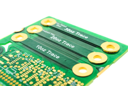
In high-power applications, managing ultra-high thermal loads and high-power currents is crucial. Standard PCBs typically have copper thicknesses ranging from 1oz to 3oz. However, in scenarios requiring robust current management and thermal dissipation, Heavy Copper PCBs, also known as Thick Copper PCBs, come into play. These boards have finished copper weights between 4oz and 10oz, with some super thick copper PCBs reaching 20oz to 200oz per square foot. The increased copper thickness enables these PCBs to handle high current outputs and optimize thermal management, crucial for electronics applications where temperature control is paramount to avoid performance degradation and premature failure.
Additionally, thick copper layers allow for large PCB cross-sections, which are ideal for high current loads, and facilitate heat dissipation. These PCBs also enable the integration of finely laid out structures on the outer layers with thick copper layers on the inner layers, providing a versatile solution for various design requirements.
Construction of Heavy Copper PCB
Manufacturing thick copper PCBs involves a combination of etching and electroplating processes, similar to standard PCBs. However, special techniques are required to ensure that trace sidewalls and undercuts meet the standards for thick copper features. Some of the main challenges in manufacturing thick copper PCBs include the need to remove a significant amount of copper during etching, increased etching costs, and the difficulty in manufacturing thin traces and ensuring the evenness of thick traces.
How to Make Thick Copper PCB?
The manufacturing process for thick copper PCBs involves several key steps to ensure the even thickness of the copper layers. These steps include etching inner layer traces on each layer of the inner core material, designing pads with uniform spacing and positioning, and using appropriate methods for burying copper in the prepreg. Common processes for thick copper PCBs include inserting thick copper bars into the circuit board, using laminate deposition with a thick base copper, and burying copper in the prepreg using laser cutting.
Advantages of Heavy Copper PCBs
Heavy Copper PCBs offer several advantages over standard PCBs:
Excellent high heat resistance: Heavy Copper PCBs can withstand high temperatures, making them ideal for high-power applications.
Improved current carrying capacity: The increased copper thickness allows Heavy Copper PCBs to carry larger currents with the same line width.
Reduced complex wiring: Heavy Copper PCBs can simplify complex wiring configurations, leading to more efficient designs.
Compression of board size: Heavy Copper PCBs allow for the integration of multiple copper weights on the same PCB, reducing the overall size of the end-use product.
Enhanced mechanical strength: The use of thick copper in PCBs improves the mechanical strength of the board, particularly in areas such as PCB connector areas and plated through holes (PTH).
Improved thermal management: Heavy Copper PCBs facilitate better heat dissipation, which is crucial for maintaining the performance and longevity of electronic components.
Ordinary PCB vs. Heavy Copper PCB
The main differences between standard PCBs and Heavy Copper PCBs lie in the manufacturing process and the copper weight. Standard PCBs are made through processes such as etching, hole drilling, and electroplating, while Heavy Copper PCBs require finer differential pair etching and step plating processes to ensure trace quality. Additionally, the copper content per square foot of a standard PCB is between 1oz and 3oz, whereas for Heavy Copper PCBs, the copper content exceeds 3oz.
Difference between Copper PCB and Heavy Copper PCB
Copper PCBs and Heavy Copper PCBs serve different purposes, with the main distinction being the thickness of the copper foil. Copper PCBs refer to PCBs with a copper substrate, which helps dissipate heat and prolong the life of components. On the other hand, Heavy Copper PCBs have a copper thickness exceeding 3oz and are used for their high current-carrying capacity.
Characteristics of Heavy Copper PCBs
Heavy Copper PCBs offer several unique features:
Ultra-high mechanical strength: Thick copper layers enhance the mechanical strength of the PCB, making it more resistant to weather and external stresses.
Excellent weather resistance: Heavy Copper PCBs can withstand extreme temperatures and harsh environmental conditions, ensuring the stability of the circuit transmission signal.
Thermal management: Thick copper layers improve heat dissipation, crucial for modern, high-density PCBs with high current loads.
Excellent current conduction: Heavy Copper PCBs provide excellent conductivity, facilitating the transmission of electricity between various components.
Diversity: Heavy Copper PCBs support various conductive and substrate materials, production processes, and application fields, making them versatile for different design requirements.
In conclusion, Heavy Copper PCBs play a crucial role in high-power applications where robust current management and thermal dissipation are essential. Their unique construction and characteristics make them ideal for applications requiring high heat resistance, excellent current carrying capacity, and improved thermal management.
High quality PCB manufacturer from China
0 notes