
Don't wanna be here? Send us removal request.
Statistics
We looked inside some of the posts by pikiosk and here's what we found interesting.
Average Info
Notes Per Post
1
Likes Per Post
1
Reblog Per Post
0
Reply Per Post
0
Time Between Posts
13 minutes
Number of Posts By Type
Photo
1
Text
4
Last Seen Tumblr Blogs


Fun Fact
Tumblr has 411 employees.
Photo
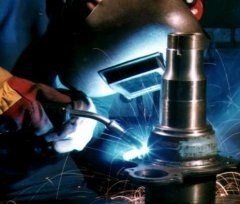
MIG Welding Device
0 notes
Text
METAL INERT GAS (MIG) WELDING
What is Metal Inert Gas (MIG) Welding?
Metal Inert Gas (MIG) welding is a bend welding measure that utilizes a nonstop strong wire anode warmed and took care of into the weld pool from a welding firearm. The two base materials are softened together shaping a join. The firearm takes care of a protecting gas close by the anode shielding the weld pool from airborne foreign substances.
Metal Inert Gas (MIG) welding was first licensed in the USA in 1949 for welding aluminum. The circular segment and weld pool shaped utilizing an uncovered wire cathode was secured by helium gas, promptly accessible around then. From around 1952, the cycle got mainstream in the UK for welding aluminum utilizing argon as the protecting gas, and for carbon prepares utilizing CO2. CO2 and argon-CO2 combinations are known as metal dynamic gas (MAG) measures. MIG is an alluring option in contrast to MMA, offering high testimony rates and high profitability.
Cycle Characteristics
MIG/MAG welding is a flexible method appropriate for both slight sheet and thick area parts. A bend is struck between the finish of a wire cathode and the workpiece, softening the two of them to frame a weld pool. The wire fills in as both warmth source (by means of the curve at the wire tip) and filler metal for the welding joint. The wire is taken care of through a copper contact tube (contact tip) which behaviors welding current into the wire. The weld pool is shielded from the encompassing environment by a protecting gas took care of through a spout encompassing the wire. Protecting gas choice relies upon the material being welded and the application.
The wire is taken care of from a reel by an engine drive, and the welder moves the welding light along the joint line. Wires might be strong (straightforward drawn wires), or cored (composites framed from a metal sheath with a powdered transition or metal filling). Consumables are for the most part seriously evaluated contrasted and those for different cycles. The interaction offers high efficiency, as the wire is consistently taken care of.
Manual MIG/MAG welding is frequently alluded as a self-loader measure, as the wire feed rate and circular segment length are constrained by the force source, however the movement speed and wire position are under manual control. The cycle can likewise be motorized when all the interaction boundaries are not straightforwardly constrained by a welder, yet may in any case require manual change during welding. At the point when no manual mediation is required during welding, the interaction can be alluded to as programmed.
The cycle for the most part works with the wire decidedly charged and associated with a force source conveying a consistent voltage. Determination of wire width (ordinarily somewhere in the range of 0.6 and 1.6mm) and wire feed speed decide the welding current, as the consume off pace of the wire will frame a balance with the feed speed.
Metal Transfer Mode
The way, or mode, in which the metal exchanges from the cathode to the weld pool to a great extent decides the working highlights of the interaction. There are three chief metal exchange modes:
Shortcircuiting/Dip
Bead/splash
Beat
Shortcircuiting and beat metal exchange are utilized for low current activity while splash metal exchange is just utilized with high welding flows. In shortcircuiting or 'plunge' move, the liquid metal shaping on the tip of the wire is moved by the wire dunking into the weld pool.

This is accomplished by setting a low voltage; for a 1.2mm distance across wire, circular segment voltage changes from about 17V (100A) to 22V (200A). Care in setting the voltage and the inductance corresponding to the wire feed speed is fundamental to limit splash. Inductance is utilized to control the flood in current which happens when the wire plunges into the weld pool.
For drop or shower move, a lot higher voltage is important to guarantee that the wire doesn't make contact for example hamper, the weld pool; for a 1.2mm distance across wire, the bend voltage fluctuates from roughly 27V (250A) to 35V (400A). The liquid metal at the tip of the wire moves to the weld pool as a splash of little drops (about the measurement of the wire and more modest). Nonetheless, there is a base current level, edge, beneath which drops are not persuasively projected across the circular segment.
On the off chance that an open circular segment procedure is endeavored much underneath the edge current level, the low curve powers would be lacking to forestall enormous drops framing at the tip of the wire. These drops would move inconsistently across the circular segment under typical gravitational powers. The beat mode was created as a methods for settling the open circular segment at low current levels for example beneath the limit level, to abstain from shortcircuiting and scatter.
Metal exchange is accomplished by applying beats of current, each heartbeat having adequate power to withdraw a drop. Synergic beat MIG alludes to a unique kind of regulator which empowers the force source to be tuned (beat boundaries) for the wire creation and measurement, and the beat recurrence to be set by the wire feed speed.
Protecting Gas
Notwithstanding broad protecting of the circular segment and the weld pool, the protecting gas plays out various significant capacities:
structures the circular segment plasma
settles the curve roots on the material surface
guarantees smooth exchange of liquid beads from the wire to the weld pool
In this manner, the protecting gas will substantially affect the security of the curve and metal exchange and the conduct of the weld pool, specifically, its entrance. Broadly useful protecting gases for MIG welding are combinations of argon, oxygen and CO2, and exceptional gas blends may contain helium. The gases which are regularly utilized for the different materials are:
Prepares:
CO2
argon +2 to 5% oxygen
argon +5 to 25% CO2
Non-ferrous (for example Aluminum, copper or nickel compounds):
argon
argon/helium
Argon based gases, contrasted and CO2, are by and large more open minded to boundary settings and create lower scatter levels with the plunge move mode. Notwithstanding, there is a more serious danger of absence of combination absconds in light of the fact that these gases are colder. As CO2 can't be utilized in the open bend (beat or shower move) modes because of high back-plasma powers, argon based gases containing oxygen or CO2 are ordinarily utilized.
Applications
MIG/MAG is broadly utilized in most industry areas and records for over half of all weld metal kept. Contrasted with MMA, MIG/MAG has the benefit as far as adaptability, affidavit rates and reasonableness for automation. Notwithstanding, it ought to be noticed that while MIG/MAG is ideal for 'spurting' metal, a serious level of manipulative expertise is requested of the MIG welder.
0 notes
Text
Advantages & Disadvantages Of Arc Welding
Advantages
SMAW or Stick Welding requires fundamental gear and fits field work since it is very convenient.
Cost is 30% to half of other welding strategies
Lightweight gear
Numerous kinds of accessible terminals
Great in restricted spaces
Cleaning metal surface prior to welding not as thorough as different strategies like TIG
Disadvantages
Need to eliminate slag in the wake of welding. Capture of slag likewise is an issue in SMAW framing incorporations, which should be eliminated.
Unused cathode hits – need to quit welding when you arrive at the last 2 crawls of the terminal
Splash
Moderate relative speed of SMAW.
Splash cleanup and slag evacuation work escalated
Makes a greater number of flashes and warmth than other welding strategies
Chipping and granulating finished welds gives us destructive residue
Need to quit during the welding cycle to supplant utilized cathode and to chip away slag
Splash and unused cathode hits represent approx. 44% of devoured anodes.
0 notes
Text
Submerged Arc Welding (SAW)
Lowered bend welding (SAW) is a cycle wherein the joining of metals is created by warming with a circular segment or curves between an uncovered metal cathode or anodes and the work.
The bend is protected by a cover of granular fusible material on the work.
Pressing factor isn't utilized.
Filler metal is gotten from the terminal or from a strengthening welding bar.
Curve Welding Demonstration
Gear
The SAW gear parts needed for lowered curve welding are appeared by figure 10-59.
Hardware comprises of a welding machine or force source, the wire feeder and control framework, the welding light for programmed welding or the welding firearm and link gathering for self-loader welding, the motion container and taking care of instrument, typically a transition recuperation framework, and a movement system for programmed welding.
The force hotspot for lowered circular segment welding should be appraised for a 100% obligation cycle, since the lowered curve welding activities are ceaseless and the time allotment for making a weld may surpass 10 minutes.
On the off chance that a 60 percent obligation cycle power source is utilized, it should be derated by the obligation cycle bend for 100% activity.
At the point when steady current is utilized, either ac or dc, the voltage detecting anode wire feeder framework should be utilized.
At the point when consistent voltage is utilized, the more straightforward fixed speed wire feeder framework is utilized. The CV framework is just utilized with direct current.
Both generator and transformer-rectifier power sources are utilized, however the rectifier machines are more mainstream.
Welding machines for lowered bend welding range in size from 300 amperes to 1500 amperes.
They might be associated in corresponding to give additional capacity to high-current applications.
Direct current force is utilized for self-loader applications, however substituting current force is utilized principally with the machine or the programmed technique.
Different cathode frameworks require particular kinds of circuits, particularly when ac is utilized.
SAW Equipment
Appeared: SAW or lowered curve welding hardware finishing a weld. The weld begins the privilege and moves left. The dark hued powder is transition
For self-loader application, a welding firearm and link get together are utilized to convey the anode and current and to give the transition at the circular segment.
A little motion container is joined to the furthest limit of the link get together.
The terminal wire is taken care of through the lower part of this motion container through a current pickup tip to the bend.
The motion is taken care of from the container to the welding zone by methods for gravity.
The measure of transition took care of relies upon how high the firearm is held over the work.
The container firearm may incorporate a beginning change to start the weld or it might use a "hot" cathode with the goal that when the anode is contacted to the work, taking care of will start consequently.
For programmed welding, the light is appended to the wire feed engine and incorporates current pickup tips for sending the welding current to the anode wire.
The motion container is regularly appended to the light, and may have attractively worked valves which can be opened or shut by the control framework.
Different bits of gear here and there utilized may incorporate a movement carriage, which can be a straightforward farm truck or a complex moving particular installation. A transition recuperation unit is typically given to gather the unused lowered curve motion and return it to the inventory container.
Lowered circular segment welding framework can turn out to be very intricate by consolidating extra gadgets, for example, crease devotees, weavers, and work wanderers.
SAW Welding Diagram
lowered bend welding graph
Figure 10-59. Square graph of SAW (lowered bend welding) Equipment.
Benefits Of SAW
The significant benefits of the SAW or lowered bend welding measure are:
great metal weld.
incredibly fast and testimony rate
smooth, uniform completed weld with no scatter.
next to zero smoke.
no curve streak, along these lines insignificant requirement for defensive apparel.
high use of cathode wire.
simple mechanization for high-administrator factor.
typically, no association of manipulative abilities.
SAW welding cycle to assemble long steel heaps to help sea stage.
Significant Uses Of SAW
The lowered circular segment measure is broadly utilized in weighty steel plate creation work. This incorporates the welding of:
underlying shapes
the longitudinal crease of bigger distance across pipe
the production of machine segments for a wide range of substantial industry,
the production of vessels and tanks for pressing factor and capacity use
It is broadly utilized in the shipbuilding business for joining and creating sub-gatherings, and by numerous different ventures where prepares are utilized in medium to substantial thicknesses.
It is likewise utilized for surfacing and development work, upkeep, and fix.
In SAW welding the transition and wire are independent. Both effect the properties of the weld, requiring the determination of the ideal mix by the architect for each undertaking.
Interaction Limitations
A significant impediment of SAW (lowered circular segment welding) is its limit of welding positions. The other constraint is that it is basically utilized uniquely to weld gentle and low-composite high-strength prepares.
The high-heat input and moderate cooling cycle can be a difficult when welding extinguished and tempered prepares. The warmth input restriction of the steel being referred to should be carefully clung to when utilizing lowered bend welding.
This may require the creation of multipass welds where a solitary pass weld would be adequate in gentle steel. At times, the financial benefits might be diminished to where motion cored curve welding or some other cycle ought to be thought of.
In self-loader lowered circular segment welding, the failure to see the bend and puddle can be a drawback in arriving at the foundation of a score weld and appropriately filling or measuring.
Show of Saw Welding Process.
Standards Of Operation
Cycle
The lowered curve welding measure is appeared by figure 10-60. It uses the warmth of a circular segment between a consistently taken care of terminal and the work.
Figure 10-60: Process Diagram for SAW (lowered circular segment welding)
The warmth of the circular segment dissolves the outside of the base metal and the finish of the cathode. The metal liquefied off the cathode is moved through the circular segment to the workpiece, where it turns into the saved weld metal.
Protecting is gotten from a cover of granular transition, which is laid straightforwardly over the weld zone. The motion near the circular segment softens and intermixes with the liquid weld metal, assisting with cleansing and sustain it.
The motion frames a glass-like slag that is lighter in weight than the kept weld metal and buoys on a superficial level as a defensive cover.
The weld is lowered under this layer of transition and slag, subsequently the name lowered bend welding. The motion and slag regularly cover the curve so it isn't noticeable.
The unmelted segment of the motion can be reused. The cathode is taken care of into the circular segment naturally from a curl. The bend is looked after naturally.
Travel can be manual or by machine. The curve is started by a breaker type start or by a switching or retrack framework.
Ordinary Method Of Application And Position Capabilities
The most mainstream technique for SAW application is the machine strategy, where the administrator screens the welding activity.
Second in prevalence is the programmed technique, where welding is a pushbutton activity. The interaction can be applied semiautomatically; notwithstanding, this technique for application isn't excessively famous.
The interaction can't be applied physically in light of the fact that it is unthinkable for a welder to control a curve that isn't noticeable. The lowered bend welding measure is a restricted position welding measure.
The welding positions are restricted on the grounds that the huge pool of liquid metal and the slag are exceptionally liquid and will in general run out of the joint. Welding should be possible in the level position and in the flat filet position easily.
Under extraordinary controlled methodology, it is conceivable to weld in the level position, here and there called 3 o'clock welding.
This requires exceptional gadgets to hold the motion up with the goal that the liquid slag and weld metal can't flee. The interaction can't be utilized in the vertical or overhead position.
Metals Weldable And Thickness Range
Lowered circular segment welding is utilized to weld low-and medium-carbon prepares, low-compound high-strength prepares, extinguished and tempered prepares, and numerous treated steels.
Tentatively, it has been utilized to weld certain copper composites, nickel compounds, and even uranium.
Metal thicknesses from 1/16 to 1/2 in. (1.6 to 12.7 mm) can be welded with no edge readiness. With edge readiness, welds can be made with a solitary pass on material from 1/4 to 1 in. (6.4 to 25.4 mm).
At the point when the multipass procedure is utilized, the greatest thickness is for all intents and purposes limitless. This data is summed up in table 10-22. Even filet welds can be made up to 3/8 in. (9.5 mm) in a solitary pass and in the level position, filet welds can be made up to 1 in. (25 mm) size.
Joint Design
Albeit the lowered bend welding interaction can use a similar joint plan subtleties as the protected metal circular segment welding measure, distinctive joint subtleties are proposed for most extreme use and effectiveness of lowered curve welding. For groove welds, the square furrow configuration can be utilized around 5/8 in. (16 mm) thickness.
Past this thickness, slopes are required. Open roots are utilized yet backing bars are fundamental since the liquid metal will go through the joint.
When welding thicker metal, if an adequately enormous root face is utilized, the sponsorship bar might be killed. Be that as it may, to guarantee full infiltration when welding from one side, backing bars are suggested. Where the two sides are available, a support weld can be made which will intertwine into the first weld to give full entrance.
Welding Circuit And Current
The SAW or lowered circular segment welding measure utilizes either immediate or exchanging current for welding power. Direct current is utilized for most applications that utilization a solitary bend. Both direct current anode positive (DCEP) and elec
0 notes
Text
MIG Welding (GMAW) Process Techniques & Tips
Gas metal bend welding (GMAW), some of the time alluded to by its subtypes, metal latent gas (MIG) welding or metal dynamic gas (MAG) welding, is a self-loader or programmed circular segment welding measure in which a constant and consumable wire terminal and a protecting gas are taken care of through a welding firearm.
A steady voltage, direct current force source is most regularly utilized with GMAW, yet consistent current frameworks, too as substituting current, can be utilized.
There are four essential techniques for metal exchange in GMAW:
Globular
Shortcircuiting
Splash
Beat shower
Every one of which has unmistakable properties and comparing benefits and constraints.
Protecting is acquired from a remotely provided gas or gas blend.
History
Initially produced for welding aluminum and other non-ferrous materials during the 1940s, GMAW was before long applied to prepares in light of the fact that it took into account lower welding time contrasted with other welding measures.
The expense of latent gas restricted its utilization in prepares until quite a long while later, when the utilization of semi-dormant gases, for example, carbon dioxide got normal.
Initially created for welding aluminum and other non-ferrous materials during the 1940s, GMAW was before long applied to prepares on the grounds that it took into consideration lower welding time contrasted with other welding measures.
The expense of idle gas restricted its utilization in prepares until quite a while later, when the utilization of semi-inactive gases, for example, carbon dioxide got normal.
MIG Welding Basics
MIG welding is worked in self-loader, machine, and programmed modes. It is used especially in high creation welding tasks.
All monetarily significant metals, for example, carbon steel, treated steel, aluminum, and copper can be welded with this interaction taking all things together situations by picking the suitable protecting gas, terminal, and welding conditions.
Hardware
Gas metal bend welding hardware comprises of a welding firearm, a force supply, a protecting gas supply, and a wire-drive framework that pulls the wire anode from a spool and pushes it through a welding weapon.
A wellspring of cooling water might be needed for the welding weapon.
In going through the firearm, the wire gets invigorated by contact with a copper contact tube, which moves current from a force source to the bend.
While straightforward on a basic level, an arrangement of exact controls is utilized to start and end the protecting gas and cooling water, work the welding worker for hire, and control terminal feed speed as required.
The essential highlights of MIG welding hardware are appeared in figure 10-45.
The MIG cycle is utilized for self-loader, machine, and programmed welding. Self-loader MIG welding is regularly alluded to as manual welding.
Advancements during the 1950s and 1960s gave the interaction greater flexibility and subsequently, it turned into an exceptionally utilized modern cycle.
Today with the absolute best MIG machines around, GMAW is generally utilized in ventures like the vehicle business, where it is liked for its adaptability and speed.
Dissimilar to welding measures that don't utilize a protecting gas, for example, protected metal curve welding, it is seldom utilized outside or in different regions of air instability.
A connected Mig measure, motion cored circular segment welding, frequently doesn't use a protecting gas, rather utilizing an empty terminal wire that is loaded up with transition within.
Force Supply
Two kinds of force sources are utilized for MIG welding: consistent current and steady voltage.
1. Consistent Current Power Supply
With this kind, the welding current is set up by the proper setting on the force supply.
Bend length (voltage) is constrained by the programmed change of the terminal feed rate.
This kind of welding is most appropriate to huge measurement anodes and machine or programmed welding, where fast difference in terminal feed rate isn't needed.
Most steady current force sources have a hanging volt-ampere yield trademark.
Nonetheless, genuine consistent current machines are accessible.
Steady current force sources are not regularly chosen for MIG welding as a result of the control required for cathode feed speed. The frameworks are not automatic.
2. Steady Voltage Power Supply
The curve voltage is set up by setting the yield voltage on the force supply.
The force source will supply the fundamental amperage to liquefy the welding cathode at the rate needed to keep up the current voltage or relative curve length.
The speed of the terminal drive is utilized to control the normal welding current.
This trademark is by and large liked for the welding, all things considered.
The utilization of this sort of force supply related to a consistent wire anode feed brings about a self-adjusting circular segment length framework.
Engine generator or dc rectifier power wellsprings of either type might be utilized.
With a beat direct current force supply, the force source beats the dc yield from a low foundation incentive to a high pinnacle esteem.
Since the normal force is lower, beat welding current can be utilized to weld more slender segments than those that are functional with consistent dc shower move.
Manual And Automatic Welding Guns
Welding firearms for MIG welding are accessible for manual control (self-loader welding) and for machine or programmed welding.
Since the cathode is taken care of persistently, a welding firearm should have a sliding electrical contact to communicate the welding flow to the terminal.
The weapon should likewise have a gas entry and a spout to coordinate the protecting gas around the circular segment and the liquid weld pool.
Cooling is needed to eliminate the warmth produced inside the firearm and transmitted from the welding curve and the liquid weld metal.
Protecting gas, inward circling water, or both, are utilized for cooling.
An electrical switch is expected to begin and stop the welding flow, the cathode feed framework, and protecting gas stream.
Self-loader MIG Welding Guns
Self-loader, hand-held weapons are generally like a gun fit as a fiddle.
Now and again they are molded like an oxyacetylene light, with cathode wire took care of through the barrel or handle.
In certain adaptations of the gun plan, where the most cooling is essential, water is guided through sections in the weapon to cool both the contact tube and the metal protecting gas spout.
The bended weapon utilizes a bended current-conveying body at the front end, through which the protecting gas is brought to the spout.
This sort of firearm is intended for little width wires and is adaptable and flexibility.
It is appropriate for welding in close, difficult to arrive at corners and other restricted spots. Weapons are outfitted with metal spouts of different interior widths to guarantee satisfactory gas protecting.
The hole ordinarily changes from roughly 3/8 to 7/8 in. (10 to 22 mm), contingent on welding necessities.
The spouts are normally strung to make substitution simpler.
The traditional gun type holder is likewise utilized for curve spot welding applications where filler metal is required.
The substantial spout of the holder is opened to deplete the gases from the spot.
The single handed grip handle allows simple manual stacking of the holder against the work.
The welding control is intended to manage the progression of cooling water and the stock of protecting gas.
It is additionally intended to forestall the wire sticking to the weld by timing the weld over a preset span.
A common self-loader gas-cooled firearm is appeared in figure 10-46.
Air Cooled Guns
Air-cooled weapons are accessible for applications where water isn't promptly reachable as a cooling medium. These firearms are accessible for administration up to 600 amperes, discontinuous obligation, with carbon dioxide protecting gas. Notwithstanding, they are normally restricted to 200 amperes with argon or helium protecting. The holder is by and large gun like and its activity is like the water-cooled type. Three general sorts of air-cooled weapons are accessible.
A weapon that has the anode wire took care of to it through an adaptable channel from a distant wire taking care of system. The channel is by and large in the 12 ft (3.7 m) length range because of the wire taking care of constraints of a push-type framework. Steel wires of 7/20 to 15/16 in. (8.9 to 23.8 mm) width and aluminum wires of 3/64 to 1/8 in. (1.19 to 3.18 mm) measurement can be taken care of with this game plan.
A weapon that has an independent wire feed component and terminal wire supply. The wire supply is for the most part as a 4 in. (102 mm) measurement, 1 to 2-1/2 lb (0.45 to 1.1 kg) spool. This sort of firearm utilizes a draw type wire feed framework, and it isn't restricted by a 12 ft (3.7 m) adaptable conductor. Wire breadths of 3/10 to 15/32 in. (7.6 to 11.9 mm) are typically utilized with this kind of weapon.
A draw type firearm that has the anode wire took care of to it through an adaptable channel from a far off spool. This joins an independent wire taking care of system. It can likewise be utilized in a push-pull type taking care of framework. The framework allows the utilization of adaptable conductors in lengths up to 50 ft (15 m) or more from the distant wire feeder. Aluminum and steel cathodes with distances across of 3/10 to 5/8 in. (7.6 to 15.9 mm) can be utilized with these kinds of feed instruments.
Water-Cooled Guns
Water-cooled firearms for manual MIG welding like gas-cooled types with the expansion of water cooling pipes. The channels flow water around the contact tube and the gas spout. Water cooling grants the firearm to work ceaselessly at appraised limit and at lower temperatures.
Water-coded firearms are utilized for applications requiring 200 to 750 amperes. The water in and out lines to the firearm add weight and decrease mobility of the weapon for welding.
Air Vs. Water Cooled Welding Guns
The choice of air-or water-cooled weapons depends on the kind of protecting gas, welding ebb and flow range, materials, weld joint plan, and existing shop practice. Air-cooled firearms are heavier than water-cooled weapons of a similar welding momentum limit. Be that as it may, air-cooled weapons are simpler to control to weld out-o
1 note
·
View note