
Don't wanna be here? Send us removal request.
Statistics
We looked inside some of the posts by proceduralcaves and here's what we found interesting.
Average Info
Notes Per Post
0
Likes Per Post
0
Reblog Per Post
0
Reply Per Post
0
Time Between Posts
2 days
Number of Posts By Type
Text
17
Last Seen Tumblr Blogs


Fun Fact
Post activity is at the highest at 4:00 pm EDT; notes peak at 10:00 pm EDT.
Text
Dual Contouring background
Dual Contouring, like Marching Cubes, is an isosurface extraction algorithm, but instead of placing vertices on cube edges it creates a single new vertex inside each cube that contains corners both inside and outside of the surface (determined by testing against a threshold value, in the same way as Marching Cubes). Those vertices are then used as the corners of quads formed with adjacent cubes.
In order to determine the placement of new vertices, more information about the cube corner values is required. Dual Contouring needs to calculate how quickly the values of cube corner points change when moving in a given direction, i.e. it is required to compute their gradients. The same vertex intersection positions as in Marching Cubes are calculated along with their gradients, which are then used to represent normal vectors. The vertex position that is chosen is that which lies on the plane identified by the previously calculated normal vectors. The same process is performed for each cube, before connecting the planes to form a mesh.
However, a complication arises when the gradient values lead to normals that no single flat plane can be created from, due to the inconsistent directions they point in. In these cases it is required to find a point that is overall the closest distance to the planes of all normals, which is found through use of a quadratic error function. Yet, that does not fully solve the problem because it is not guaranteed that the closest point will be inside the cube being processed. The method of dealing with said problem and the implementation of the quadratic error function are detailed in section <link to QEF section in Methodology>.
The algorithm was introduced in 2002 and has the advantage over Marching Cubes of being able to represent sharp features like edges and corners. It also does not require a lookup table of polygon configurations. Due to it also operating on a grid/scalar field, it can be applied to similar problems as other isosurface extraction algorithms.
It was chosen as an algorithm for the cave generation method due to the attribute of feature preservation as well to provide a point of comparison against Marching Cubes regarding performance and complexity of implementation.
0 notes
Text
Marching Cubes 33 background
Marching Cubes algorithms are used for creating (sometimes referred to as "extracting") a three-dimensional polygon mesh from a grid of three-dimensional coordinates with corresponding values (also known as a three-dimensional scalar field). They serve as methods for constructing geometric surfaces from numerical data (such as volumetric datasets obtained from MRI scans) (Polygonising a scalar field (Marching Cubes) (paulbourke.net)). By dividing a three-dimensional grid into cubes, polygon arrangements can be created within each cube (by attaching vertices to cube edges) to 'isolate' some corners of each cube from others within the same cube. The set of corners chosen to be isolated and the edge points for polygon vertex attachment depend upon the values of cube corner points, with the specific values originating from the dataset or function initially used to create the original grid/scalar field. Polygon arrangements are precalculated — there are a set number of configurations (14 unique cases and 256 in total with symmetries in the original algorithm) for isolating different groupings of corners — and stored in a lookup table which is accessed when processing each cube in the grid. Once every cube has been processed, the polygons that have been created form a mesh.
The original Marching Cubes algorithm was created in 1984 by two scientists working in research and development for General Electric — William Lorensen (Computer Systems and Services department) and Harvey Cline (Electronic Materials Lab department) — who were inspired to work on the problem after attending a seminar about a (not yet built) rendering engine envisioned as being applicable to the task of three-dimensional medical surface display. The seminar speaker challenged the attendees to think of a solution for replacing a cuberille-based technology (representing three-dimensional pixels as cubes) with a polygon-based one. The Marching Cubes solution was formulated by Lorensen and Cline after the seminar on the same day, with Lorensen able to implement a working algorithm by the following day (History of the Marching Cubes Algorithm (computer.org)).
In 1991, ambiguities in the original algorithm were identified (The asymptotic decider: resolving the ambiguity in marching cubes | IEEE Conference Publication | IEEE Xplore). Those ambiguities being:
Certain pairs of polygon configurations may result in small holes in the mesh on shared faces of neighbouring cubes.
There can be more than one polygon configuration that isolates the same corners and the configuration that results in a hole-free mesh cannot be known without checking the configurations of cubes that share faces with the cube currently being processed.
(Chernyaev, 1995) proposed a new algorithm, Marching Cubes 33, that increases the number of topologically distinct polygon configurations from 15 to 33, and introduces new test cases for when to use each configuration, resolving the ambiguities (although only partially). Lewiner, 2003 completed and enhanced the method by Chernayaev and implemented a C++ solution that utilises a complete lookup table based on the configurations in the original Marching Cubes 33 paper. It is the implementation by Lewiner that forms the basis of the algorithm used in the novel method that has been developed.
0 notes
Text
Cellular automata background
Cellular automata algorithms are used to determine the behaviour of regular grids of cells (in any number of dimensions), where each cell can be in one of a finite number of states. The grid is updated in discrete timesteps, changing the states of cells based on the states of neighbouring cells, with different rules able to be specified to control whether the state of a cell increases or decreases (with the lowest state often meaning a cell is off/dead).
During the 1940's, in the process of attempting to gain insight into biological evolution and self-reproduction, the concept of cellular automata was developed and then described by mathematician and computer scientist John von Neumann in a 1948 paper (von Neumann, ‘The General and Logical Theory of Automata’.) (it was suggested to him by a colleague, Stanislaw Ulam, to use a cell-based concept to solve the problem of how a machine could self-reproduce). (John von Neumann's Cellular Automata | Embryo Project Encyclopedia (asu.edu)).
The concept became more widely known when mathematician John Conway invented the "Game of Life" — a two-dimensional cellular automaton where each cell can have one of two states, capable of producing diverse behaviour — and it was subsequently written about in a popular science magazine (The Lasting Lessons of John Conway’s Game of Life - The New York Times (nytimes.com)).
Modern applications of cellular automata include biology (Cellular Automata as Microscopic Models of Cell Migration in Heterogeneous Environments - ScienceDirect (abertay.ac.uk)), cryptography (https://www.mecs-press.org/ijcnis/ijcnis-v9-n12/IJCNIS-V9-N12-6.pdf) and computer graphics. An implementation of a cellular automata algorithm has been used in previous work to generate two-dimensional cave environments in the area of computer games (Johnson2010Cellular.pdf (togelius.com)). The novel method being developed as part of the research undertaken was inspired by the work of Sebastian Lague ([Unity] Procedural Cave Generation (E01. Cellular Automata) - YouTube) combining a two-dimensional cellular automaton with a Marching Cubes algorithm to create a three-dimensional cave-like environment.
0 notes
Text
Source notes: Synthesizing Geologically Coherent Cave Networks
(Paris et al., 2021)
Type: Journal Article
Method
Geologically-based method for generating karstic cave networks. Karsts are a type landscape formed by dissolution of highly soluble rocks (generally limestone).
Method works by computing skeletons of networks using a gridless anisotropic shortest path algorithm according to field data of an underground system, and other geomorphological features and parameters (faults, fractures etc.).
That skeleton is then used to define geometry by blending and warping geometric primitives using a construction tree approach.
Method exists within a framework that provides extensive control over the generated model, allowing users to "define inlets, outlets, and waypoints as passages to constrain the construction of the karstic network, prescribe the different volumetric geological parameters, and adjust the paths of the tunnels inside the bedrock.

Strengths
User control combined with automatic generation.
Focus on realism and geological research.
Able to create large-scale networks (spanning over several kilometers) varying in structures and complexity.
Limitations
Lack of detail in paper on rendering and visual enhancements that are visible in images — texturing, rough geometry of walls.
No stalactites or stalagmites.
The fact the method is based on geological models may be restrictive when structural realism is not a priority; in a games development setting variation and flexibility may be more desirable.
0 notes
Text
Source notes: Procedural Modeling of Cave-like Channels
(Pytel and Mann, 2015)
Type: Journal Article
Simulation of hydraulic erosion uses flow and pressure to reproduce 3D cave-like channels.
Aim is to model extensive systems, rather than smaller scale features like speleothems.
Simulation takes place in a voxel grid, with each voxel representing a unit of rock with a value representing porosity.
Polygonization of the appropriate voxels takes place when a simulated erosion process increases porosity of voxels inside channels.
A protochannel stage begins the process by creating initial channels that begin at voxels used to contain sources of flow.
A channel growth and linkage stage simulates a flow from source voxels to "sin" voxels by way of a self-organised formulation that encapsulates how pressure is affected by erosion, how flow changes based on pressure and how flow contributes to erosion.
The method is also able to simulate tributaries.
A fast marching algorithm, simulating propagation of a front through a grid, is used to begin the protochannel stage.
A network flow algorithm (used to compute maximum flow in a network subject to capacity constraints) is then implemented to simulate continued flow through the protochannels.
The fast marching algorithm is again used for the channel growth and linkage stage, and a simulation algorithm where each voxel distributes water to its neighbours based on pressure difference and remaining capacity. Erosion and flow are further simulated based on a simplified terrain hydraulic erosion model and a water-column algorithm.
A slope texturing technique was used for rendering and composited based on masks generated using Perlin noise.

Strengths
Geologically-based.
Extensive networks created, with intricate paths and connections.
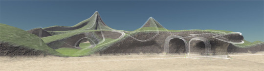
Naturally creates tunnels and arches, as well as other convincingly realistic structural features.
Vegetation implemented in the form of slope texturing (although without an apparent sun source).
Raised platforms and walkways seem to be automatically generated by the method.
Limitations
Unclear how much control over the method is possible via parameterisation or modification of input data.
No stalagmites or stalactites.
Cave wall surface appears uncharacteristically smooth.
0 notes
Text
Source notes: Arches: a Framework for Modeling Complex Terrains
(Peytavie et al., 2009)
Type: Journal Article
Keywords: Three-Dimensional Graphics, Realism
(Peytavie et al., 2009) add to the literature by constructing a framework for modelling terrains that feature overhangs, arches and caves. The framework combines a volumetric data structure used to store different materials and a method for sculpting and reconstructing (delivered as interactive tools) the terrain surface. In addition, the authors developed a technique to generate loose rocks to add to the terrain-based environments.
Method
A discrete volumetric data structure stores layers of materials that compose the terrain and two representations of the terrain model.
One model is called "implicit" and serves as the representation used when sculpting and generating the terrain mesh (via surface polygonization algorithms).
The other is "discrete", containing material layers that is used when invoking a post-processing step to ensure sand and rock layers stabilise after each sculpting or editing step.
The method defines terrains as two-dimensional grids of material stacks (materials vary by thickness and type with air, water, sand, bedrock and rocks all supported).
Algorithms for sculpting bedrock layers and adding layers of different materials are utilised by high-level tools that enable manual editing of the terrain. Sculpting can be performed by "deforming and carving the terrain in the direction of the normal to the surface" or by executing algorithms to specifically create cracks or networks of tunnels (developed because such large-scale sculpting and editing work is time-consuming and repetitive).
Another tool, defined as a brush described by a depositing region, was developed for depositing granular material layers such as sand onto existing terrain.
The authors developed a new erosion technique to simulate rocks detaching from a terrain and forming piles on the ground. It works by way of a designer defining a tool with a region of influence and a parameter that controls how much material it erodes. The tool is then swept over the surface of the terrain to either transform bedrock into sand or completely detach rocks that then fall into the scene (simulating the case where bedrock is cracked along internal joints).
Rock piles can be generated in place (not physics or collision based, instead using precomputed contact points) using a Voronoi diagram technique. A cubic tile containing Voronoi cells representing rocks is created, erosion is then simulated by creating triangles between contact points of cells (chosen randomly on each edge). Rock models are then instantiated within the cubic tile.
Texture blending is used when rendering, with each material in the stack having its texture blended according to the ratio of neighbouring materials.

Strengths
Lots of features, able to create caves, overhangs, rock piles, and more depending on what designers do with the tools.
High level of realism with multiple materials and texture blending.
Tools for automatically creating tunnel networks, resulting in realistic cave systems.
Framework could be extended to develop tools for more automated creation of speleothems.
Interactive editing tools provide granular level of control.
High degree of expressivity (limited largely by the time, effort and skill of designers).
Limitations
No direct discussion of stalagmites and stalactites, although they can be seen in one of the images, and based on the other features created via sculpting and editing, would be trivial to create.
Manual effort required and skill of a designer to create effective results.
0 notes
Text
Source notes: Procedural Playable Cave Systems based on Voronoi Diagram and Delaunay Triangulation
(A. Santamaría-Ibirika et al., 2014)
Type: Conference Paper
Keywords: procedural terrain, procedural caves, volumetric terrain
The authors address the issue of generating cave systems with playable features and a natural appearance. A new method is proposed for both 2D and 3D volumetric terrains, based on Voronoi diagrams and Delaunay triangulations. Customisation is enable via parameters that link directly to the properties of the output, obviating the need for technical expertise of operators.
Method
Based on a system of "points of interest" (POI), where designers define points by their depth and relationships to other POIs.
Underground "galleries" are constructed from the relationships between POIs.
Transparent input parameters.
Completely autonomous execution, requiring no user interaction once generation is triggered.
Intended to look realistic.
Voronoi diagrams — a method of partitioning space into regions based on a set of points (called seeds). A plane or space of coordinates has a subset of points that are chosen as seeds. For each seed a region is created containing all of the points closest to it. Boundaries between regions are created where points are equidistant to seeds.
Delaunay triangulations — by connecting the seed points that share region edges in the Voronoi diagram, a Delaunay triangulation is created. This process can be done in reverse to obtain the Voronoi diagram from a Delaunay triangulation by connecting the centres of the triangle circumcircles to create the edges in the diagram. For all triangles created by a Delaunay triangulation, no vertex lies within the circumcircle of any other triangle. Delaunay triangulations maximise the minimum angle of all triangles, which means the number of thin triangles is reduced.
Input data is specified by a human designer who must create a set of POIs, defining such parameters as their name, location (inside terrain or on surface), depth (in relation to the terrain depth), cavity size (important for creating caves) and branches.
Next, relationships between POIs must be created, defining such characteristics as the degree of connectedness of POIs to others, and the distance between them.
Lastly, global parameters are determined. Most of the POI parameters calculate their final values based on global parameters (i.e. they are relative), and so absolute values are required for the overall terrain such as depth, global cavity size and sinuosity.
In terms of execution, the process starts by generating the Voronoi diagram and Delaunay triangulation. Seeds are chosen as random points uniformly distributed over the terrain, the amount of which is decided by an equation with the size of the terrain and global cavity size as variables.
Next, the first POI is chosen along with a Voronoi region to locate it. Caves are then mapped out by iterating through POIs, forming galleries between them based on the POI and POI relationship data previously defined, selecting and traversing cells of the Voronoi diagram in the process.
A volumetric terrain representation method, as is detailed in the authors' previous work (Santamaría-Ibirika et al., 2014), is used to physically generate the caves. The method is capable of generating several caves within the same terrain volume.

Strengths
The input data system is fairly intuitive to understand yet provides a large degree of design control over the generated environments, making it more likely it would be a successful game development tool. It is capable of creating varied cave shapes and tunnels with a realistic structure.
Limitations
From the images in the document, it appears the final model is still in unsmoothed voxel form, which decreases the realistic quality of the generated models. The method as it is proposed has no support for generating speleothems, organic matter or loose objects. Texturing and other visual enhancements enabled by shader programming may have helped to make the results more recognisably cave-like.
0 notes
Text
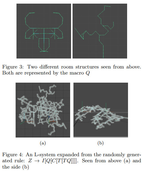
Source notes: Procedural Generation of Underground Systems with Terrain Features using Schematic Maps and L-systems
(Antoniuk and Rokita, 2016)
Type: Journal Article
Priorities
Emphasis on control and parameterisation over final layout.
Various terrain features.
Targeting computer games.
Method
Implemented in Blender.
Input is in the form of three types of 2D maps made up of tiles — one to define the type of terrain in each tile, a second to define the heights of tiles, a third to define connections inside each level and a fourth to define connections between levels. Each level consists of a set of tiles containing one of each type of map.
L-system used for cave shape generation with each new direction being chosen randomly.
Cellular automata used to fill shape and extend it.
First stage is to process terrain type map. Data from that map determines the number of iterations in that region of the terrain for the cellular automata and L-system processes, with high iterations resulting in large spaces and lowest in passages.
Connections between tiles are then checked, connecting neighbouring tiles.
The cellular automata algorithm is applied to "fill and extend spaces inside tile". The exact details of this implementation are not covered.
Paths created by the L-system and cellular automata algorithms are then joined together to ensure all areas are accessible.
A smoothing process is then applied.
Output is 2D tile maps with white pixels representing empty space and black pixels vertices.
Those output maps are combined with the height maps to create 3D models in Blender (creating vertices from the black pixels with heights specified by the height maps). A user can then arrange each 3D tile before the connection tile maps are used to connect edges between tiles. The resulting 3D mesh is then textured with a simple material. Specific details on the implementation of the conversion of the black and white tile maps to the 3D mesh are not discussed.

Stalactites, stalagmites and columns can be placed at random points throughout the cave models. They are generated based on three properties — base diameter, tip diameter and number of vertices in base. This results in a large variety of shapes. Vertex displacement is used to form each speleothem.

Strengths
The tile map system provides a relatively intuitive method of controlling generation that can be highly specific, eliminating the unpredictability found in many procedural methods.
Three different speleothems were included and the technique used to create them results in a diverse array of shapes and size, making the resultant models appear more realistic.
Limitations
It is unclear from the provided images how the caves could be used as standalone assets within a computer game. There do not seem to be clear tunnels or cavities delineated by walls, floors and ceilings. The output is not instantly recognisable as a real-world cave.
Details are not given on how the input tile maps are created. Depending on this process and use case, it is debatable if it is an advantage over an input method that is simpler and less time consuming yet provides less fine-grained control. Furthermore, stochasticity in generation methods can be positive or negative depending on factors such as execution time, extent of use and art direction.
0 notes
Text
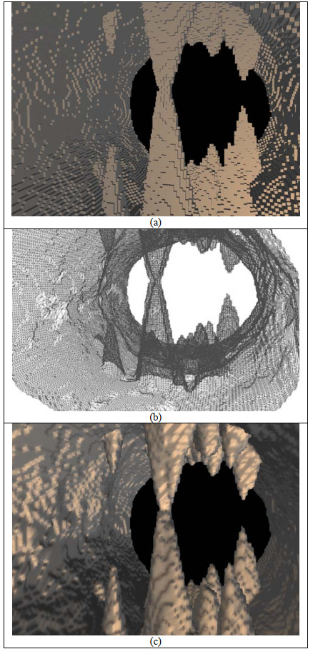
Source notes: Procedural generation of 3D karst caves with speleothems
(Franke and Müller, 2021)
Type: Journal Article
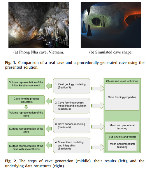
(Franke and Müller, 2021) develop a novel method for generating a specific type of real-world cave known as a karst cave (natural underground cavities formed in soluble rocks by slightly acidic water) including the recreation of passages, wall surfaces and speleothems. Realism of the generated models is prioritised, not through physical modelling and simulation but by focusing on reproducing explicit natural phenomena as documented in the field of speleology.
The method, like the Masters project, was implemented in the game engine Unity and the generated models can be traversed and visualised interactively. The stages are as follows: a geology model of a karst region is first developed, containing such information as the size of the region, and functions expressing the thickness and smoothness of rock layers and positioning of joints between layers. Said model is then represented as a regular grid of voxels which undergoes a simulated process of water flow and erosion (based on properties such as water flow velocity, acid concentration, and temperature deltas) to affect the density of the region which results in widened cavities, ultimately forming caves. Bother water flow and erosion simulations can be customised and iterated to create more intricate cave networks, as well as to increase the flexibility of the method. A polygonal representation is then extracted from the grid using the density values of the voxels, which are processed by the Marching Cubes algorithm. Perlin Noise is used to create a texture emulating oxides of copper and iron which are then combined (using linear interpolation) with a Worley Noise function based generated texture to create the appearance of a ridged surface with iron and copper colouring visible through cracks. Vertex displacement is used to displace mesh vertices to create a jagged surface (a similar technique is used in the Masters project). Stalactites and stalagmites are created based on an equation describing their shape (based on the radius) within their own voxel grid, with the mesh also being created from an isosurface, and are then placed slightly outside the cave grid (through the floor or ceiling) to prevent any part of the base of the speleothems from being visible (a point of detail that was taken into consideration for the Masters project method).
The method creates a realistic (in structure and relative to the other reviewed methods) extensive cave system by adhering to constraints chosen through observation and speleological modelling. Vadose and phreatic passages are emulated. Stalagmites and stalactites are included, being generated in realistic places and in pairs. Dripstone columns can also be recreated when a a stalagmite and stalactite mesh intersects. Features such as sinkholes and fractures can be created by the water flow simulation. In terms of controllability and parameterisation — the model, water and erosion simulation parameters can be altered to vary the model that is generated.
As the method prioritises real-world modelling there are necessarily limits to the types of cave systems it can generate. Emulation of natural phenomena may not always be required — a procedurally generated cave can still appear believable and visually plausible to users without specialised speleological knowledge. If the target use case is computer games it may be that properties such as playability, variety and immersion are more important and it is worth asking if those are negatively affected by prioritising realism.
0 notes
Text
Source notes: Procedural Generation of 3D Caves for Games on the GPU
(Mark et al., 2015)
Type: Conference Paper
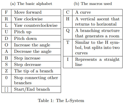
The researchers present a modular pipeline for procedurally generating believable (not physically-based) underground caves in real-time, intended to be used standalone or as part of larger computer game environments. Their approach runs mainly in the GPU and utilises the following techniques: an L-system to emulate cave passages found in nature; a noise-perturbed metaball for 3D carving; a Marching Cubes algorithm to extract an isosurface from voxel data; and shader programming to visually enhance the final mesh. Unlike other works in this area, the authors explicitly state their aim is to demonstrate their method's suitability for use in 3D computer game landscapes, and therefore prioritise immersion, visual plausibility and expressivity in their results.
The method works in a three-stage process, with the structure first being generated by an L-system, before, secondly, a metaball based technique forms tunnels, then lastly a mesh is extracted from the voxel data produced by the previous stages. In terms of implementation, the output L-system structural data is loaded into GPU memory where it is processed by compute shaders to ultimately create tunnels, stalagmites and stalactites.
An L-system or Lindenmayer system is a type of formal grammar (a description of which strings are syntactically valid within a formal language) where strings are formed based on a body of rules, starting from an initial string, which are then translated into geometric structures using a mechanism. The L-system used by (Mark et al., 2015) works by guiding a virtual drawing agent (a 'turtle') using the alphabet and constructed strings to generate structural points which can then be connected to form the basis of a cave system. By favouring longer production rules (producing longer expansions of strings) the self-similarity and orderliness of plant-like structures often generated by L-systems with shorter rules was able to be avoided, resulting in a more chaotic structure better suited to simulating a network of tunnels. Additionally, a stochastic element to choosing and generating production rules was introduced to enhance the expressivity of the system. To handle dead ends, a method of connecting a certain percentage of ends to each other by drawing a distorted line between them was developed, and is controllable via a user defined parameter. Further to this, the ability for users to adjust production rules, macro strings, the turtle's turning angle, the containing volume and direction of the system, was introduced.
To form the walls of the cave, a metaball — in this case, "a smooth energy field, represented by a gradient of values between "empty" at its centre and "full" at its outer horizon" perturbed by a warping function to be made less spherical (to achieve more natural results) — is moved through a voxel volume (data for which was generated by the L-system process) from one structural point to the next. If a voxel is found under the radius of the metaball, the distance between the voxel and the metaball's centre is distorted using a combination of Simplex noise and Voronoi noise, giving that voxel a value between -1 and 1. Curl noise is also used to vary the height of the tunnels created. By combining and layering Simplex and Voronoi noise, the researchers were able to produce results approximating scallops and jagged cave walls. The varying shape and size of the metaball and the intricate, branching structure of the L-system paths help to give rise to advanced shapes and to add visual interest.
Stalagmites and stalactites were created by generating noise values for each voxel and picking those within a certain range as spawn points (noise was also used to determine the density of speleothems within an area). Cellular automata were used to detect the floor and ceiling at spawn points and to grow the features (the specific details of that process, including how the cellular automata algorithm was implemented, are not covered).
The volume of voxel values created by the metaball approach are processed by a Marching Cubes algorithm to extract an isosurface, similar to the Masters project method. The authors note that Dual Contouring could have been used to better represent the voxel topology, an insight that informed the decision to investigate Dual Contouring for the Masters project method. Normals are calculated for the mesh and triplanar projection is used for texturing, as well as perturbation of fragments to create a stratified appearance. Lighting, bump mapping and refraction were also implemented. The shader parameters are able to be modified to produce different aesthetics (such as ice and crystal settings).

The method developed by (Mark et al., 2015) produced visually impressive results that are believable as real-world caves. It is capable of generating a variety of features and is structurally varied, with different patterns appearing in the resulting landscapes that resemble hills, sharp peaks, plateaus and small mesas (a flat top on a ridge or hill). The choice to use an L-system is effective in producing a complex, diverging cave system that contains walkways, arches, cracks, windows and polygon arrangements that look like hoodoos (spire rock formations formed by erosion). Furthermore, the creation of their own versions of speleothems (stalactites, stalagmites, columns and scallops) increases the believability and immersive nature of the results.
Parameterisation of aspects such as the L-system rules, its level of randomness, and the pixel shader enable control over the method and increase the variety of models that can be generated, making it more likely to be compatible with a range of art styles and world settings. One potential shortcoming is that a level of familiarity and understanding of the L-system component would be required for a designer to achieve usable results through alteration of its rules and other parameters, however such an investment could be seen as worthwhile given the level of control and expression that appears to be possible based on the content included in the paper.
0 notes
Text
Source notes: Procedural Generation of 3D Cave Models with Stalactites and Stalagmites
(Cui, Chow, and Zhang, 2011)
Type: Journal Article
Keywords: Procedural Content Generation, Caves, Stalactite, Stalagmite
(Cui, Chow, and Zhang, 2011) tackle the problem, and address the underserved area of, 3D cave generation head on by developing a method of producing models containing polygon configurations recognisable as stalactites and stalagmites.
The authors note the paucity of research on procedural techniques for the generation of underground and cavernous environments despite being natural and common settings for films and computer games. As is the aim of the Masters project, the developed method is intended to generate visually plausible 3D cave models sans the requirement that the constituent techniques be physically-based. They build upon their previous work involving the storage of 3D cave structures in voxel-based octrees by smoothing a triangle mesh representation of cave walls without introducing cracks and implementing the addition of stalactites and stalagmites.

The method works by rendering polygonal cave wall surfaces from low resolution voxels stored in a voxel-based octree that has been generated using 3D noise functions. That mesh, made up of voxel cubes, is then smoothed using a Laplacian smoothing function, effectively moving vertices closer towards adjacent vertices, rounding corners in the process. A nuance of the work by (Cui, Chow, and Zhang, 2011) is to remove cracks that result from the smoothing process (due to non-uniform polygons resulting from differing octree voxel node sizes) by subdividing polygons to cover gaps before the smoothing is executed. The smoothing work detailed in the paper influenced the development of the Masters project method because without a smoothing pass the extracted isosurface is unnaturally jagged.
Stalactites and stalagmites are generated using a physically-based equation approximating the relationship between the radius and length of those speleothems. It is stated that they can be randomly placed on the ceiling and floor of the cave structure, with variation achieved by altering the parameters of the equation. In order to further differentiate between stalactites and stalagmites, a scaling factor was added to the equation. This need for this detail has been factored into the Masters project method, with stalagmites being generated in a slightly different way to stalactites to make them appear stockier, mimicking the effects of gravity.
Analysis of the results partly focuses on the smoothing enhancement added to the previous work by the authors, showing the crack-free, yet still naturally rough and realistic cave walls. The generated speleothems are showcased, demonstrating the diverse shapes that can be produced by modifying the equation parameters.
The work by (Cui, Chow, and Zhang, 2011) is a significant contribution to the area of procedural methods for generating 3D caves. The models produced are recognisably cave-like, largely due to the inclusion of speleothems and rough walls. Variability of the shape of the cave environment as a whole appears low from the included results, and there is a lack of other visually interesting features (the authors note in their future work section the need to investigate techniques for generating such mineral deposit structures as columns, flowstones and scallops). User control and parametrisation of the cave model is not discussed, however different shapes of visually plausible speleothems can be produced by altering parameters, which is a strength of the method presented.
0 notes
Text
Source notes: Procedural feature generation for volumetric terrains using voxel grammars
(Dey, Doig, and Gatzidis, 2018)
Type: Journal Article
Keywords: Procedural generation, Terrain, Voxels, Grammar
(Dey, Doig, and Gatzidis, 2018) present a semi-automated method of generating overhangs and caves in existing volumetric terrains using a rule-based procedural generation system utilising a grammar — describe in the paper as "a set of axioms and rules that recursively rewrite the initial state until a termination condition is met" — composed of user-created operators. The application of the system over a voxel-based terrain to create the terrain features is performed on the CPU, with the final mesh being generated real-time using a GPU-based Surface Nets algorithm (adding to the examples of iso-surface methods in the discovered literature).
As in the work by (Becher et al., 2019), a volumetric approach is used as the basis for the method to overcome the limitations of heightmaps. The relative merits of various data structures, such as Sparse Voxel Octrees and Brickmaps, are discussed, with the authors stating the suitability of Volumetric Dynamic B+ trees for dynamically changing terrains, due to "a number of key advantages to volumetric representations, such as good cache coherence and fast random access capabilities, including insertion, traversal and deletion operators". The justification behind a shape grammar based system over a fully automated noise utilising approach is given, noting the former's ability to control variation by altering input state and/or rules as well as previous use of such systems for procedural generation. Shape grammars were also used by (Zawadzki, Nikiel, and Warszawski, 2012), as discussed previously.
To create real-world terrain features through the manipulation of existing volumetric data, the authors created a method that operates on a voxel grid representing the bounds of a terrain, formed by creating voxels from a heightfield generated with 2D Perlin noise. Voxels have density values to represent their contained material. A subset of voxels is sampled at a time, offset each iteration by a user-defined parameter, to check if they satisfy any rule criteria within the grammar. If a rule match occurs, shape transformations are performed on the voxels within the subset. Start and end positions within the grid can also be determined by the user. The rules within the grammar consist of: symbols — an array of dimension the same as the voxel subset, containing conditions to test voxel density values; transformations — an array with same dimension as symbols specifying an operation to perform on the voxel density values. If multiple conditions pass for a subset of voxels then the condition with the highest priority (a value assigned by designers) is chosen, or the choice is stochastic if priority values are equal.
The authors constructed two separate grammars with different rulesets — one used to create cliffs and overhangs and the other caves. The ruleset used to create caves works by having a first rule to create an initial point for a cave to be generated, emulating an entry point for groundwater that would form a cave via erosion in reality. Second and third rules lower the density value of the lowest vertical point within a terrain cavity (further mimicking gravitational forces and erosion) and a forth rules widens cavities as well as providing variation to the internal structure.
Multiple compute shaders (for calculating centre of mass of voxel edge intersections, building vertex and index buffers, and calculating normals) are used to execute a Naive Surface Nets algorithm to extract a polygon mesh from the voxel grid and density data. This approach is beneficial as it capitalises on the parallel nature of the algorithm - many threads can work on individual segments of the voxel grid data concurrently. Triplanar texturing is used when rendering the mesh to blend textures (a similar technique is used in the Masters project method).

The results of the method are discussed in terms of their structure and visual appearance. Different types of caves can be produced by changing the voxel subset size and the offset between subsets. Additional cave features such as speleothems and tunnels are not shown in the paper, and the description of the method suggests they would not be trivial to create. It could be postulated that columns and tunnels could be created by forming caves beside each other that eventually meet inside the surface of the terrain.
The performance of the method is analysed in terms of generation, surface extraction and rendering times at different grid resolutions and for each type of result (cave or overhang). Grid resolution appears to be the dominant controlling factor for generation time. The researchers state as a possible improvement parallelisation of the grammar system. It is a single-threaded CPU implementation as presented. This consideration influenced the decision to implement a degree of parallelism in the Masters project method.
(Dey, Doig, and Gatzidis, 2018) present a method that generates a mesh that is recognisably cave-like, and has the advantage of being usable on existing volumetric data (albeit dependent on the structure of said data). Variation can be achieved by editing the rules of the grammar system, if the requisite knowledge is possessed. It could be argued that more focus on, and further development of, the method with regard to cave features specifically would be required for it achieve results that are sufficiently realised, structurally complex and explorable for use in modern computer games.
0 notes
Text
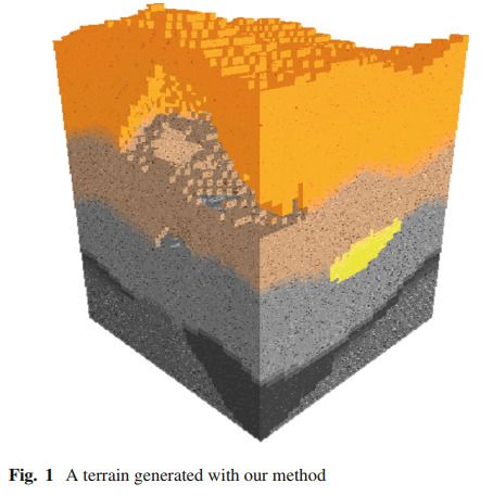
Source notes: Procedural approach to volumetric terrain generation
(Santamaría-Ibirika et al., 2014)
Type: Journal Article
Keywords: Procedural generation, Virtual worlds, Volumetric terrain, Terrain modeling
A new approach to real-time procedural volumetric terrains is proposed by the authors to address the lack of customizability and the problem of evaluating generators that exists in the field. The terrains that can be generated may feature "mineral veins, underground caves, material mixtures and underground material flow".
A significant portion of the paper is given to the explanation of the evaluation of generators, covering such metrics as innovation, structure, speed, usability and so on. As the Masters project is primarily concerned with the structural and visual analysis of the output of generators, the work on evaluation will not be discussed in detail, unless it is specifically related to those areas. The metric defined for structure is as follows:
Structure Ability of the procedural generator to obtain recognizable coupled elements. 0. Random. The results are similar to the random noise 1. The results have independent recognizable elements 2. The results have recognizable coupled elements
This metric is quite broad in how it categorises terrains, however it is useful as providing another way to distinguish between generators, and as such it has informed the visual criteria used in the Masters project. Two other metrics are also applicable to judgement of generated cave models as considered by the Masters project:
Scalability Ability of the procedural generator to obtain results at different scales and levels of detail. 0. The results are always at the same scale. 1. Scalable. The procedural generator can obtain results at different scales and levels of detail. Realism Ability to obtain plausible results. 0. Impossible in any reality. For example, random noise. 1. Plausible in other realities. For example, flying isles. 2. Based on our reality, but not on a simulation (called data free approach by Natalie et al. [12].) 3. Simulation of our reality. (called sparse-data and dense-data approach by Natalie et al. [12].)
The method uses a volumetric data representation with an optimisation that involves dividing a 3D grid of voxels into sections, enabling dynamic generation of voxels when required, therefore improving speed and memory efficiency of the generation process. Generated terrain is made up of layers of materials and uses input data provided during a design stage, consisting of material data and general parameters. Material data define the colour, density, stratification, amongst other attributes of layers and features. Of note is a parameter for deciding the material of empty voxels within the model that can be used to generate different types of caves. A second level of material parameters for each layer, vein and cave is used, controlling such aspects as depth, thickness, roughness, and the amount of blending with other materials. Lastly for material parameters, an affinity value is used to specify how much two separate materials should mix (distinct from blending). General parameters are global to the whole terrain, including those that control overall depth and thickness as well as the area size, density and thickness of all caves and veins.
The terrain generation process starts by creating the deepest layer before adding more layers on top, including veins and caves as determined by the input parameters, continuing until a prespecified number of layers is reached. The affinity between materials in each layer is used to affect the probability that a material is chosen as a constituent of a layer. Thickness and height of each layer is then calculated, with Perlin noise being used to vary height. A fractal algorithm based on midpoint displacement is used to choose the shape of veins, which are generated at random locations within a bounding square in each layer. Lastly, caves are generated in a similar manner to veins, using a random location and bounding square, but they differ in the number of materials used and the area they take up. An additional feature of the method by (Santamaría-Ibirika et al., 2014) is the ability to add to previously generated terrains instead of beginning from scratch.
Performance analysis of the method was performed and documented, comparing to a baseline of a simple Perlin noise terrain. The algorithm developed has a computational complexity of n^2 x m, where n is the side length of a cube-shaped n x n x n terrain and m is the number of layers (proportional to n), resulting in a Big O notation complexity of O(n^3).
Analysis of the terrain with regards to realism was included as part of the research, showing that there are similar characteristics between the generated terrains and real-world sedimentary terrains, such as "stacked layers [...] or propagated folds over the layers". The authors also note that there are layered terrain types that their method is unable to approximate.
The method has various strengths, such as its speed of generation, controllability, scalability (reinforced by online generation) and usability (only requiring the definition of input parameters pre-generation), as well as exhibiting a degree of realism. Detailed images of the cave sections of generated models are not included, making it difficult to judge that aspect in particular. Exploration of the caves by a controllable camera is not discussed and that perspective is not provided in the included images, limiting the degree of comparison to the other methods that have been covered and to the new method being developed. Unless incidental, speleothems do not appear to be a structural feature the method is capable of reproducing. The researchers themselves concede that "the proposed method does not generate complex cave systems, which is a usual feature of volumetric terrains." Overall, the layering approach employed is unique to the sampled literature, increasing variation in the field of terrain generation, and the focus on caves as a desired feature make this research a worthwhile target of comparison for the Masters project.
0 notes
Text
Source notes: Hybrid of Shape Grammar and Morphing for Procedural Modeling of 3D Caves
(Zawadzki, Nikiel, and Warszawski, 2012)
Type: Journal Article
The researchers developed a hybrid system of shape grammars — a system of rules that define behaviour, providing a form of artificial intelligence, that can be used to generate geometric shapes through transforming primitives — and morphing — constructing new shapes based on differing percentage contributions of a base shape and added shapes.
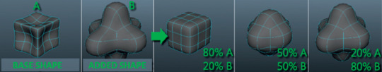
The hybrid system takes the form of a tree structure where the child nodes represent assemblies of shape grammar and morphing functions that are used to transform shapes (via sum, difference, intersection, or morphing operations), and leaf nodes represent the selected shape (geometry is described by functions) such as a sphere, cube, pyramid or torus. Two algorithms produce the output — one to obtain the operations on shapes and a second to render the output.
The shape produced by the tree graph is created within a 3D grid of cube cells and the points within the grid are sampled from a constant distance to create a scalar field. Said field is used to determine if a point is inside, outside, or on the surface of the solid shape based on the sign of the distance. The technique used to generate the mesh for said shape is iso-surface based: when at least two vertices of a cube cell in the 3D grid have the opposite sign in the scalar field, it is checked whether the surface of the solid intersects the cube cell or if it is entirely inside the solid. Linear interpolation is used to find the points where edges of cells intersect the solid. A 256-entry lookup table (as is used in Marching Cubes) is used to find the triangle configuration containing the points of intersection, and then they are displayed. Texturing was achieved separately in a 3D modelling application by importing the generated models.

Evaluation of the results is mainly concerned with generation time vs mesh detail, and verification of the geometry of the generated model using formulae to describe the surface area, volume, concavity and convexity based on the input parameters. Images of the results are provided, however no visual analysis is documented in the paper. From said images the method appears to be capable of producing cave-like structures, containing features approximating tunnels and columns. The level of controllability, customisation and variation in the generation process is not explicitly discussed. Information, or further development work based on the method described, would be required to determine if the techniques used are suitable for creating cave assets for modern games.
0 notes
Text
Source notes: Feature-Based Volumetric Terrain Generation and Decoration
(Becher et al., 2019)
Type: Journal Article
Keywords: Terrain, interactive modeling, volumetric representations, spline curves, diffusion, GPU, surface texture, Ptex
To overcome the limitations of plane based height fields in storing terrain structures with features such as multiple layers, overhangs, and arches, the authors developed a technique using 3D curve-based primitives to achieve volumetric generation of complete terrain surfaces by way of processing input data using diffusion-based algorithms. All stages of the method are GPU-accelerated, using compute shaders. It also enables interactive editing of the generated terrain.
The team behind the paper chose to use parametric 3D spline curves (which they name "feature curves") to model terrain and to constrain the types of scenes produced. Editing terrain features becomes a matter of adjusting curve control vertices and other constraining properties. A GPU-accelerated computational pipeline was developed to generate a volumetric representation of terrain based on said feature curves.
The basis of the method is to use voxelization — the process of converting data structures that store geometric information in a continuous domain into a rasterized image (a discrete grid) — to convert the information defined by the feature curves into vector and scalar fields. Via a diffusion process, a normal vector field is obtained and used to approximate a signed distance field, which matches the constraints defined by the feature curves, from which an iso-surface is extracted using the Surface Nets algorithm (similar to Marching Cubes). User-controlled parameters can then be used to add details via procedural means. Texture mapping is used for rendering, with the output pixels being textured differently depending on which materials were specified on the control points of feature curves (with textures being projected and baked in advance, then fetched during rendering). Additionally, the terrain surface can be combined with imported heightmaps and pre-modelled assets.
It is argued, and demonstrated via results, that feature curves are appropriate for use in a modelling tool for describing terrain due to the fact that they match the shape of features such as ridgelines, river beds and cliffs. The feature curves are constructed using 3D cubic B-splines (curves made by combining cubic polynomials) that are then augmented with "constraint points" (tuples containing data describing the terrain) to control the position and slope of the curve as well as its eventual surface material and noise generation.

The proposed workflow for using the method is to arrange feature curves, heightmaps (intended for use as the ground plane) and other meshes in a scene that can then be used to automatically generate a textured terrain surface mesh. All stages of the terrain generation pipeline operate on a 3D, uniform, regular grid (similar to the Masters project method) to which vector (normal, bitangent, noise and material ID) and scalar (surface information) fields are aligned.
One strength of the method is that it allows, (in theory — only a proof of concept application was produced), precise user-control over the appearance of the generated terrain because of the ability to create and edit feature curves and specify material IDs to define shape and colour. This level of fidelity in controlling the output of a procedural method is uncommon in the reviewed literature.
An effect of the diffusion process used to create the normal vector field the mesh is generated from is the creation of smooth surfaces. This is a limitation of the method in that it decreases the number of different environments and terrain types that can be represented. However, this is balanced by the versatility provided by supporting the addition of other assets to the procedurally generated mesh.

The ability to create overhangs and enclosed areas using the feature curves technique is an advantage of the method over heightmap based approaches, however the paper does not include examples of deep caves, nor does it cover the process of creating larger cave-like spaces. It is not possible to know how suitable the method is specifically for creating cave models.
Performance of the method is largely a factor of the grid size (the Masters project method has the same property).
In terms of cave generation, it is not demonstrated that speleothems are features that can be recreated, however it is logical to think that feature curves could be used to create columns, stalagmites and stalactites. It could be argued that a potential disadvantage of the method is in the amount of manual work required to create complex terrains that are not possible using only heightmap based techniques. The method is perhaps better envisaged as an artist's tool, where precision and art direction are paramount, rather than being applicable to a more purely procedural and automated use case intended to complement manual work.
0 notes
Text
Report Outline
Introduction
Procedural content generation > What it is > Benefits/why it's necessary > Terrain/natural structure generation (incl. caves) Caves in games > Brief history > Some prominent examples > Explain value of developing PCG methods for caves > Mission and scope of research
Literature Review
State scope of review Taxonomy of caves based on real-world and existing game examples Cover research on cave generation methods Analyse methods using criteria based on taxonomy Introduce developed method
Methodology
Rationale behind chosen algorithms and techniques Cellular automata explanation (background and implementation) Marching cubes 33 explanation > Ambiguous cases Dual contouring explanation > QEF Speleothem generation Shaders > Tessellation > Noise vertex displacement > Position-based texturing Collision
Results
List and describe CA rules chosen Figures and descriptions of generated models Visual analysis of models based on previously established criteria Performance analysis and evaluation of method
Discussion
Benefits of method - variation/scale/performance Applicability to modern games and games development Shortcomings/explain issues and negative points of analysis from results section
Conclusion and Future Work
Summarise Larger cave systems More control over generation Generate caves in existing environments/meshes Audio work More types of speleothems More versatility in vegetation generation Water simulation
0 notes
Text
Source notes: Explicit Generation of 3D Models of Solution Caves for Virtual Environments
(Boggus & Crawfis, 2009)
Type: Journal Article
Keywords: Synthetic Environments, Caves, Phreatic Passage, Vadose Passage, and Combination Passage
Relevance: 3/5
The authors endeavour to create virtual caves by understanding and observing how they are formed in reality. Their method produces different 3D models based on two types of cave passages, that can then be combined to form larger systems.
The paper begins by briefly mentioning some computer games (the abstract mentions movies in relation to virtual environments but the researchers' focus seems to be on games), Dig Dug, Tomb Raider and Halo. They proceed to discuss the need for, and merits of, procedural generation of content due to the increasing complexity of 3D environments in games and the power of algorithmic methods, as well as the relative paucity of research on the generation of caves.
A definition of caves is given as "natural voids underground that are large enough for a person to enter". The type of cave being recreated is a solution cave, formed when rock is dissolved by acidic water. A process which can take several thousands of years, and which requires there to be "sufficient groundwater recharge to dissolve rock and enough drainage of the solution to remove sediment from the area". It is solution caves that speleothems (mineral formations) are often found in, a result of precipitation after the formation of the main cave passages. As speleothems are visually interesting, recognisable as cave features and found in most examples of computer game caves, the Masters project and its technical artefact will also focus on solution caves.
Referenced are examples of polygonal models created using spatial data of caves from surveys. Such examples are insufficiently detailed and inflexible for computer games but may be worth referencing to illustrate the challenges of 3D cave generation. The same can be said in terms of the cost and time investment — and again, static nature of — cave models based on spatial data obtained by laser and ultrasound scanning, which (Boggus & Crawfis, 2009) also mention.
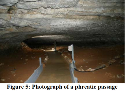
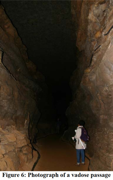
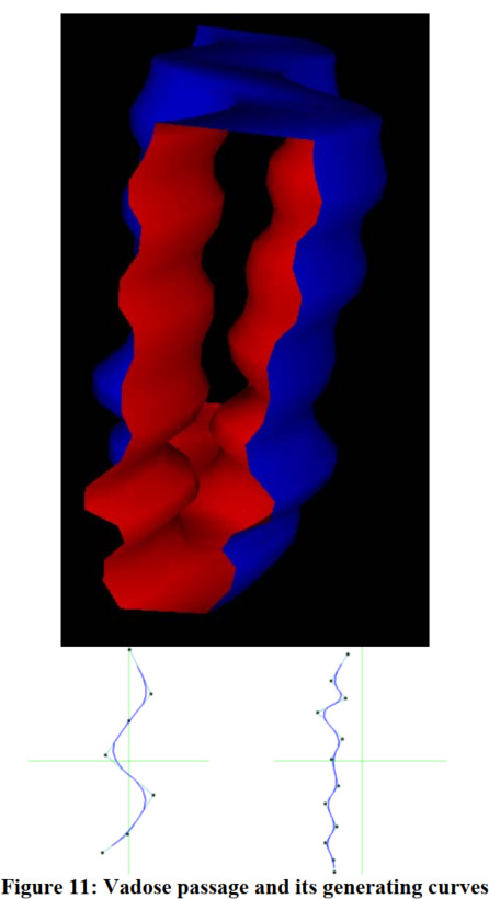
Two types of cave passages are described, phreatic and vadose. Phreatic passages are rounded and horizontal in shape, widened in all directions. Vadose are vertical slots formed by rapidly moving and descending water.
The technique used to model these passages involves extruding one Bezier curve (a smooth, continuous curve created using "control points" as parameters to a formula) along the trajectory of another.
For phreatic passages, the following curves are used:
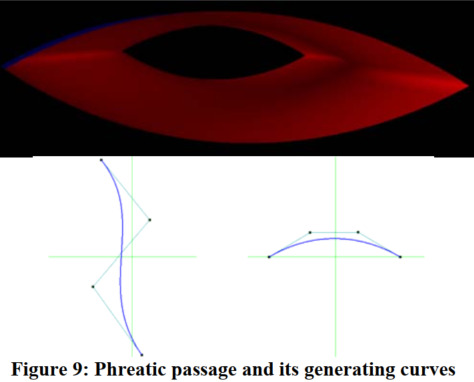
The curve on the right is extruded along the curve on the left (representing the flow of water). The resulting surface is copied and reflected to create both the ceiling and floor of the passage. A quadratic equation is used to create curves of differing heights and widths that can then be extrudede.
Vadose passages are created in a similar manner. The curve on the right is "swept" along the curve on the left to create one wall, before repeating with the trajectory curve reflected. The tops and bottoms of each wall are then connected.
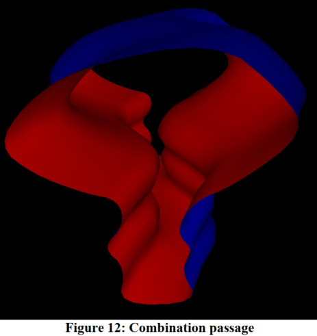
Combination passages are created by sweeping cross sections along trajectory curves or by combining models of separate passages and eliminating clipping vertices and vertices from one passage that are inside the cavity of another.
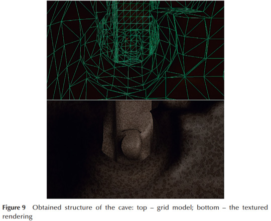
The paper concludes by presenting textured models and suggesting that cave features and surface details could be created through techniques such as bump mapping and displacement mapping.
The method used is simple and computationally inexpensive. It makes it easy to create varied surfaces and passage shapes. However, a lot of work is required to join passages and create larger systems. There is no detailed information on generating speleothems. Features such as collision detection and texturing are not covered, nor is parameterisation or customisation of the models outside of altering the input curves. It is relevant to include as an example of a basic method for generating virtual caves and because it uses a unique technique.
0 notes