
Don't wanna be here? Send us removal request.
Statistics
We looked inside some of the posts by raysteppermotor and here's what we found interesting.
Average Info
Notes Per Post
1
Likes Per Post
1
Reblog Per Post
0
Reply Per Post
0
Time Between Posts
21 days
Number of Posts By Type
Text
6
Last Seen Tumblr Blogs


Fun Fact
Mobile Tumblr US users spend an average of 4.04 minutes per session on the app.
Text
Worm reduction gearbox structural advantages and selection criteria
1.Definition and basic principle of worm reduction gearbox A worm reduction gearbox is a mechanical device that uses the meshing transmission of a worm and a worm wheel to achieve speed reduction. The worm is similar to a screw and has a large lead angle, while the worm wheel is a gear with a special shape. When the worm rotates, the power is transmitted to the worm wheel through the interaction between the helical tooth surface of the worm and the tooth surface of the worm wheel, thereby achieving speed reduction.

2.Main components of worm reduction gearbox
1.Worm and worm wheel: The core transmission components of worm reduction gearbox are worm and worm wheel. The worm is similar to a screw and has a large lead angle, while the worm wheel is a gear with a special shape. They achieve speed reduction through meshing transmission. When the worm rotates, the power is transmitted to the worm wheel through the interaction between the helical tooth surface of the worm and the tooth surface of the worm wheel, thereby achieving speed reduction.
2.Bearings and shafts: The main functions of bearings and shafts are to support and fix gears, reduce friction and wear, and ensure smooth operation of shafts. The parts on the shaft are fixed axially by the shaft shoulder, sleeve and bearing cover. Deep groove ball bearings are usually used to bear radial loads and small axial loads. When the axial load is large, angular contact ball bearings, tapered roller bearings or a combination of deep groove ball bearings and thrust bearings will be used. 3. Housing: The housing is the main component of the reducer, providing support and protection, accommodating internal components, and ensuring good lubrication and sealing. The housing is usually made of gray cast iron, and cast steel housing can also be used for reducers with heavy loads or impact loads. The housing is made horizontally split along the axis, and the upper housing cover and the lower housing are bolted together. 4. Lubrication and sealing system: The lubrication system ensures that the gears and bearings are fully lubricated to prevent the loss of lubricating oil and the entry of external impurities. The sealing element is used to prevent the leakage of lubricating oil and the entry of external dust into the housing to ensure the normal operation of the reducer.
3.Structural advantages of worm reduction gearbox
1.Compact structure: The worm reduction gearbox can achieve a larger transmission ratio in a smaller space through the line contact meshing of the worm and the worm wheel. This makes the worm reduction gearbox more compact in structure and suitable for space-constrained occasions, such as elevator traction systems, AGV logistics vehicles and medical equipment. 2. Large transmission ratio: The worm reduction gearbox can achieve a larger transmission ratio, usually 5:1 to 100:1, or even higher. This enables the worm reduction gearbox to achieve a larger speed reduction in a smaller space and meet the needs of different equipment. 3. Smooth transmission: The transmission process of the worm reduction gearbox is relatively smooth, with low noise and low vibration. The meshing of the worm wheel and the worm is continuous, without the impact and vibration in the gear transmission, and is suitable for use in occasions requiring low noise and high stability, such as precision instruments and equipment and textile machinery. 4. Reverse self-locking: When the lead angle of the worm is less than the friction angle, the worm reduction gearbox has the self-locking function of irreversible transmission. This feature is very useful in situations where reversal needs to be prevented, such as crane hooks and automated warehouse lifting mechanisms, which can achieve mechanical self-locking in the power-off state to prevent the load from slipping. 5. Low noise: The noise of the worm reduction gearbox is lower than that of the gear reducer. The meshing of the worm wheel and the worm is multi-point contact, and the load is evenly distributed on multiple contact points, reducing stress concentration and thus reducing noise. 6. Strong load-bearing capacity: The worm wheel and worm of the worm reduction gearbox are usually made of high-strength materials, and are precision machined and heat-treated, with strong load-bearing capacity. It can withstand large loads and is suitable for situations where large torque needs to be transmitted.

4.Selection criteria for worm reduction gearbox
1.Transmission ratio and speed ratio calculation: The ideal reduction ratio needs to be calculated when selecting. The calculation formula for the reduction ratio is: reduction ratio = motor speed (standard speed 1400 rpm) / speed of the output shaft of the reducer. Selecting a model close to the ideal reduction ratio can improve the efficiency and life of the reducer. 2. Torque calculation: Torque calculation is crucial to the life of the reducer. It is necessary to ensure that the maximum load torque of the reducer is not less than the required maximum torque value to avoid overload damage. 3. Load type and duty: Select a suitable reducer according to the load type (constant torque, variable load or impact load) and duty (continuous operation or intermittent operation). For example, for applications that require frequent starting and stopping, it is more appropriate to select a reducer with a higher safety factor. 4. Environmental conditions: Consider the use environment (such as outdoor, high temperature, dust, etc.) to select a reducer with a corresponding protection level (such as IP65) or special coating to ensure its reliable operation in harsh environments. 5. Lubrication method: Select the lubrication method according to the working conditions. By default, grease lubrication is used, but forced oil lubrication can be selected under high speed or high temperature conditions. 6. Installation method: Select different installation methods such as foot installation, flange installation or shaft installation according to the installation space. 7. Maintenance and troubleshooting: Understand the maintenance cycle of the reducer and common troubleshooting methods, such as regularly checking the oil level and sealing, and regularly changing the lubricating oil, etc.
Source:https://community.networkofcare.org/blogs/randy/archive/2025/05/10/worm-reduction-gearbox-structural-advantages-and-selection-criteria.aspx
0 notes
Text
How to control the CNC spindle motor?
1.Definition of CNC spindle motor A CNC spindle motor is a critical component in a CNC machine, the main function of the spindle motor is to drive the spindle of the mechanical equipment to rotate, so as to complete tasks such as processing and cutting. Its performance directly affects the processing accuracy, efficiency and stability of the equipment.

2.Working principle of CNC spindle motor The operation of the CNC spindle motor is based on the principle of electromagnetic induction. When AC is applied to the three-phase winding, a rotating magnetic field is generated in the stator. This rotating magnetic field cuts the rotor conductor, thereby generating an induced current in the rotor conductor. The induced current interacts with the rotating magnetic field to generate an electromagnetic force that drives the rotor to rotate. There is a certain difference between the speed of the rotor and the speed of the rotating magnetic field. This difference is called the slip. By controlling the slip, the spindle motor speed can be precisely controlled.
3.Components of CNC spindle motor
Stator:The stator is the stationary part of the motor and houses the windings. It is responsible for generating the magnetic field that interacts with the rotor.
Rotor:The rotor is the rotating part of the spindle motor. It is driven by the magnetic field created by the stator. The rotor is connected to the spindle shaft, which directly drives the cutting tool.
Bearings:Bearings support the spindle and allow it to rotate with minimal friction. High-quality bearings are crucial to ensure that the spindle motor operates smoothly and accurately, as they help to reduce vibrations and ensure precision during operation.
Spindle Shaft:The spindle shaft is the central part that connects the rotor to the tool being used in the machining process.
Cooling System:Cooling systems are vital to keep the spindle motor temperature within safe operating limits, especially during high-speed operation.
Encoder:The encoder provides feedback on the position and speed of the spindle motor. It allows the CNC system to accurately control the motor's speed and positioning by sending signals about the rotor's movement to the machine's control system.
Drive System:The drive system consists of components that convert electrical energy into mechanical energy to rotate the spindle. It includes components like the motor controller, inverter, and drive circuitry.
VFD (Variable Frequency Drive):The VFD is used to control the motor's speed by adjusting the frequency of the electrical supply.
Cooling Fan:A cooling fan (or ventilation system) is sometimes incorporated into the motor assembly to provide active air cooling.
Housing:The housing is the outer casing of the spindle motor that protects the internal components, such as the stator, rotor, and bearings, from dirt, debris, and damage.
Electrical Connections:These are the wiring and connectors that supply power to the motor and interface with the CNC controller and other components.
Feedback System:Some advanced spindle motors include additional feedback systems, such as tachometers or resolvers, which provide more precise information on motor speed and position.

4.The control modes of CNC spindle motor
Constant Speed Control Mode:In this mode, the spindle motor runs at a fixed, constant speed throughout the machining process.It is used for operations where the tool does not need to change its speed dynamically during the process.
Constant Torque Control Mode:This mode adjusts the motor’s speed to maintain a constant torque throughout the operation, ensuring the motor delivers consistent cutting force.This is ideal for machining operations where the cutting load varies but the motor's torque needs to remain steady to prevent tool stalling.
Vector Control (Field-Oriented Control, FOC) Mode:Vector control provides high precision and dynamic control of the motor by controlling the magnetic field inside the motor. It adjusts both the torque and speed based on real-time demands.This mode is particularly useful in high-performance CNC systems, providing smoother operation, better acceleration/deceleration, and high-speed control.
Closed-Loop Control Mode:Closed-loop control involves a feedback system where the motor speed, torque, and position are continuously monitored, and adjustments are made in real-time to keep the system running optimally.Feedback devices like encoders or resolvers help achieve high precision and accuracy by adjusting motor parameters to ensure the desired output is achieved.
Open-Loop Control Mode:In open-loop control, there is no feedback mechanism to adjust the motor’s operation based on real-time performance.The motor is controlled based on pre-set parameters, such as speed or power, without ongoing monitoring or adjustments.
Synchronous Motor Control:Synchronous motors operate at a fixed speed, determined by the frequency of the electrical supply.These motors are typically used when precise speed control is required, as they run at a constant speed without fluctuating under load.
Dynamic Brake Control Mode:Dynamic braking is often used for rapid deceleration of the spindle motor after the machining process is completed.This method uses the motor itself to dissipate the kinetic energy, slowing down the motor quickly by converting it into heat.
Speed and Torque Control Mode (Dual Mode):This control mode combines both speed and torque control to give the spindle motor the ability to adjust both parameters simultaneously.
0 notes
Text
The main functions and common applications of servo motors
1.A brief introduction to servo motors A servo motor is an engine that controls the operation of mechanical elements in a servo system. It is an auxiliary motor indirect speed change device. A servo motor can convert voltage signals into torque and speed to drive the control object. Its core features are very high control speed and position accuracy. It can be used as an actuator in an automatic control system and has characteristics such as small electromechanical time constant and high linearity.

2. Structural components of servo motors 1. Stator: Made of laminated silicon steel sheets, with three-phase windings embedded to form a rotating magnetic field. The stator is the fixed part of the motor, usually called the excitation winding of the motor. 2. Rotor: Made of permanent magnetic material, it rotates with the rotating magnetic field. The rotor is the rotating part of the motor, usually called the armature winding. 3. Encoder: Used to detect the position and speed of the rotor, usually installed on the rotor shaft. The encoder has an approximate sensor that can determine the speed and revolutions per minute of the motor. 4. Driver: Receives instructions from the controller and converts them into drive signals to control the operation of the servo motor. The driver controls the speed and direction of the rotating magnetic field by controlling the current of the three-phase coil, thereby controlling the speed and direction of the servo motor.
3.The main functions of the servo motor 1. Accurately control the speed and position: The servo motor can accurately control the speed and position according to the change of the voltage signal to achieve uniform and stable movement. It is positioned by pulse signals. Every time a pulse current is received, it will rotate a corresponding angle, thereby achieving high-precision positioning with an accuracy of up to 0.001mm. 2. Convert voltage signals into torque and speed: The servo motor can convert the input voltage signal into torque and speed to drive the control object. This feature makes it an important actuator in the automation control system. 3. Fast response and high-precision feedback: The servo motor has the characteristics of fast response and can respond to the input signal in a short time. At the same time, it uses a closed-loop control system to feedback pulse signals in real time to ensure the accuracy of motion control. 4. Suitable for high-precision positioning scenarios: Servo motors are widely used in scenarios that require precise positioning, such as CNC machine tools, steering gears, etc. Its fast start-stop speed, small rotational inertia, large starting torque and rapid braking make it perform well in these fields. 5. Core role in servo system: The servo motor is a key component in the servo system, used to control the operation of mechanical elements. It achieves high-precision motion control by converting electrical signals into angular displacement or angular velocity output.

4.Common application industries of servo motors 1. Industrial automation: Servo motors are commonly used in CNC machine tools, printing equipment, packaging machinery and food processing equipment, etc., which can achieve high-precision and high-speed motion control and significantly improve production efficiency and product quality. In automated production lines, servo motors are used in robotic arms, conveyor belts, assembly machines, etc. to achieve precise position and speed control. 2. Robotics: Servo motors are key components of robot joint drives, which can convert electrical energy into mechanical energy, enabling robots to perform precise movements according to predetermined paths and motion modes. 3. Aerospace: Servo motors are used for attitude control and rudder drive of aircraft to ensure stable flight of aircraft in various environments. 4. Automotive manufacturing: Servo motors are used in engine management, brake systems, steering systems, etc. in automotive manufacturing to improve the performance and safety of automobiles. 5. Medical equipment: Servo motors are widely used in surgical robots, X-ray machines, CT scanners and other equipment to improve the accuracy and safety of medical operations. 6. Research equipment: Servo motors are used in scientific research for precision measurement, data analysis and other equipment to improve the accuracy and reliability of experiments. 7. Other industries: Servo motors are also used in medical examination equipment such as CT machines, B-ultrasound machines, and MRI machines to move patients; in the food packaging industry, such as the vacuum packaging production of snacks such as French fries; in the logistics and transportation industry, such as AGV vehicles in large storage warehouses for the transportation and allocation of goods; in microelectronics production and processing, such as chip production; and in cutting machines, such as water jet machines, which require servo motors to move the cutter head.
0 notes
Text
Main classification and function of stepper motor encoders
1.What is a stepper motor encoder? A stepper motor encoder is a device used to feedback the motion state and position of a stepper motor. It senses the motor's rotor motion, determines the motor's position and direction, and feeds this information back to the controller so that the controller can control the motor's motion. Stepper motor encoders can accurately measure motor motion and improve the accuracy and reliability of the control system.
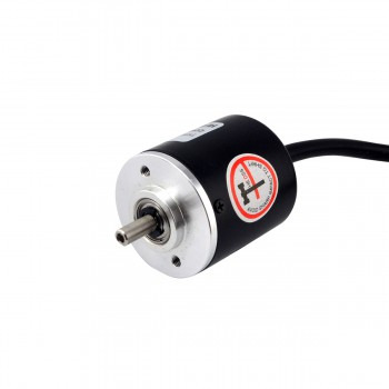
2.Main classification of stepper motor encoders 1.Incremental encoders: Incremental encoders output three sets of square wave pulses A, B and Z phases through the principle of photoelectric conversion. The phase difference between the A and B groups of pulses is 90 degrees, which is used to determine the direction of rotation, while the Z phase is one pulse per revolution, which is used for reference point positioning. Its advantages are simple principle and structure, long average mechanical life, strong anti-interference ability, and suitable for long-distance transmission. The disadvantage is that it cannot output the absolute position information of the shaft rotation. 2.Absolute encoders: Absolute encoders directly output digital signals. There are several concentric code disks on the circular code disk, and there are light-transmitting and light-impermeable sectors on each track. When the code disk is in different positions, the photosensitive element converts the corresponding level signal according to whether it is illuminated or not, forming a binary number. Its characteristic is that there is no need for a counter, and a fixed digital code can be read at any position of the rotating shaft, which is suitable for applications that require high-precision positioning. 3.Hybrid absolute encoder: This encoder outputs two sets of information, one for detecting the magnetic pole position, with absolute information function; the other is completely the same as the output information of the incremental encoder. This encoder combines the advantages of incremental and absolute types and is suitable for occasions that require high-precision and absolute position information.
3.Main functions of stepper motor encoders 1.Measuring position: The stepper motor encoder can accurately measure the position of the motor. By processing the photoelectric signal, the encoder can calculate the rotation angle of the motor and thus determine the current position of the motor. This function is very important for applications that require high-precision positioning. 2.Measuring speed: The encoder can measure the speed of the motor by calculating the position change of the motor at each moment. This is particularly important for applications such as high-precision positioning, motion control and adaptive control, and can help the system adjust the control parameters in real time to improve motion accuracy and positioning accuracy. 3.Improve motion control accuracy: By providing deterministic feedback signals, the encoder can ensure accurate position control and eliminate errors caused by load changes or environmental factors. In addition, the encoder can provide more accurate speed feedback information, improve the motor's motion performance, and reduce noise and vibration. 4.Improve system stability and achieve closed-loop control: The encoder can monitor the motor's operating status in real time, such as speed, torque and other parameters. When the motor is abnormal, the controller can take timely measures, such as reducing the speed or stopping the operation, to protect the motor. In addition, the encoder is used in combination with the controller to achieve closed-loop control and improve the system's response speed, stability and accuracy. 5.Prevent overshoot and undershoot: Through the actual speed information provided by the encoder, the controller can effectively adjust the motor's operation to avoid overshoot or undershoot, thereby improving the system's operating performance.

4.Maintenance methods for stepper motor encoders 1.Regularly check the mechanical part: Check the mechanical part of the encoder every month to ensure that the mechanical connection points are not misaligned or loose, and maintain their stability. 2.Keep the cable connection in good condition: Check the status of the encoder connection cable regularly to ensure that the cable is not broken, short-circuited or in poor contact. If these problems are found, replace the cable or connector in time, and ensure that the cable is firmly fixed to avoid open welding or broken circuit caused by looseness. 3.Power supply voltage management: Ensure that the power supply voltage of the encoder is within the specified range, usually not less than 75V. If the power supply voltage is too low, it is necessary to repair the power supply or replace the cable. 4.Battery replacement and maintenance: For absolute encoders, check the battery voltage regularly, replace low-power batteries in time, and ensure that the reference point position memory is not lost. 5.Shielded wire grounding: Ensure that the shielded wire of the encoder cable is reliably welded and properly grounded to reduce the introduction of interference signals, ensure waveform stability and communication accuracy. 6.Prevent loose installation: Check the installation status of the encoder regularly to ensure that it is stable and reliable, and avoid reduced position control accuracy or servo system overload alarm due to loose installation. 7.Clean the grating: Clean the grating regularly to avoid grating contamination affecting the signal output amplitude. You can use cotton wool dipped in anhydrous alcohol to gently wipe off the oil on the grating. 8.Professional maintenance: Since the encoder is a precision instrument, its maintenance and care should be performed by professionals. Non-professionals should not operate or adjust the encoder and its related equipment without authorization.
Source:https://community.networkofcare.org/blogs/randy/archive/2025/03/03/main-classification-and-function-of-stepper-motor-encoders.aspx
0 notes
Text
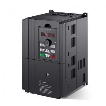
Functions and application scenarios of variable frequency drives
1.What is a variable frequency drive? A variable frequency drive is a power electronic device that is mainly used to control the operation of motors, especially induction motors. It achieves precise control of the motor speed by changing the power frequency and voltage supplied to the motor. The core functions of VFD include energy saving, improving equipment performance, extending equipment life, and reducing maintenance costs.

2.Working principle of variable frequency drive The working principle of VFD is based on the change of power supply voltage and frequency. It mainly consists of three parts: rectification part, filtering part and switch or inverter part. The rectification part converts the three-phase AC signal into a single DC power rail, the filtering part removes the AC ripple through large capacitors and inductors to provide a smooth DC output, and finally the switch or inverter part inverts the DC power into AC power to control the speed of the motor.
3.Functions of variable frequency drives 1.Speed regulation function: The variable frequency drive achieves stepless speed regulation of the motor by changing the frequency of the AC power. This means that the speed of the motor can be adjusted at any time according to production needs, whether it is fast start or slow operation, it can be easily achieved. 2.Energy-saving function: The variable frequency drive can adjust the speed of the motor according to the load demand, prevent the motor from running at the rated speed for a long time and causing waste, thereby reducing energy consumption. By controlling the running speed of the motor, energy can be saved while meeting production requirements. 3.Automatic control: The variable frequency drive is used together with the sensor to realize closed-loop control, automatically adjust the running state of the motor according to the feedback signal and the set control program, and realize automatic control. 4.Motor protection: The variable frequency drive has protection functions such as overcurrent, overload, and overvoltage. It can automatically cut off the power supply when the motor is abnormal, avoid motor damage, and protect the safety of equipment and systems. 5.Noise reduction and vibration reduction: The variable frequency drive can reduce the noise and vibration of the motor during operation and improve the stability and reliability of the equipment. 6.Increase the life of the motor: By controlling the start and stop, speed and load parameters of the motor, the variable frequency drive can extend the service life of the motor and reduce unnecessary wear and damage. 7.Self-diagnosis function: The variable frequency drive can automatically detect the running state and faults of the motor and improve the reliability and stability of the equipment.
4.Main application scenarios of variable frequency drives 1.Fan and pump loads: Variable frequency drives control air volume or flow by adjusting the motor speed to achieve energy saving. For example, many water companies' water pumps, chemical pumps in the chemical and fertilizer industries, etc. use variable frequency speed regulation, which has significant effects. 2.Household appliances: Variable frequency air conditioners, refrigerators and other equipment use variable frequency drives to adjust the cooling capacity and improve energy saving effects. For example, variable frequency air conditioners can effectively reduce energy consumption during peak power consumption in summer. 3.Production equipment: Rolling mills, elevators and other equipment require precise control of motor speed to achieve automation and efficient production. For example, rolling mills in the metallurgical industry use AC-DC-AC inverters to meet the needs of low-frequency load starting, synchronous operation between racks, constant tension control, etc.. 4.Precision equipment: CNC machine tools, robots and other equipment require high-precision control of motor speed and torque to achieve precise motion control and processing. For example, roller loads in the steel and metallurgical industry use AC motor variable frequency control to improve equipment reliability and stability. 5.Heavy industry: Water treatment, chemical industry, metal processing and other fields use variable frequency drives to save energy, reduce noise and improve equipment operation stability. For example, chemical pumps in the chemical industry and mud pumps in the non-ferrous metal industry use variable frequency speed regulation with good results. 6.Other industry applications: Variable frequency drives are also widely used in large industrial rotary kilns (converters) such as metallurgy, building materials, caustic soda, as well as crushers, ball mills and other loads. For example, crushers and ball mills used in metallurgy, mining and building materials have significant effects after using variable frequency.
Source:https://community.networkofcare.org/blogs/randy/archive/2025/02/06/functions-and-application-scenarios-of-variable-frequency-drives.aspx
0 notes
Text
Main features and selection principles of geared stepper motors
1.Brief introduction to geared stepper motors Geared stepper motors are a device that combines stepper motors and gear mechanisms, and are mainly used to increase the output torque and reduce the speed of stepper motors. The stepper motor itself is a motor that converts electrical pulse signals into angular displacement or linear displacement. Each time an electrical pulse signal is received, the motor rotor will rotate a fixed angle or move forward.

2.Working principle of geared stepper motors The working principle of geared stepper motors is based on the basic working principle of stepper motors. The stepper motor receives an electrical pulse signal, and each pulse causes the rotor to rotate a fixed angle. When the stepper motor is combined with a gear mechanism, the gear mechanism can amplify the torque output of the motor, so that the motor can provide greater power at low speeds, while reducing the speed and increasing the output torque.
3.Main features of geared stepper motors 1.Accurate positioning capability: Geared stepper motors can provide higher output torque and more precise position control through a gear transmission system. The gear ratio can amplify the output torque of the motor, so that the motor can still provide a large torque at low speeds, which is suitable for application scenarios that require high-precision positioning. 2.High torque output: Due to the transmission effect of gears, geared stepper motors can provide higher torque output at low speeds, which is very beneficial for applications that require high torque. In addition, gear transmission can also reduce the vibration and noise of the motor and improve the stability of the system. 3.Easy to control: Stepper motors are controlled by electrical pulse signals, which are easy to implement open-loop control and do not require a complex feedback system. This makes stepper motors widely used in systems that require simple control, such as CNC machine tools. 4.No cumulative error: The output angle of the stepper motor is strictly proportional to the number of input pulses, and there is no cumulative error. This makes the stepper motor perform well in systems that require high-precision position control. 5.Applicable scenarios: Due to these characteristics of stepper motors, they are widely used in CNC machine tools, automation equipment, robots, printers, and other fields that require precise control and positioning.

4.Selection principles of geared stepper motors 1.Load capacity: The selection of geared stepper motors must first consider their load capacity, including factors such as load size, inertia, and acceleration. If the load is too large, a stepper motor with greater torque output needs to be selected, usually by increasing the number of stator electromagnetic windings. 2.Accuracy requirements: Accuracy is one of the important considerations for selecting a geared stepper motor. The step angle and nominal resolution of the stepper motor directly affect the accuracy of the rotation. Smaller step angles correspond to higher accuracy requirements. 3.Power supply and controller: The quality of the power supply and controller has a significant impact on the reliability and stability of the stepper motor. An unstable power supply or a controller that cannot be accurately controlled may cause the rotation to stall or lose reliability. 4.Step angle: The step angle is the angle that the stepper motor rotates each time it receives an electrical pulse signal. The choice of step angle depends on the load accuracy requirements. For high-precision positioning, a motor with a smaller step angle should be selected. 5.Static torque: Static torque refers to the maximum torque that a stepper motor can generate when it is stationary. When selecting static torque, the type of load the motor is working on needs to be considered, including inertial load and friction load. Generally, the static torque should be 2-3 times the friction load to ensure that the motor has sufficient torque reserve during startup and operation. 6.Current: Motors with the same static torque will have very different operating characteristics due to different current parameters. To select a suitable current value, you need to refer to the torque-frequency characteristic curve of the motor, and try to choose a smaller current value to reduce heat generation and energy consumption while meeting the torque requirements. 7.Relationship between speed and torque: The output torque of the stepper motor will gradually decrease with the increase of speed. When selecting, you should refer to the torque-frequency characteristic curve of the motor based on the maximum speed and required torque of the load, and select a motor that can provide sufficient torque within the working speed range. 8.Subdivision drive: Try to choose a subdivision drive and make the drive work in a subdivision state to improve the control accuracy and running stability of the motor.
Source:https://community.networkofcare.org/blogs/randy/archive/2025/01/03/main-features-and-selection-principles-of-geared-stepper-motors.aspx
1 note
·
View note