
Don't wanna be here? Send us removal request.
Statistics
We looked inside some of the posts by ricardophysicalcomputing and here's what we found interesting.
Average Info
Notes Per Post
0
Likes Per Post
0
Reblog Per Post
0
Reply Per Post
0
Time Between Posts
11 days
Number of Posts By Type
Text
8
Last Seen Tumblr Blogs


Fun Fact
Total funding amounts to $125.3M.
Text
All the project files/photos/videos
https://drive.google.com/open?id=1amT28uQtwHBMGexNDt4d-_WpGCGkyXJK
0 notes
Text
Week 6
This week I’ve decided to try and create a heater for my final project. After looking around on how to generate heat using electronics I came to the conclusion that the cheapest (and most fun) way of producing heat would be using resistors.
A resistor is a passive two-terminal electrical component that implements electrical resistance as a circuit element. In electronic circuits, resistors are used to reduce current flow, adjust signal levels, to divide voltages, bias active elements, and terminate transmission lines, among other uses. These resistors can also create heat. As a massive oversimplification, this happens due to a property of all materials, called electrical resistance. When attached to a power supply, resistors will dissipate some of the energy they receive as heat.
First of all, decide how many Watts of power (P) you need to dissipate, after that check on the wattage (W) of your resistors and then lastly the voltage (V) of your power supply. In my case these translate to P -> 5, W -> 0.25 and V -> 12.
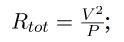
We then apply this equation where we replace V and P with our values. Using my values that will be (12*12)/5 = 28.8 (Rtot). This is how much resistance we need to dissipate the desired power. After that we apply this equation.
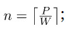
This equation will give us the number of resistors we need. Applying my numbers again this will be equal to 5/0.25 = 20 (n). So I’m gonna need 20 resistors. Now finally let’s find out how much resistance each resistor needs. We’ll be using this final equation.
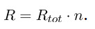
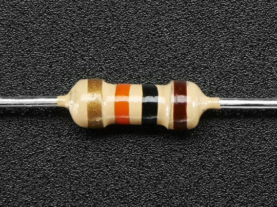
Which gives us 28.8*20=576 Ohm. Now that we concluded these equations we know that we will need 20 576Ohm resistors to dissipate 5W of heat on 12V. How do we find out which resistors are the right ones though? We will use the resistor colour chart seen below.
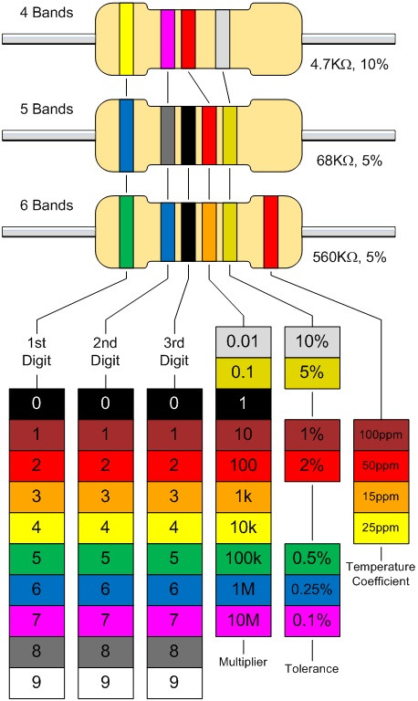
Following this chart we now know that our resistor must be green, purple and blue. Unfortunately I didn’t have any of those resistors laying around so instead I used 680Ohm ones which are blue, grey and black.
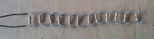
Now how do we connect them? Heating strips are usually made by connecting all the resistance in parallel, arranged in what is called a resistor ladder. This is what it looks like.
Since I don’t have a way of soldering the resistors I instead put the resistors on a breadboard in parallel. Here’s how it looks like.
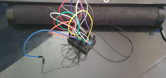
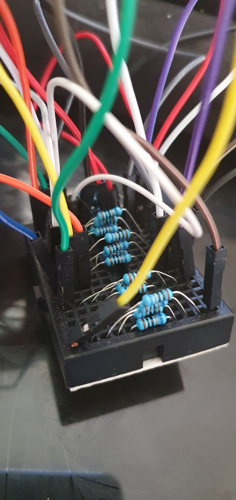
Conclusion: It works and it produces heat! Just be careful not to touch them because they can get extremely hot!
0 notes
Text
Week 5
This week I decided to play around with water pumps so that I know how they work and if I can use them in my final project. A pump is a device that moves fluids by mechanical action, typically converted from electrical energy into hydraulic energy. For this week I’m going to try to irrigate a small pot using a water pump and a soil moisture sensor.
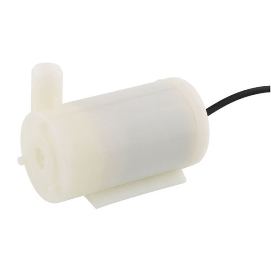
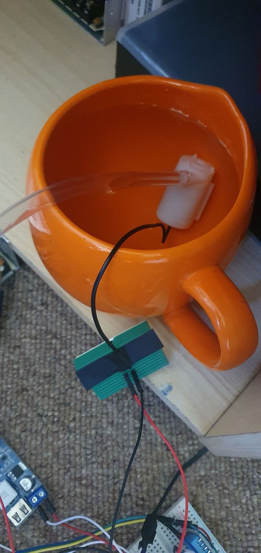
The water pump takes 5V and needs to be submerged in water. It has 2 wires, a VCC and a GND. It has a small motor that rotates fast enough to move the water from one end to the other. Here’s how it looks like when it’s working.
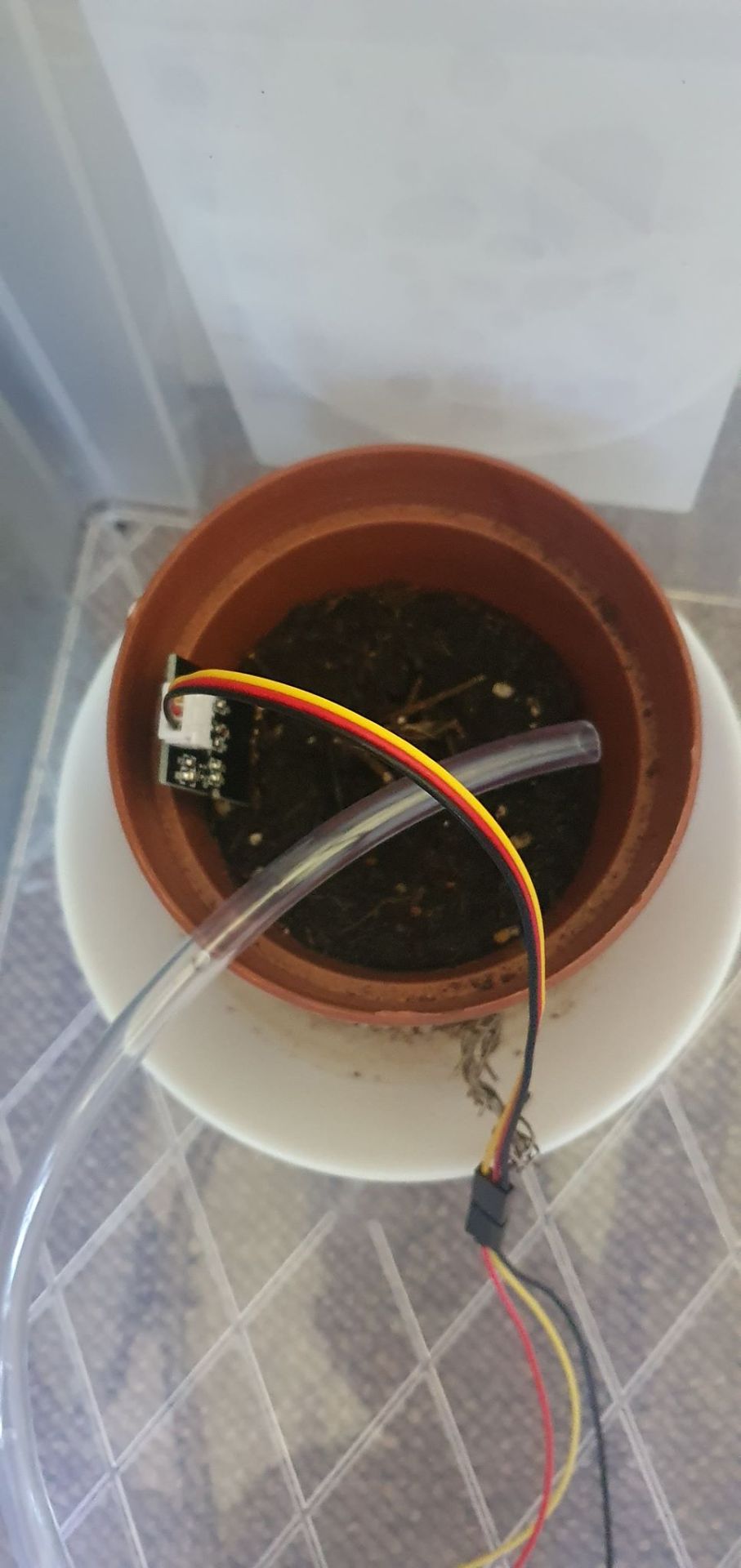
This pump combined with a soil moisture sensor creates an automated system where the Arduino can read the soil moisture and then decide when to irrigate the field again using the water pump. It’s called an automated irrigation system. Here’s how the soil moisture sensor looks like.
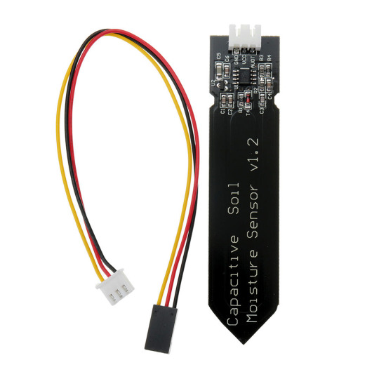
All you have to do is bury it until around the “v1.2″ and it will start doing analog readings of the soil moisture which we can then transform into 0-100%.
So how do we connect everything together? Here’s how.
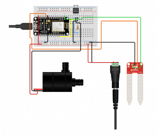
Since the water pump requires quite a lot of power an external 5V supply is given to the circuit powering both the NodeMCU and the water pump. We then use a MOSFET to control the pump activation. A MOSFET works similar to a transistor (an electric switch) or even a relay (another kind of electric switch), the difference is that a MOSFET can regulate the amount of power going through it so it works kinda like an electric potentiometer where we can choose how strong we want the current to be via the coding pins (PWS).
So the way this system is working is by reading the soil moisture values and then irrigating the soil once it gets to lower than 70% soil humidity. Here’s the code.
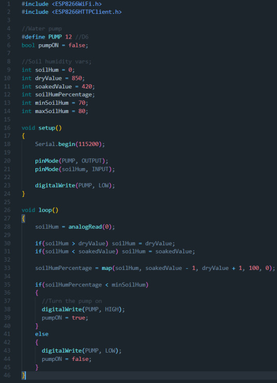
And here’s some photos and videos of how it looks/works.
vimeo
0 notes
Text
Week 4
This week I’ve learnt about stepper motors and how they work. A stepper motor is a brushless dc electric motor that divides a full rotation into a number of equal steps. This allows it to be controlled precisely without the use of a position sensor. Below it’s a cool demonstration of how it works. Source
There are 4 magnets that when activated rotate the gear inside the motor. I’ve decided to try to control one using an Arduino. The stepper motor I was using was a 12V one which meant that I couldn’t simply plug it into the Arduino, I would need an external power source. I got a small transformer to charge other electronics and cut the end socket so that I could expose the live wires.
Then another problem came through which is the fact that the Arduino itself cannot control the stepper motor without using a stepper motor driver. The one I used was a A4899, it’s a tiny red board with 16 pins.
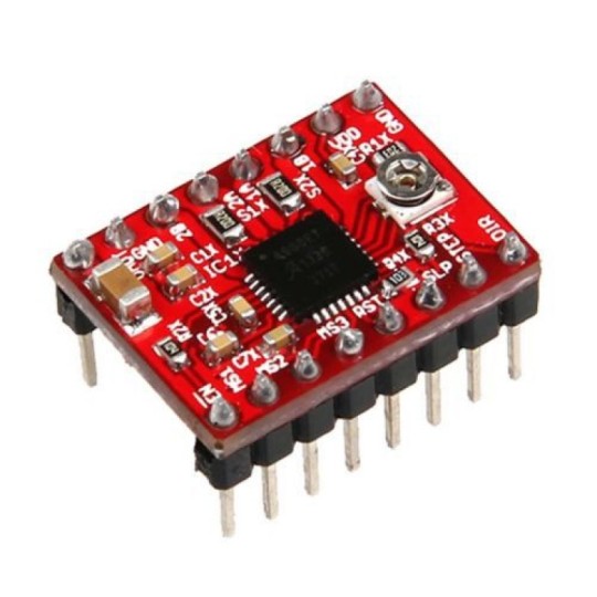
This stepper motor driver is able to take the 12V to power the stepper motor while also being able to take inputs from the Arduino to control the direction and the amount of steps the stepper motor should take.
After getting all the pieces together I built the circuit itself and it looked like this.
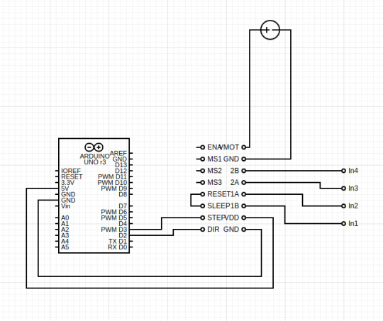
On the left we have the Arduino uno, in the middle we have our stepper motor driver, on the right our stepper motor inputs and on the top our 12V DC power supply.
This allowed us to be able to control the stepper motor like you can see in this video:
vimeo
We then did a few more experiments and tried adding a potentiometer to the circuit so that we would be able to control how fast it spins
#define dirPin 2
#define stepPin 3
#define stepsPerRevolution 200
void setup(){
pinMode(stepPin, OUTPUT);
pinMode(dirPin, OUTPUT);
}
void loop(){
digitalWrite(dirPin,low);
int sensorValue = analogRead(A0);
sensorValue = map(sensorValue, 0, 1023, 350, 2500);
for(int i = 0; i < stepsPerRevolution; i++){
digitalWrite(stepPin, HIGH);
delayMicroseconds(sensorValue);
digitalWrite(stepPin, LOW);
delayMicroseconds(sensorValue);
}
delay(100);
digitalWrite(dirPin, HIGH);
for(int i = 0; i < stepsPerRevolution; i++){
digitalWrite(stepPin, HIGH);
delayMicroseconds(sensorValue);
digitalWrite(stepPin, LOW);
delayMicroseconds(sensorValue);
}
delay(100);
}
Turn your sound on because the following video is a very interesting experiment we were able to achieve by using the vibrations of the stepper motor as an instrument.
vimeo
We finally finished this experiments by attaching a laser to the stepper motor and here is the result.
vimeo
0 notes
Text
Drones

This infographic is focused on getting the users to use/buy drones. Drones are quickly becoming more and more popular and are starting to be used by anyone across any age range.
I’ve focused on showing the users that they are not old/young enough to use a drone as seen by the statistics on the charts. I’ve also proven that the drone’s market is on the rise which means it would be easier for people to get started with drones and getting to know other people who own drones as well. I’ve built a word-cloud with interesting keywords to convince users to join this unique experience.


All in all, I think it’s clear to the point but it’s not exactly a pretty display of information.
References:
https://www.dronesdirect.co.uk/files/pdf/dronesreport.pdf
https://www.makeuseof.com/tag/crazy-drone-activities/
https://www.faa.gov/data_research/aviation/aerospace_forecasts/media/Unmanned_Aircraft_Systems.pdf
0 notes
Text
Week 3
This week we learnt about servo motors, what they are and what can we use them for. A servo motor is an electrical device which can push or rotate an object with great precision.
This week’s project I’m gonna be building a “robot” that faces whatever side of it has more light (brightness). For this project we going to need a servo motor, a LDR (photoresistor to detect light) and a resistor which will be incorporated in the LDR circuit. Here’s the schematic for it:
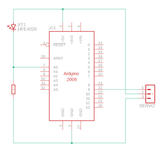
So now we jump into the coding part. The logic here is that the servo has to rotate every couple of milliseconds in both directions to try and find which direction points towards the strongest light. The way we going to be getting the light readings is by using the LDR which will be attached to the servo as it rotates.
#include <Servo.h>
Servo servo; // create servo object to control a servo
int lightPin = A0; // analog pin used to connect the potentiometer int lightValue = 0; int lightValue2 = 0; int pos = 90;
void setup() { Serial.begin(9600); pinMode(lightPin, INPUT); servo.attach(9); // attaches the servo on pin 9 to the servo object }
So we start by including the servo library which allows us to control the servo motor. We initialize the library by creating a variable for it using “Servo servo” and finally we can initialize all the variables we need. In this case we gonna be using A0 for the LDR and we need two variables to store the light values of each side that the servo rotates too. We also need a variable that indicates what the position of the servo is which I set as default to 90 degrees.
On the setup bit we initialize the Serial so that we can debug the program easier and we set the LDR pin to be an INPUT because we want to be reading the values from it. We then define that the servo is attached to pin number 9 on our arduino using “servo.attach”.
void loop() { servo.write(pos);
delay(15);
int value = analogRead(lightPin);
Serial.println(“*——————————–*”);
Serial.println(value);
int positive1 = 0; int positive2 = 0;
if((pos+5) < 180) { Serial.println(“Go up and read”); servo.write(pos+5); delay(200); positive1 = analogRead(lightPin); if((pos+10) < 180) { servo.write(pos+10); delay(200); positive2 = analogRead(lightPin);
if(positive2 > positive1) { pos += 10; } } }
We start the loop by telling the servo to move into the current position (in the start it will be the 90 degrees). After that we read the light value and we print it just to make sure it’s working and that we have some feedback coming into the console.
We then start by moving the servo “up” which means that the degrees are gonna increase by 5 and we take a reading, we then move it up again by 5 more degrees and take another reading. If the second reading is higher than the first it means it’s turning into the direction of a stronger point of light if not it will just go back to the default position it was before.
int negative1 = 0; int negative2 = 0;
if((pos-5) < 180) { Serial.println(“Go down and read”); servo.write(pos-5); delay(200); negative1 = analogRead(lightPin); if((pos-10) < 180) { servo.write(pos-10); delay(200); negative2 = analogRead(lightPin);
if(negative2 > negative1) { pos -= 10; } } } Serial.println(“”); }
We then do the exact same thing but to the other side (going down). This way we have a functional mini robot that can follow light. It’s a very fun project to create and it shows how much you can do with so little components using Arduino! Here’s the video below showing the results where we can see the “mini robot” following the phones flash light while recording:
vimeo
0 notes
Text
Week 2
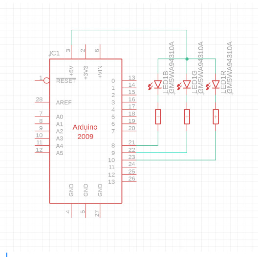
This week I’ve decided to play around with an RGB LED. The requirements for this project are a cathode/anode (cathode as the bigger “leg” as the GND opposite to anode which has the bigger “leg” as the positive) RGB LED and 3 resistors too. Here’s the schematic:
Now when it comes to the coding I’ve tried to do multiple different things but I’ll go through them one by one. I first set my led variables.
int redPin= 9; int greenPin = 10; int bluePin = 11;
Secondly I’ve set my variables for the values of each colour (defaulting at 0).
int red = 0; int green = 0; int blue = 0;
And then the triggers and counters (will get to that later)
int redTrigger = false; int greenTrigger = false; int blueTrigger = false; int redCounter = 1; int greenCounter = 5; int blueCounter = 10;
On the setup I’ve initialized my console and I set the pins as outputs.
void setup() { Serial.begin(9600); pinMode(redPin, OUTPUT); pinMode(greenPin, OUTPUT); pinMode(bluePin, OUTPUT); }
I then built a function named RGB_color which takes 3 parameters, the red, green and blue values. This function is used to tell the micro-controller which voltage it needs to give to each LED. The reason why a map function is being used is because this RGB LED is an anode which means that if you give it a value of 1 (or 255 since we are using PWM) it will turn that LED off while usually an 1 would turn it on.
void RGB_color(int red, int green, int blue) { red = map(red, 0, 255, 255, 0); green = map(green, 0, 255, 255, 0); blue = map(blue, 0, 255, 255, 0); analogWrite(redPin, red); analogWrite(greenPin, green); analogWrite(bluePin, blue); }
I then created two more functions named fadeIn and fadeOut and they take as parameters the colour (1-red, 2-green, 3-blue) and the time for the fade.
void fadeIn(int colour, int delayTime) { for(int i = 0; i < 255; i++) { switch(colour) { case 1: RGB_color(i, 0, 0); break; case 2: RGB_color(0, i, 0); break; case 3: RGB_color(0, 0, i); break; } delay(delayTime); } }
void fadeOut(int colour, int delayTime) { for(int i = 255; i > 0; i--) { switch(colour) { case 1: RGB_color(i, 0, 0); break; case 2: RGB_color(0, i, 0); break; case 3: RGB_color(0, 0, i); break; } delay(delayTime); } }
With this setup, by simply calling “fadeIn(1, 100);” inside the void loop function we could see the led increment 1 value every 100 milliseconds until it reaches the maximum value of 255 which then it would repeat again the fade effect.
After this effects were in place I also experimented with random colour! The way I did this was by simply randomizing the values of R, G and B. By using a built in function of Arduino named random(), we can get random values within the amount we input on the parameter. Here’s the code I used to randomize my colours.
red = random(255); green = random(255); blue = random(255); RGB_color(red, green, blue); delay(200);
vimeo
And this is all for this week. See you next week!
0 notes
Text
Week 1
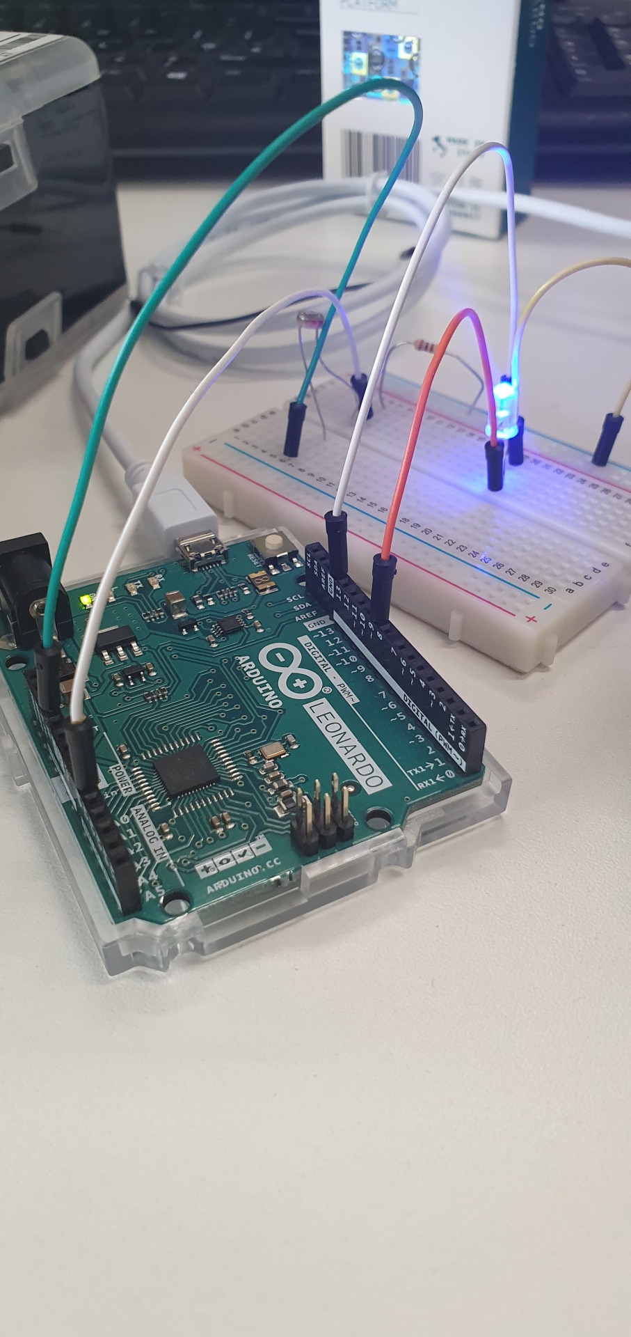
This week we started to learn the basics of using an Arduino. Arduino is a open-source hardware and software company which produces micro-controllers such as Arduino Leonardo which is the one we are using.
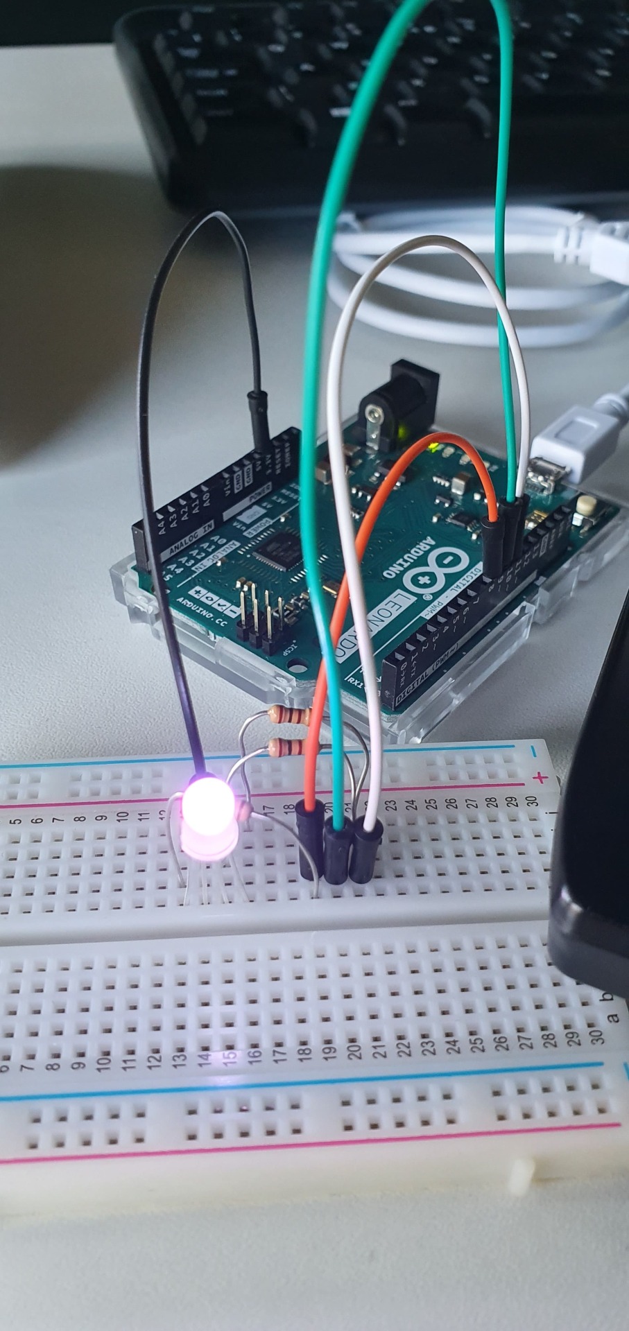
Arduino has an IDE which is what I’m gonna be using to code the micro-controller. On this week I’ve decided to create a project where a LED gets stronger the less light there is in the room. In order to create this project I had to use an Arduino Leonardo, a LDR (Photoresistor, or in other words a light sensor), an LED and a resistor.
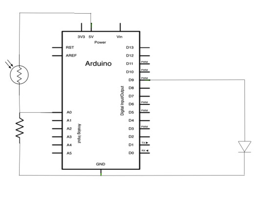
The LDR is powered by 5V and then read on the port A0 which is an analog pin (takes values between 0-1023) opposed to the digital pins (either 0 or 1 unless it’s a PWN pin). It is also connected to the GND via a resistor. On the other side we have an LED connected to the digital port D9 and then also connected to the GND. Now, in order to make this work the way we want to, we gonna have to code it. On any Arduino IDE script we are required to have two functions, setup and loop. Setup function is ran once and that’s usually where we define the pin input/outputs and other variables too. The loop function however is as the name suggests, a function that loops continuously after each iteration.
int analog = A0; int led = 9; int value = 0;
As we can see, there are 3 variables named analog, led and value. Analog has the pin position of our LDR sensor, led has the pin position of the LED and value carries the value read by the LDR (defaulting to 0 in the beginning of the code).
void setup() { Serial.begin(9600); pinMode(analog, INPUT); pinMode(led, OUTPUT); }
On the setup class we initialize the Serial so that we can have some output in the console, 9600 is the default baudrate. After we have the pinMode function that defines the pins as either inputs or outputs.
void loop() { value = analogRead(analog); value = map(value, 5, 200, 0, 255); Serial.println(value); analogWrite(led, value); }
Finally we have our loop function that runs the main code. We first take the value read by the LDR by using analogRead and we store it in the variable named value. Secondly, we transform the values from the LDR (in my case the values were floating between the 5 and the 200) and we turn them from 0 to 255. The reason why is because pin D9 is a PWM pin which means it can transmit 0-255 where 0 is 0 and 255 is 1, this gives us the flexibility to decrease or increase the LEDs brightness.
We then print into the console the value that we got and lastly we tell the micro-controller to send that value into the LED pin by using analogWrite.
Here’s the end result:
vimeo
If we reverse the led to go from 0-255 to 255-0 we have ourselves an automatic light sensor system that can turn the lights on in your house as the sun sets and automatically dim them as the sun rises.
See you next week!
0 notes